Impact Loading, Suddenly Applied Loads & Dynamic Factor
In this chapter (3 topics)
On this page
- Metadata
- 1. Engineering Fundamentals & Theoretical Basis
- Fundamental Conservation of Energy
- 2. Mathematical Derivations & Complete Proofs
- 2.1 Derivation 1: Suddenly Applied Load (h = 0) and the Factor of 2.0
- 2.2 Derivation 2: Impact from Falling Weight (h > 0) & Dynamic Load Factor (DLF)
- 2.3 Derivation 3: The "Impact Paradox" in Axial Bars
- 2.4 Derivation 4: Horizontal Impact & Velocity Impact (v)
- 2.5 Derivation 5: Inertia of Struck Member & Cox's Correction Factor
- 3. Engineering Visualizations & Technical Diagrams
- Diagram 1: Impact Loading Mechanics & Energy Balance
- Diagram 2: Dynamic Load Factor Curves & The Impact Design Paradox
- 4. Comprehensive Comparison Tables
- Table 1: Loading Regimes Comparative Matrix
- Table 2: Static Deflections & Stiffness for Standard Impact Elements
- Table 3: Normalized Drop Height (h/δst) vs. Dynamic Load Factor (DLF)
- 5. Fully Solved Numerical Examples
- Example 1: Vertical Hanging Steel Tie Rod Subjected to Falling Collar Load
- Example 2: Impact of Falling Mass on Simply Supported I-Beam
- Example 3: Horizontal Impact on End Buffer Spring & Kinetic Energy Absorption
- 6. Common Misconceptions & High-Yield Exam Traps
- Misconception 1: "The Dynamic Load Factor for sudden loading is 1.0 because height h = 0"
- Misconception 2: "Stiffer structures are safer against impact loading"
- Misconception 3: "Doubling the cross-sectional area halves impact stress"
- Misconception 4: "Neglecting δdyn inside W(h + δdyn) is always acceptable"
- Misconception 5: "Static yield stress governs impact failure"
- 7. Previous Years Questions & Benchmark Solutions
- Question 1 (GATE CE)
- Question 2 (UPSC ESE)
- Question 3 (SSC JE / State AE)
- 8. Indian Standard (IS) Code References & Design Implications
- 9. Quick Revision Formulas & Key Exam Takeaways
Metadata
- Topic ID:
SOM-10-03 - Module: Subject 02: Strength of Materials
- Chapter: Chapter 10: Strain Energy & Impact Loading
- Author: Civil Engineering Autonomous Content & QA Agent
- Standard Reference: IS 800:2007, IS 456:2000, IS 1893:2016, IRC:6-2017
- Target Examinations: GATE CE, UPSC ESE, SSC JE, State AE/JE, RRB JE
1. Engineering Fundamentals & Theoretical Basis
In structural design, external loads are classified based on the rate and nature of application relative to the fundamental natural period of vibration of the structure ():
-
Gradually Applied Loading (Static):
- The load increases slowly from zero to its maximum value over a duration .
- At every intermediate stage, internal elastic resistance equals external applied force.
- Kinetic energy is zero, and inertia forces are negligible.
- Work done by external force:
- Internal strain energy stored:
-
Suddenly Applied Loading ():
- The full magnitude of load is placed instantaneously onto the structure without initial velocity or drop height ().
- As the structure deforms from to dynamic displacement , the full load remains constant throughout displacement.
- Kinetic energy accelerates the structure past the static equilibrium point until all work is converted into peak elastic strain energy at maximum deflection.
-
Impact Loading (Falling Weight from Height ):
- A weight falls freely from height above the contact point, striking the structure with initial contact velocity .
- The total potential energy lost by the falling mass is completely absorbed by the structure as internal elastic strain energy at peak instantaneous deflection.
Fundamental Conservation of Energy
Assuming:
- Perfectly elastic deformation obeying Hooke's Law up to peak deflection.
- No thermal dissipation or plastic deformation at contact surfaces.
- The mass of the structural member is negligible compared to the impacting mass ().
The Energy Balance Equation at the instant of maximum deflection (, instantaneous rest) is:
2. Mathematical Derivations & Complete Proofs
2.1 Derivation 1: Suddenly Applied Load () and the Factor of 2.0
Consider a weight placed suddenly onto an unstrained elastic structure of stiffness .
     W (at rest, zero drop)
     ↓
  ════════════ (Unstrained: δ = 0)
     :
     : (Deformation under full constant force W)
     ↓
  ════════════ (Peak Deflection: δ = δ_dyn)
-
External Work Done: Since the full weight acts constantly throughout the entire dynamic displacement :
-
Internal Strain Energy Stored: Since internal resistance increases linearly with displacement ():
-
Equating Work and Energy:
Dividing by :
Recall that the static deflection produced by gradual application of is:
Therefore:
Since stress is directly proportional to displacement within the elastic limit ():
Universal Engineering Law: The maximum instantaneous deformation and dynamic stress induced by a suddenly applied load are exactly twice the values caused by the same load applied gradually ().
2.2 Derivation 2: Impact from Falling Weight () & Dynamic Load Factor (DLF)
Let a weight drop through height onto a structure of static stiffness :
Expand and rearrange into standard quadratic form:
Multiply the entire equation by :
Substitute the static deflection :
Solving this quadratic equation for physical positive displacement :
Factoring out and discarding the unphysical negative root:
Definition of Dynamic Load Factor (DLF) / Impact Factor ():
Maximum dynamic stress:
Asymptotic Regimes:
- Zero Drop Height ():
- Large Drop Height ():
- Extremely Rigid Member (): An infinitely rigid member cannot store strain energy without infinite stress. Flexibility is mandatory to survive impact!
2.3 Derivation 3: The "Impact Paradox" in Axial Bars
Consider a hanging prismatic bar of length , cross-sectional area , and elastic modulus subjected to falling weight dropped from height .
- Static stress:
- Static deflection:
Substitute into the dynamic stress formula:
When :
where is the total volume of the bar.
The Three Impact Design Paradoxes:
- Length Paradox: In static design, bar length has zero effect on stress (). Under impact loading, increasing length lowers dynamic stress ()! A longer bar is more flexible (), dissipating the kinetic energy over a longer stroke.
- Area Paradox: In static design, doubling area halves stress. In impact design with large , stress is inversely proportional only to the square root of volume ().
- Modulus Paradox: In static design, higher reduces deflection without changing stress. Under impact loading, higher increases dynamic stress ()! A stiffer material experiences higher shock stresses.
2.4 Derivation 4: Horizontal Impact & Velocity Impact ()
When a body of mass (weight ) moves horizontally with velocity and collides with an elastic structure of stiffness :
- Initial Kinetic Energy:
- Peak Elastic Strain Energy:
- Energy Balance:
Expressing in terms of static deflection :
Dynamic Load Factor for velocity impact:
Dynamic stress:
where is the material density. This shows that the impact stress in a one-dimensional bar under direct velocity impact is a function only of velocity and material wave acoustic impedance .
2.5 Derivation 5: Inertia of Struck Member & Cox's Correction Factor
In reality, the struck structural member possesses mass , part of which must be accelerated instantaneously upon impact, causing an inelastic kinetic energy loss:
For a simply supported beam struck at midspan by mass (Cox's formula):
When the beam mass is significant (), nearly of the initial impact energy is dissipated into local plastic indentation and shock wave dispersion. Assuming zero beam mass () is always conservative for structural safety.
3. Engineering Visualizations & Technical Diagrams
Diagram 1: Impact Loading Mechanics & Energy Balance
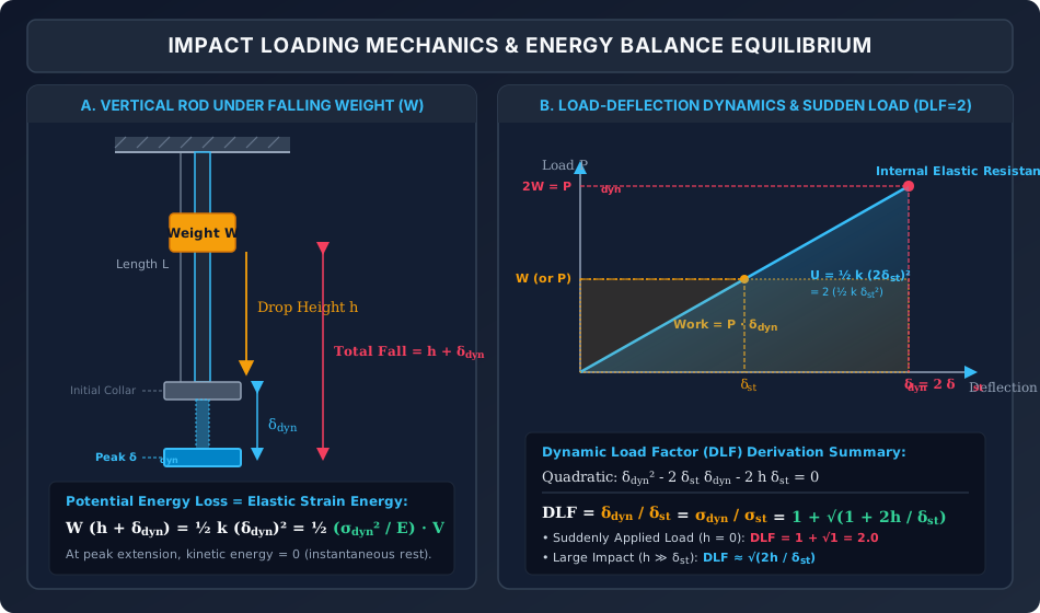
The figure below illustrates the physical mechanics of a falling weight striking an axial rod, along with the load-deflection proof for suddenly applied loads.
Analytical Walk-Through:
- Vertical Rod Mechanics (Panel A): Shows the falling weight dropping through clearance and further through dynamic elongation . Total potential energy drop is .
- Load-Deflection Energy Balance (Panel B): Demonstrates that a suddenly applied load () applies constant force through distance , forming a rectangular work area . Equating this to the elastic resisting triangle proves that and .
Diagram 2: Dynamic Load Factor Curves & The Impact Design Paradox
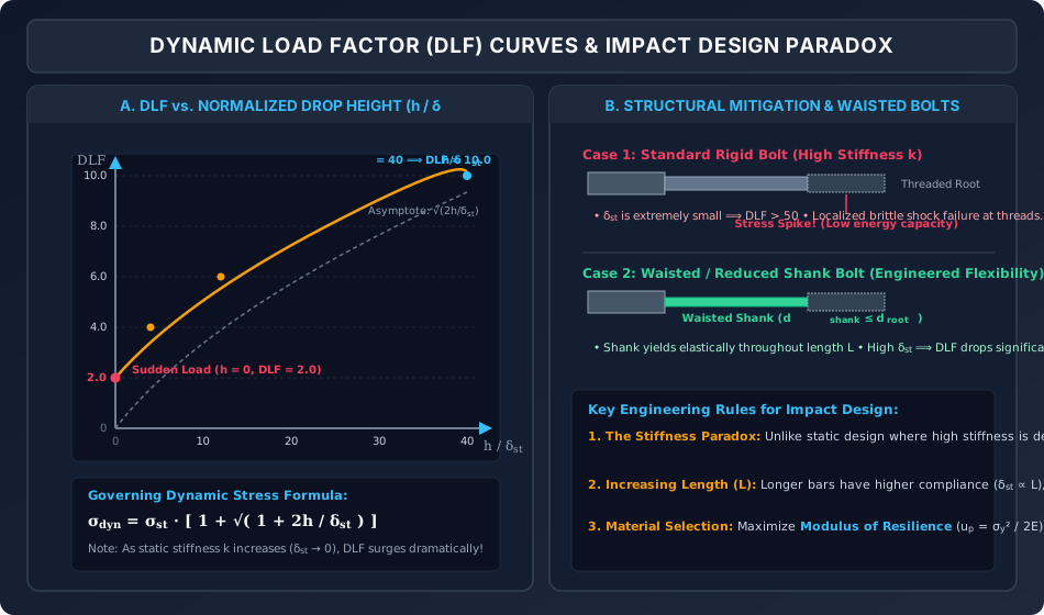
The graphic below charts the non-linear growth of the Dynamic Load Factor as a function of drop height and illustrates structural impact mitigation using waisted bolts.
Analytical Walk-Through:
- DLF Curve (Panel A): Begins at for and scales non-linearly with . For small static deflections (stiff structures), DLF rapidly exceeds to .
- Impact Mitigation & Waisted Bolts (Panel B): A standard stiff bolt concentrates stress at threaded roots, causing brittle shock failure. A waisted bolt with reduced shank diameter yields elastic flexibility along its entire shank, increasing and multiplying energy absorption capacity by .
4. Comprehensive Comparison Tables
Table 1: Loading Regimes Comparative Matrix
| Feature | Gradual (Static) Loading | Suddenly Applied Loading () | Impact Loading () |
|---|---|---|---|
| Duration of Application () | (very slow) | (instantaneous, zero drop) | Shock contact () |
| External Work Expression | |||
| Dynamic Load Factor (DLF) | |||
| Max Dynamic Stress () | |||
| Max Dynamic Deflection () | |||
| Oscillation after Application | None (Static rest) | Harmonic oscillation about | Transient damped oscillation |
Table 2: Static Deflections & Stiffness for Standard Impact Elements
| Structural Element | Static Deflection Under Weight () | Static Bending / Axial Stress () | Equivalent Stiffness () |
|---|---|---|---|
| Axial Hanging Rod | |||
| Cantilever Beam (Tip Drop) | |||
| Simply Supported Beam (Midspan) | |||
| Fixed-Fixed Beam (Midspan) |
Table 3: Normalized Drop Height () vs. Dynamic Load Factor (DLF)
| Exact DLF: | Asymptotic Approx: | Practical Meaning | |
|---|---|---|---|
| Suddenly applied load (zero drop) | |||
| Drop height equal to static deflection | |||
| Moderate impact | |||
| Heavy industrial drop | |||
| Severe crane shock | |||
| High-velocity forging / pile hammer | |||
| Asymptote within error |
5. Fully Solved Numerical Examples
Example 1: Vertical Hanging Steel Tie Rod Subjected to Falling Collar Load
Problem Statement:
A vertical structural steel tie rod of length and circular diameter is fixed rigidly at its top end. A collar is rigidly attached to the bottom end of the rod. A weight drops freely through height onto the collar before striking it.
Given: Elastic modulus .
Calculate:
- The static stress and static deflection of the rod under weight .
- The Dynamic Load Factor (DLF).
- The maximum dynamic stress and maximum dynamic elongation .
- Compare with the values if the load were applied suddenly with zero drop height ().
Step 1: Geometric & Static Properties
Cross-sectional area:
Static stress:
Static elongation:
Step 2: Compute the Dynamic Load Factor (DLF)
Normalized drop height:
Dynamic Load Factor:
Step 3: Maximum Dynamic Responses
Maximum dynamic elongation:
Maximum dynamic tensile stress:
Step 4: Comparison with Suddenly Applied Load ()
For :
Exam Observation: The dynamic stress from dropping the load merely () is times greater than the suddenly applied stress (), and times greater than the static stress ()!
Example 2: Impact of Falling Mass on Simply Supported I-Beam
Problem Statement:
A rolled steel I-beam ISMB 200 is simply supported over a span . A mass is dropped from a height onto the midpoint of the beam.
Beam section properties: , elastic section modulus , total depth ().
Given: , .
Calculate:
- Static deflection and static bending stress at midspan.
- The Dynamic Load Factor (DLF).
- Maximum dynamic midspan deflection and maximum dynamic bending stress.
Step 1: Weight and Static Quantities
Impact weight:
Static midspan deflection:
Static bending moment at center:
Static bending stress:
Step 2: Compute DLF
Step 3: Maximum Dynamic Responses
Maximum dynamic center deflection:
Maximum dynamic bending stress:
Check against structural steel yield stress ():
Example 3: Horizontal Impact on End Buffer Spring & Kinetic Energy Absorption
Problem Statement:
A maintenance rail trolley of mass travels horizontally at speed () and collides with an elastic bumper spring system at the track terminal. The bumper spring has a linear stiffness .
Calculate:
- The total kinetic energy absorbed by the buffer spring.
- The maximum dynamic compression of the spring.
- The peak dynamic impact force exerted on the terminal buffer stop.
- The maximum deceleration experienced by the trolley during impact.
Step 1: Kinetic Energy Calculation
Step 2: Maximum Spring Compression
At maximum compression, all kinetic energy is stored as elastic strain energy:
Step 3: Peak Dynamic Impact Force
Step 4: Maximum Deceleration
In terms of acceleration due to gravity :
6. Common Misconceptions & High-Yield Exam Traps
Misconception 1: "The Dynamic Load Factor for sudden loading is because height "
- The Trap: Thinking that because there is no drop height (), the load is static ().
- Correction: When a load is suddenly applied, it acts with full magnitude from the very first instant without gradual ramping. The work done is (a full rectangle), whereas internal resistance starts at zero. Equating rectangular work to the triangular strain energy yields .
Misconception 2: "Stiffer structures are safer against impact loading"
- The Trap: Designing an impact-resistant member by making it thicker, shorter, or more rigid ().
- Correction: Under static loading, stiffness reduces deflection. Under impact loading, kinetic energy is fixed ( or ). Stiffer structures have smaller static deflection (), which causes the dynamic load factor and dynamic stress to surge: Impact resistance requires high compliance (resilience) and larger volume to absorb energy without stress peaks!
Misconception 3: "Doubling the cross-sectional area halves impact stress"
- The Trap: Assuming just like static stress .
- Correction: When drop height , dynamic stress is: Doubling the area reduces dynamic stress by only a factor of ( reduction), not by half ().
Misconception 4: "Neglecting inside is always acceptable"
- The Trap: Approximating work as when is comparable to .
- Correction: If , omitting yields , which is absurd! The term represents the additional potential energy lost as the weight displaces the member. It can only be neglected when .
Misconception 5: "Static yield stress governs impact failure"
- The Trap: Assuming structural steel yields at under rapid shock impact.
- Correction: High strain rates () increase the apparent yield strength of structural steel by (strain rate hardening), but severely degrade ductility, inducing brittle cleavage fracture. Impact design must prioritize Charpy V-notch toughness (IS 1757) rather than static yield strength alone.
7. Previous Years Questions & Benchmark Solutions
Question 1 (GATE CE)
Problem: A weight is dropped from a height onto the free end of a cantilever beam of length and flexural rigidity . If the drop height is very large compared to the static deflection , the maximum dynamic deflection at the free end is proportional to:
(A)
(B)
(C)
(D)
Solution:
- Static deflection of cantilever under tip load :
- For :
- Substitute : Therefore:
Correct Answer: (C) .
Question 2 (UPSC ESE)
Problem: A load is applied suddenly on a vertical bar of length and cross-sectional area . The maximum strain energy stored in the bar during dynamic motion is:
(A)
(B)
(C)
(D)
Solution:
- Under a suddenly applied load :
- The strain energy stored at peak displacement:
Correct Answer: (C) .
(Note: This is exactly 4 times the static strain energy !)
Question 3 (SSC JE / State AE)
Problem: The ratio of maximum dynamic stress to static stress produced by a suddenly applied axial load is:
(A)
(B)
(C)
(D)
Solution: For suddenly applied loads ():
Correct Answer: (C) 2.0.
8. Indian Standard (IS) Code References & Design Implications
- IS 800:2007 — Clause 3.4 & Clause 5.6 (Impact Allowance in Cranes):
- For overhead travelling crane gantries, electric cranes introduce dynamic impact on bridge girders and runway girders.
- Standard impact allowances specified by IS 800:
- Vertical impact factor for EOT cranes: of maximum static wheel load.
- Vertical impact factor for hand-operated cranes: .
- Transverse horizontal surge load: of trolley weight plus lifted load.
- Longitudinal horizontal tractive force: of static wheel loads.
- IS 456:2000 — Clause 34.4 (Impact on Foundations):
- Foundations supporting drop hammers, forging presses, and reciprocating machinery must be designed for dynamic impact factors typically ranging from to times machine weight to prevent soil resonance and foundation cracking.
- IRC:6-2017 — Clause 208 (Impact Factor for Highway Bridges):
- Live load vehicles travelling across highway bridges generate dynamic amplification due to deck roughness and vehicle bouncing.
- For reinforced concrete and steel bridges under IRC Class A or Class B loading, the impact percentage is given by: where is the span length in meters.
9. Quick Revision Formulas & Key Exam Takeaways
╔═══════════════════════════════════════════════════════════════════════════════╗
║                      IMPACT LOADING FORMULA CHEAT SHEET                       ║
╠═══════════════════════════════════════════════════════════════════════════════╣
║ 1. Dynamic Load Factor (DLF):                                                 ║
║    DLF = 1 + √( 1 + 2h / δst )                                                ║
║    • Suddenly applied load (h = 0):   DLF = 2.0                               ║
║    • Large drop height (h ≫ δst):     DLF ≈ √( 2h / δst )                     ║
║                                                                               ║
║ 2. Maximum Dynamic Responses:                                                 ║
║    • Deflection:  δdyn = δst · DLF = δst [ 1 + √( 1 + 2h / δst ) ]            ║
║    • Stress:      σdyn = σst · DLF = σst [ 1 + √( 1 + 2h / δst ) ]            ║
║    • Peak Force:  Pdyn = W · DLF                                              ║
║                                                                               ║
║ 3. Strain Energy at Peak Dynamic Deflection:                                  ║
║    • Static:          Ust = ½ k δst² = P² L / (2AE)                           ║
║    • Suddenly applied: Udyn = ½ k (2δst)² = 4 Ust = 2 P² L / (AE)             ║
║                                                                               ║
║ 4. Horizontal / Velocity Impact (Mass m, velocity v):                         ║
║    • Deflection:  δdyn = v √(m / k) = v √(δst / g)                            ║
║    • DLF:         DLF = v / √(g · δst)                                        ║
║                                                                               ║
║ 5. The Impact Design Paradoxes:                                               ║
║    • σdyn ∝ 1 / √L     (Longer bars have LOWER impact stress!)                ║
║    • σdyn ∝ √E         (Stiffer materials experience HIGHER impact stress!)   ║
║    • σdyn ∝ 1 / √V     (Energy capacity depends on total volume V = A·L)      ║
║                                                                               ║
║ 6. Engineering Mitigations:                                                   ║
║    • Use Waisted Bolts (turn down shank to thread root diameter dshank ≤ droot)║
║    • Maximize Proof Resilience (high yield strength σy with lower E)          ║
║    • Provide elastomeric shock buffer pads / spring dampeners                 ║
╚═══════════════════════════════════════════════════════════════════════════════╝