SOM-09-03 Chapter 09 · Thin and Thick Cylinders

Thick Cylinders, Lamé's Equations & Compound Cylinders

In this chapter (3 topics)
On this page

1. Topic Title & Metadata Header

  • Topic ID: SOM-09-03
  • Module / Subject: Strength of Materials (Mechanics of Solids)
  • Chapter 09: Thin and Thick Cylinders & Spherical Shells
  • Topic Title: Thick Cylinders, Lamé's Differential Theory, and Compound Shrink-Fit Cylinders
  • Prerequisites: SOM-01-03 (Generalized Hooke's Law), SOM-02-01 to SOM-02-03 (Biaxial Stress & Mohr's Circle), SOM-09-01 & SOM-09-02 (Thin Cylinder Fundamentals).
  • Target Examinations: GATE CE, UPSC ESE (Civil), SSC JE (Civil), State AE/JE, RRB JE (Civil).
  • Quality Assurance Gate: Level 1 through Level 7 Verification Protocol Enforced.

2. Introduction & Physical Engineering Significance

When the wall thickness tt of a cylinder exceeds one-twentieth of its internal diameter (t/d>1/20t / d > 1/20 or t/ri>0.10t / r_i > 0.10), the fundamental assumptions of thin-shell theory break down:

  1. The circumferential (hoop) stress σh\sigma_h is not uniformly distributed across the wall thickness; it varies non-linearly (hyperbolically), concentrating heavily at the inner bore and decaying towards the outer surface.
  2. The radial stress σr\sigma_r is not negligible; it is of the same order of magnitude as the internal pressure pip_i and must be accounted for in the 3-dimensional stress tensor.
  3. Every point within the cylinder wall is in a full triaxial state of stress governed by principal stresses σh\sigma_h (tensile hoop), σr\sigma_r (compressive radial), and σL\sigma_L (longitudinal axial).

Thick cylinder theory is essential in heavy civil and mechanical engineering systems:

  • Ultra-high-pressure hydraulic cylinders and jacking rams used in bridge prestressing,
  • High-pressure water conduits, deep mining shafts, and penstocks penetrating massive rock masses,
  • Subsea oil, gas, and slurry pipelines subjected simultaneously to high internal pressure and crushing external hydrostatic seabed pressure,
  • Extrusion press containers, cannon barrels, and nuclear reactor pressure vessels.

3. Foundational Assumptions & Governing Conditions

Gabriel Lamé developed the classical theory of thick-walled cylinders based on the following engineering assumptions:

  1. Geometry Criterion: The wall thickness tt is substantial relative to the internal radius rir_i: tdi>120(or tri>0.10)\frac{t}{d_i} > \frac{1}{20} \quad \left(\text{or } \frac{t}{r_i} > 0.10\right)
  2. Homogeneous & Isotropic Material: The material is linearly elastic, obeying Hooke's Law (EE and ν\nu are constant).
  3. Axisymmetry: Geometry, loading, and boundary conditions are completely symmetric about the longitudinal axis of revolution. Shear stresses on radial and circumferential planes are zero (τrθ=0\tau_{r\theta} = 0).
  4. Plane Sections Remain Plane: Transverse cross-sections perpendicular to the longitudinal axis remain plane and parallel after deformation. Consequently, the longitudinal strain ϵL\epsilon_L is constant across the entire cross-section: ϵL=constant\epsilon_L = \text{constant}

4. Mathematical Derivation of Lamé's Differential Equations

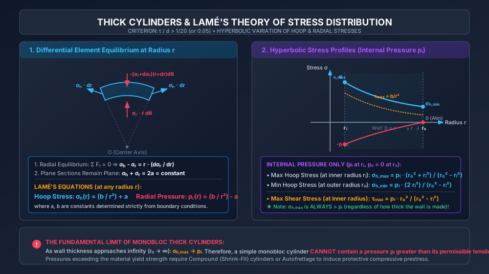
Consider an elemental ring sector of the cylinder wall at radius rr, thickness drdr, subtending a small angle dθd\theta, with unit axial length (L=1L = 1).

4.1 Radial Equilibrium Equation

Let:

  • σr=\sigma_r = radial stress acting on the inner face at radius rr (tensile taken positive, though physically compressive),
  • σr+dσr=\sigma_r + d\sigma_r = radial stress acting on the outer face at radius r+drr + dr,
  • σh=\sigma_h = circumferential (hoop) stress acting on the radial side faces.

The forces acting on the elemental block are:

  1. Outward radial force on inner face: Fr,inner=σr⋅(r dθ⋅1)F_{r,\text{inner}} = \sigma_r \cdot (r \, d\theta \cdot 1)
  2. Inward radial force on outer face: Fr,outer=(σr+dσr)⋅[(r+dr) dθ⋅1]F_{r,\text{outer}} = (\sigma_r + d\sigma_r) \cdot [(r + dr) \, d\theta \cdot 1]
  3. Tangential forces on two lateral side faces: Fh=2⋅(σh⋅dr⋅1)F_h = 2 \cdot (\sigma_h \cdot dr \cdot 1) Because the lateral faces are inclined at angle dθ2\frac{d\theta}{2} to the radial centerline, their components resolved radially inward are: 2⋅Fhsin⁡(dθ2)≈2⋅(σh⋅dr)(dθ2)=σh⋅dr⋅dθ2 \cdot F_h \sin\left(\frac{d\theta}{2}\right) \approx 2 \cdot (\sigma_h \cdot dr) \left(\frac{d\theta}{2}\right) = \sigma_h \cdot dr \cdot d\theta

Equating forces in the radial direction (ΣFr=0\Sigma F_r = 0):

(σr+dσr)(r+dr)dθ−σr⋅r dθ−σh⋅dr⋅dθ=0(\sigma_r + d\sigma_r)(r + dr) d\theta - \sigma_r \cdot r \, d\theta - \sigma_h \cdot dr \cdot d\theta = 0

Expanding and dividing through by dθd\theta:

σrr+σrdr+rdσr+dσrdr−σrr−σhdr=0\sigma_r r + \sigma_r dr + r d\sigma_r + d\sigma_r dr - \sigma_r r - \sigma_h dr = 0 σrdr+rdσr−σhdr+dσrdr=0\sigma_r dr + r d\sigma_r - \sigma_h dr + d\sigma_r dr = 0

Neglecting the second-order differential product dσrdrd\sigma_r dr:

(σr−σh)dr+rdσr=0(\sigma_r - \sigma_h) dr + r d\sigma_r = 0 σh−σr=rdσrdr— (Equation 1: Equilibrium)\sigma_h - \sigma_r = r \frac{d\sigma_r}{dr} \quad \text{--- (Equation 1: Equilibrium)}

4.2 Kinematic Compatibility Condition

Applying Generalized Hooke's Law for the longitudinal strain ϵL\epsilon_L:

ϵL=σLE−νσhE−νσrE=1E[σL−ν(σh+σr)]\epsilon_L = \frac{\sigma_L}{E} - \nu \frac{\sigma_h}{E} - \nu \frac{\sigma_r}{E} = \frac{1}{E} [ \sigma_L - \nu (\sigma_h + \sigma_r) ]

Since plane sections remain plane, ϵL\epsilon_L is constant. Furthermore, for open-ended cylinders σL=0\sigma_L = 0, and for closed-ended cylinders σL\sigma_L is uniform across the cross-section. Therefore:

σh+σr=constant=2a— (Equation 2: Compatibility)\sigma_h + \sigma_r = \text{constant} = 2a \quad \text{--- (Equation 2: Compatibility)}

where aa is an integration constant.


4.3 Integration to Obtain Lamé's Equations

From Equation 2:

σh=2a−σr\sigma_h = 2a - \sigma_r

Substitute this into Equilibrium Equation 1:

(2a−σr)−σr=rdσrdr  ⟹  2a−2σr=rdσrdr(2a - \sigma_r) - \sigma_r = r \frac{d\sigma_r}{dr} \implies 2a - 2\sigma_r = r \frac{d\sigma_r}{dr} 2a=2σr+rdσrdr2a = 2\sigma_r + r \frac{d\sigma_r}{dr}

Multiply both sides by rr:

2ar=2rσr+r2dσrdr=ddr(r2σr)2a r = 2r \sigma_r + r^2 \frac{d\sigma_r}{dr} = \frac{d}{dr} (r^2 \sigma_r)

Integrating both sides with respect to rr:

∫ddr(r2σr) dr=∫2ar dr\int \frac{d}{dr} (r^2 \sigma_r) \, dr = \int 2a r \, dr r2σr=ar2−br^2 \sigma_r = a r^2 - b

where −b-b is a second constant of integration.

Dividing by r2r^2:

σr=a−br2\sigma_r = a - \frac{b}{r^2}

In engineering mechanics, radial stress is compressive (σr=−pr\sigma_r = -p_r, where prp_r is internal radial compressive fluid pressure). Taking pr=−σrp_r = -\sigma_r:

pr=br2−a  ⟹  σr=a−br2(Radial Stress)p_r = \frac{b}{r^2} - a \implies \sigma_r = a - \frac{b}{r^2} \quad (\text{Radial Stress})

From Equation 2, the circumferential (hoop) stress is:

σh=2a−σr=2a−(a−br2)=br2+a(Hoop Stress)\sigma_h = 2a - \sigma_r = 2a - \left(a - \frac{b}{r^2}\right) = \frac{b}{r^2} + a \quad (\text{Hoop Stress})

Lamé's Classical Equations:

σh(r)=br2+a(Tensile Hoop Stress)\sigma_h(r) = \frac{b}{r^2} + a \quad (\text{Tensile Hoop Stress}) pr(r)=br2−a(Compressive Radial Pressure)p_r(r) = \frac{b}{r^2} - a \quad (\text{Compressive Radial Pressure}) σr(r)=−(br2−a)=a−br2\sigma_r(r) = -\left(\frac{b}{r^2} - a\right) = a - \frac{b}{r^2}

where aa and bb are arbitrary constants determined exclusively by the pressure boundary conditions at the inner radius rir_i and outer radius ror_o.


5. Boundary Conditions & Stress Distribution Profiles

5.1 Case 1: Internal Fluid Pressure pip_i Only (po=0p_o = 0)

Consider a thick cylinder of inner radius rir_i and outer radius ror_o subjected to internal pressure pip_i and zero external pressure (atmospheric):

  • At r=rir = r_i: pr=pi  ⟹  bri2−a=pip_r = p_i \implies \frac{b}{r_i^2} - a = p_i
  • At r=ror = r_o: pr=0  ⟹  bro2−a=0  ⟹  a=bro2p_r = 0 \implies \frac{b}{r_o^2} - a = 0 \implies a = \frac{b}{r_o^2}

Substituting a=bro2a = \frac{b}{r_o^2} into the inner boundary condition:

bri2−bro2=pi  ⟹  b(ro2−ri2ri2ro2)=pi\frac{b}{r_i^2} - \frac{b}{r_o^2} = p_i \implies b \left( \frac{r_o^2 - r_i^2}{r_i^2 r_o^2} \right) = p_i b=pi⋅ri2⋅ro2ro2−ri2b = \frac{p_i \cdot r_i^2 \cdot r_o^2}{r_o^2 - r_i^2} a=bro2=pi⋅ri2ro2−ri2a = \frac{b}{r_o^2} = \frac{p_i \cdot r_i^2}{r_o^2 - r_i^2}

Resultant Stresses:

  1. Circumferential (Hoop) Stress:

    σh(r)=piri2ro2−ri2[1+ro2r2]\sigma_h(r) = \frac{p_i r_i^2}{r_o^2 - r_i^2} \left[ 1 + \frac{r_o^2}{r^2} \right]
    • Maximum hoop stress occurs at the inner bore (r=rir = r_i): σh,max⁡=σh(ri)=pi(ro2+ri2ro2−ri2)\sigma_{h,\max} = \sigma_h(r_i) = p_i \left( \frac{r_o^2 + r_i^2}{r_o^2 - r_i^2} \right)
    • Minimum hoop stress occurs at the outer surface (r=ror = r_o): σh,min⁡=σh(ro)=pi(2ri2ro2−ri2)\sigma_{h,\min} = \sigma_h(r_o) = p_i \left( \frac{2 r_i^2}{r_o^2 - r_i^2} \right)
  2. Radial Stress:

    σr(r)=−pi(ri2ro2−ri2)[ro2r2−1]\sigma_r(r) = - p_i \left( \frac{r_i^2}{r_o^2 - r_i^2} \right) \left[ \frac{r_o^2}{r^2} - 1 \right]
    • At r=rir = r_i: σr=−pi\sigma_r = -p_i (compressive).
    • At r=ror = r_o: σr=0\sigma_r = 0.
  3. Maximum Shear Stress: Since σh\sigma_h is tensile and σr\sigma_r is compressive:

    τmax⁡(r)=σh−σr2=(br2+a)−(a−br2)2=br2=piri2ro2ro2−ri2⋅1r2\tau_{\max}(r) = \frac{\sigma_h - \sigma_r}{2} = \frac{\left(\frac{b}{r^2} + a\right) - \left(a - \frac{b}{r^2}\right)}{2} = \frac{b}{r^2} = \frac{p_i r_i^2 r_o^2}{r_o^2 - r_i^2} \cdot \frac{1}{r^2}

    Peak shear stress occurs at the inner bore (r=rir = r_i):

    τmax⁡,inner=piro2ro2−ri2\tau_{\max,\text{inner}} = \frac{p_i r_o^2}{r_o^2 - r_i^2}
  4. Longitudinal Stress in Closed-End Thick Cylinder: Equating axial fluid force to wall resisting force:

    pi⋅(πri2)=σL⋅π(ro2−ri2)  ⟹  σL=piri2ro2−ri2=a=constantp_i \cdot (\pi r_i^2) = \sigma_L \cdot \pi (r_o^2 - r_i^2) \implies \sigma_L = \frac{p_i r_i^2}{r_o^2 - r_i^2} = a = \text{constant}

5.2 Case 2: Combined Internal (pip_i) and External (pop_o) Pressure

For subsea pipelines, underwater tunnels, or shrink-fit jackets:

  • At r=rir = r_i: pr=pi  ⟹  bri2−a=pip_r = p_i \implies \frac{b}{r_i^2} - a = p_i
  • At r=ror = r_o: pr=po  ⟹  bro2−a=pop_r = p_o \implies \frac{b}{r_o^2} - a = p_o

Subtracting the two boundary equations:

b(1ri2−1ro2)=pi−po  ⟹  b=(pi−po)ri2ro2ro2−ri2b \left( \frac{1}{r_i^2} - \frac{1}{r_o^2} \right) = p_i - p_o \implies b = \frac{(p_i - p_o) r_i^2 r_o^2}{r_o^2 - r_i^2} a=bro2−po=piri2−poro2ro2−ri2a = \frac{b}{r_o^2} - p_o = \frac{p_i r_i^2 - p_o r_o^2}{r_o^2 - r_i^2}

Substituting back into Lamé's equations yields the complete general distribution.


6. The Fundamental Monobloc Thick Cylinder Limitation

Consider what happens to the maximum hoop stress at the inner bore as the wall thickness is increased indefinitely (ro→∞r_o \to \infty):

lim⁡ro→∞σh,max⁡=lim⁡ro→∞pi(ro2+ri2ro2−ri2)=lim⁡ro→∞pi(1+(ri/ro)21−(ri/ro)2)=pi\lim_{r_o \to \infty} \sigma_{h,\max} = \lim_{r_o \to \infty} p_i \left( \frac{r_o^2 + r_i^2}{r_o^2 - r_i^2} \right) = \lim_{r_o \to \infty} p_i \left( \frac{1 + (r_i/r_o)^2}{1 - (r_i/r_o)^2} \right) = p_i

The Monobloc Theorem: Even if the wall thickness of a single solid cylinder is made infinitely thick (t→∞t \to \infty), the maximum hoop stress at the inner bore can never fall below the internal pressure pip_i:

σh,max⁡≥pi\sigma_{h,\max} \ge p_i

Consequently, a single monobloc cylinder cannot contain an internal fluid pressure that exceeds the permissible tensile stress of the material (σallow\sigma_{\text{allow}}).

Furthermore, in thick monobloc cylinders, the outer material is severely understressed (σh(ro)≪σh(ri)\sigma_h(r_o) \ll \sigma_h(r_i)), resulting in massive waste of material.


7. Compound (Shrink-Fit) Cylinders & Stress Equalization

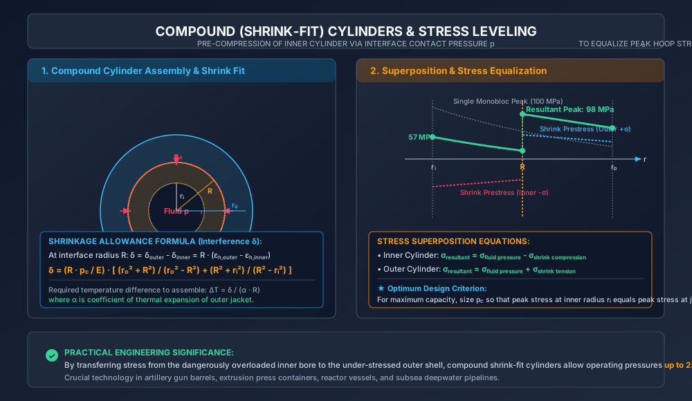
To overcome the monobloc limitation and equalize stress distribution across the entire wall thickness, compound cylinders are constructed by shrinking an outer cylinder over an inner cylinder.

       ASSEMBLY MECHANICS:
       Outer cylinder (machined with inner radius slightly smaller than R)
       is heated, slipped over the inner cylinder, and cooled.
       
       PRESTRESS STATE (Before fluid admitted, p_i = 0):
       Interface contact pressure p_c develops at junction radius R:
       - Puts INNER cylinder in hoop COMPRESSION (-σ)
       - Puts OUTER cylinder in hoop TENSION (+σ)

       WORKING STATE (Internal pressure p_i admitted):
       Superimposes tensile hoop stress across the entire wall.
       Net stress at inner bore = σ_pressure - σ_prestress  (Peak suppressed!)
       Net stress at outer jacket = σ_pressure + σ_prestress (Takes fair share!)

7.1 Lamé Analysis of Shrink-Fit Prestress (pcp_c at Junction RR)

Let:

  • Inner cylinder: internal radius rir_i, outer radius RR.
  • Outer cylinder: inner radius RR, outer radius ror_o.
  • pc=p_c = interface contact pressure developed at radius RR.
  1. Inner Cylinder Prestress (External Pressure pcp_c at r=Rr = R, p=0p = 0 at r=rir = r_i):

    • At r=rir = r_i: b1ri2−a1=0  ⟹  a1=b1ri2\frac{b_1}{r_i^2} - a_1 = 0 \implies a_1 = \frac{b_1}{r_i^2}
    • At r=Rr = R: b1R2−a1=pc  ⟹  b1(1R2−1ri2)=pc\frac{b_1}{R^2} - a_1 = p_c \implies b_1 \left( \frac{1}{R^2} - \frac{1}{r_i^2} \right) = p_c
    b1=pc1R2−1ri2=−pcR2ri2R2−ri2(Negative!)b_1 = \frac{p_c}{\frac{1}{R^2} - \frac{1}{r_i^2}} = - \frac{p_c R^2 r_i^2}{R^2 - r_i^2} \quad (\text{Negative!}) a1=b1ri2=−pcR2R2−ri2(Negative!)a_1 = \frac{b_1}{r_i^2} = - \frac{p_c R^2}{R^2 - r_i^2} \quad (\text{Negative!})

    The hoop stress in the inner cylinder is everywhere compressive:

    σh1(ri)=−2pcR2R2−ri2(Compressive)\sigma_{h1}(r_i) = - \frac{2 p_c R^2}{R^2 - r_i^2} \quad (\text{Compressive}) σh1(R)=−pc(R2+ri2R2−ri2)(Compressive)\sigma_{h1}(R) = - p_c \left( \frac{R^2 + r_i^2}{R^2 - r_i^2} \right) \quad (\text{Compressive})
  2. Outer Cylinder Prestress (Internal Pressure pcp_c at r=Rr = R, p=0p = 0 at r=ror = r_o):

    b2=pcR2ro2ro2−R2,a2=pcR2ro2−R2b_2 = \frac{p_c R^2 r_o^2}{r_o^2 - R^2}, \quad a_2 = \frac{p_c R^2}{r_o^2 - R^2}

    The hoop stress in the outer cylinder is everywhere tensile:

    σh2(R)=+pc(ro2+R2ro2−R2)(Tensile)\sigma_{h2}(R) = + p_c \left( \frac{r_o^2 + R^2}{r_o^2 - R^2} \right) \quad (\text{Tensile}) σh2(ro)=+2pcR2ro2−R2(Tensile)\sigma_{h2}(r_o) = + \frac{2 p_c R^2}{r_o^2 - R^2} \quad (\text{Tensile})

7.2 Shrinkage Allowance (Interference δ\delta)

Before assembly, the outer cylinder bore is machined smaller than the inner cylinder outside diameter by an interference amount δ\delta (radial shrinkage allowance).

At the junction radius RR:

  • The outer cylinder expands radially by δr,outer=R⋅ϵh2(R)\delta_{r,\text{outer}} = R \cdot \epsilon_{h2}(R).
  • The inner cylinder contracts radially by δr,inner=R⋅ϵh1(R)\delta_{r,\text{inner}} = R \cdot \epsilon_{h1}(R) (where ϵh1<0\epsilon_{h1} < 0).

The total radial shrinkage allowance δ\delta is:

δ=δr,outer−δr,inner=R[ϵh2(R)−ϵh1(R)]\delta = \delta_{r,\text{outer}} - \delta_{r,\text{inner}} = R [ \epsilon_{h2}(R) - \epsilon_{h1}(R) ]

Applying Hooke's law in the hoop direction at radius RR (where radial stress is −pc-p_c for both cylinders, cancelling out):

δ=RE[σh2(R)−σh1(R)]\delta = \frac{R}{E} [ \sigma_{h2}(R) - \sigma_{h1}(R) ]

Substituting the expressions for σh2(R)\sigma_{h2}(R) and σh1(R)\sigma_{h1}(R):

δ=R⋅pcE[(ro2+R2ro2−R2)+(R2+ri2R2−ri2)]\delta = \frac{R \cdot p_c}{E} \left[ \left(\frac{r_o^2 + R^2}{r_o^2 - R^2}\right) + \left(\frac{R^2 + r_i^2}{R^2 - r_i^2}\right) \right]

To assemble, the outer cylinder is heated to expand its bore:

ΔT=δα⋅R\Delta T = \frac{\delta}{\alpha \cdot R}

where α\alpha is the coefficient of thermal expansion of the outer cylinder material.


8. SVG Technical Illustrations

8.1 Lamé's Stress Distribution in Thick Cylinders

The technical graphic below illustrates the differential equilibrium of an elemental volume block and the hyperbolic stress decay profiles across the cylinder wall.

Lamé Thick Cylinder Stress Distribution

8.2 Compound Cylinder Shrink-Fit Mechanics & Stress Leveling

The diagram below shows the physical shrink-fit assembly, the shrinkage allowance equation, and the superposition stages that equalize peak hoop stress.

Compound Cylinder Shrink Fit

9. Solved Numerical Examples

Example 9.1: Monobloc Thick Hydraulic Cylinder (Lamé Analysis)

Problem Statement:
A thick-walled hydraulic cylinder of internal diameter di=200 mmd_i = 200\text{ mm} (ri=100 mmr_i = 100\text{ mm}) and external diameter do=300 mmd_o = 300\text{ mm} (ro=150 mmr_o = 150\text{ mm}) is subjected to an internal working fluid pressure of pi=40.0 MPap_i = 40.0\text{ MPa}. The external pressure is zero.

  1. Verify whether thick cylinder theory is required.
  2. Calculate the Lamé constants aa and bb.
  3. Determine the circumferential (hoop) stress and radial stress at the inner bore and outer surface.
  4. Calculate the maximum shear stress in the cylinder wall and state where it occurs.
  5. Calculate the hoop stress predicted by thin-cylinder theory and find the percentage error.

Step-by-Step Solution:

  1. Check Thickness-to-Diameter Ratio:

    Wall thickness t=ro−ri=150−100=50 mm\text{Wall thickness } t = r_o - r_i = 150 - 100 = 50\text{ mm} tdi=50 mm200 mm=0.25=14≫120(0.05)\frac{t}{d_i} = \frac{50\text{ mm}}{200\text{ mm}} = 0.25 = \frac{1}{4} \gg \frac{1}{20} \quad (0.05)

    Thick cylinder theory is strictly required.

  2. Lamé Constants (aa and bb):

    • At outer surface (r=150 mmr = 150\text{ mm}): pr=0  ⟹  b(150)2−a=0  ⟹  a=b22500p_r = 0 \implies \frac{b}{(150)^2} - a = 0 \implies a = \frac{b}{22500}
    • At inner bore (r=100 mmr = 100\text{ mm}): pr=40 MPa  ⟹  b(100)2−a=40p_r = 40\text{ MPa} \implies \frac{b}{(100)^2} - a = 40
    b10000−b22500=40  ⟹  b(22500−100002.25×108)=40\frac{b}{10000} - \frac{b}{22500} = 40 \implies b \left( \frac{22500 - 10000}{2.25 \times 10^8} \right) = 40 b(125002.25×108)=40  ⟹  b=40×2.25×10812500=720000 Nb \left( \frac{12500}{2.25 \times 10^8} \right) = 40 \implies b = \frac{40 \times 2.25 \times 10^8}{12500} = 720000\text{ N} a=b22500=72000022500=32.00 MPaa = \frac{b}{22500} = \frac{720000}{22500} = 32.00\text{ MPa}
  3. Stresses Across the Wall:

    • At Inner Bore (r=100 mmr = 100\text{ mm}): σh(ri)=bri2+a=720000(100)2+32.0=72.0+32.0=104.00 MPa (Tensile)\sigma_h(r_i) = \frac{b}{r_i^2} + a = \frac{720000}{(100)^2} + 32.0 = 72.0 + 32.0 = 104.00\text{ MPa (Tensile)} σr(ri)=−pi=−40.00 MPa (Compressive)\sigma_r(r_i) = -p_i = -40.00\text{ MPa (Compressive)}
    • At Outer Surface (r=150 mmr = 150\text{ mm}): σh(ro)=bro2+a=720000(150)2+32.0=32.0+32.0=64.00 MPa (Tensile)\sigma_h(r_o) = \frac{b}{r_o^2} + a = \frac{720000}{(150)^2} + 32.0 = 32.0 + 32.0 = 64.00\text{ MPa (Tensile)} σr(ro)=0.00 MPa\sigma_r(r_o) = 0.00\text{ MPa}
  4. Maximum Shear Stress: Maximum shear stress occurs at the inner bore where the spread between σh\sigma_h and σr\sigma_r is largest:

    τmax⁡=σh(ri)−σr(ri)2=104.00−(−40.00)2=144.002=72.00 MPa\tau_{\max} = \frac{\sigma_h(r_i) - \sigma_r(r_i)}{2} = \frac{104.00 - (-40.00)}{2} = \frac{144.00}{2} = 72.00\text{ MPa}

    (Notice: τmax⁡=bri2=72000010000=72.00 MPa\tau_{\max} = \frac{b}{r_i^2} = \frac{720000}{10000} = 72.00\text{ MPa}).

  5. Thin Cylinder Comparison:

    σh,thin=p⋅di2t=40.0×2002×50=8000100=80.00 MPa\sigma_{h,\text{thin}} = \frac{p \cdot d_i}{2 t} = \frac{40.0 \times 200}{2 \times 50} = \frac{8000}{100} = 80.00\text{ MPa} Underestimation Error=104.00−80.00104.00×100%=23.08%\text{Underestimation Error} = \frac{104.00 - 80.00}{104.00} \times 100\% = 23.08\%

    (Thin cylinder theory dangerously underestimates peak bore stress by 23.1%23.1\%, which would cause premature yielding).


Example 9.2: Subsea Pipeline Under Internal and External Pressures

Problem Statement:
A deepwater subsea steel pipeline has an internal diameter of di=240 mmd_i = 240\text{ mm} (ri=120 mmr_i = 120\text{ mm}) and an external diameter of do=360 mmd_o = 360\text{ mm} (ro=180 mmr_o = 180\text{ mm}).
It transports high-pressure gas at an internal pressure of pi=60.0 MPap_i = 60.0\text{ MPa} while situated on the seabed at a depth where hydrostatic sea water pressure is po=20.0 MPap_o = 20.0\text{ MPa}.

  1. Find the Lamé constants aa and bb.
  2. Calculate the circumferential stress and radial stress at the inner and outer surfaces.
  3. Determine the maximum shear stress in the pipe wall.

Step-by-Step Solution:

  1. Lamé Constants (aa and bb):

    • At r=120 mmr = 120\text{ mm}: b(120)2−a=60  ⟹  b14400−a=60\frac{b}{(120)^2} - a = 60 \implies \frac{b}{14400} - a = 60
    • At r=180 mmr = 180\text{ mm}: b(180)2−a=20  ⟹  b32400−a=20\frac{b}{(180)^2} - a = 20 \implies \frac{b}{32400} - a = 20 Subtracting the two equations:
    b(114400−132400)=60−20=40b \left( \frac{1}{14400} - \frac{1}{32400} \right) = 60 - 20 = 40 b(32400−1440014400×32400)=40  ⟹  b(180004.6656×108)=40b \left( \frac{32400 - 14400}{14400 \times 32400} \right) = 40 \implies b \left( \frac{18000}{4.6656 \times 10^8} \right) = 40 b=40×4.6656×10818000=1036800 Nb = \frac{40 \times 4.6656 \times 10^8}{18000} = 1036800\text{ N} a=b32400−20=103680032400−20=32.0−20.0=12.00 MPaa = \frac{b}{32400} - 20 = \frac{1036800}{32400} - 20 = 32.0 - 20.0 = 12.00\text{ MPa}
  2. Stresses Across the Wall:

    • At Inner Surface (r=120 mmr = 120\text{ mm}): σh(ri)=1036800(120)2+12.0=72.0+12.0=84.00 MPa (Tensile)\sigma_h(r_i) = \frac{1036800}{(120)^2} + 12.0 = 72.0 + 12.0 = 84.00\text{ MPa (Tensile)} σr(ri)=−pi=−60.00 MPa (Compressive)\sigma_r(r_i) = -p_i = -60.00\text{ MPa (Compressive)}
    • At Outer Surface (r=180 mmr = 180\text{ mm}): σh(ro)=1036800(180)2+12.0=32.0+12.0=44.00 MPa (Tensile)\sigma_h(r_o) = \frac{1036800}{(180)^2} + 12.0 = 32.0 + 12.0 = 44.00\text{ MPa (Tensile)} σr(ro)=−po=−20.00 MPa (Compressive)\sigma_r(r_o) = -p_o = -20.00\text{ MPa (Compressive)}
  3. Maximum Shear Stress:

    τmax⁡=bri2=103680014400=72.00 MPa\tau_{\max} = \frac{b}{r_i^2} = \frac{1036800}{14400} = 72.00\text{ MPa}

    (Or τmax⁡=σh(ri)−σr(ri)2=84.0−(−60.0)2=144.02=72.00 MPa\tau_{\max} = \frac{\sigma_h(r_i) - \sigma_r(r_i)}{2} = \frac{84.0 - (-60.0)}{2} = \frac{144.0}{2} = 72.00\text{ MPa}).


Example 9.3: Compound (Shrink-Fit) Pressure Vessel Design

Problem Statement:
A compound high-pressure container is manufactured by shrinking an outer cylinder over an inner cylinder. The geometry is:

  • Inner cylinder: internal radius ri=100 mmr_i = 100\text{ mm}, outer radius R=150 mmR = 150\text{ mm}.
  • Outer cylinder: internal radius R=150 mmR = 150\text{ mm}, external radius ro=200 mmr_o = 200\text{ mm}. The shrinkage fit produces an interface contact pressure of pc=12.0 MPap_c = 12.0\text{ MPa} at the junction radius R=150 mmR = 150\text{ mm}.
    Young's modulus of steel is E=200 GPa=2.0×10⁵ MPaE = 200\text{ GPa} = 2.0 \times 10^5\text{ MPa}.
    An internal fluid pressure of pi=60.0 MPap_i = 60.0\text{ MPa} is then admitted into the assembled compound cylinder.
  1. Calculate the hoop stresses in both cylinders due to the shrink fit alone.
  2. Calculate the hoop stresses across the compound cylinder due to internal fluid pressure alone.
  3. Determine the final resultant hoop stresses at the inner bore (r=100 mmr = 100\text{ mm}), junction (R=150 mmR = 150\text{ mm}), and outer surface (r=200 mmr = 200\text{ mm}).
  4. Calculate the required radial shrinkage allowance δ\delta (interference).
  5. Compare the peak stress in the compound cylinder with that in an equivalent single monolithic cylinder of the same dimensions.

Step-by-Step Solution:

  1. Part A: Shrink-Fit Stresses (pc=12.0 MPap_c = 12.0\text{ MPa} at R=150 mmR = 150\text{ mm}):

    • Inner Cylinder (ri=100 mm,R=150 mmr_i = 100\text{ mm}, R = 150\text{ mm}, external p=12 MPap = 12\text{ MPa}, internal p=0p = 0): b1=pc1R2−1ri2=12122500−110000=12−125002.25×108=−216000 Nb_1 = \frac{p_c}{\frac{1}{R^2} - \frac{1}{r_i^2}} = \frac{12}{\frac{1}{22500} - \frac{1}{10000}} = \frac{12}{\frac{-12500}{2.25 \times 10^8}} = -216000\text{ N} a1=b1ri2=−21600010000=−21.60 MPaa_1 = \frac{b_1}{r_i^2} = \frac{-216000}{10000} = -21.60\text{ MPa}
      • At r=100 mmr = 100\text{ mm}: σh1(100)=−21600010000+(−21.60)=−21.60−21.60=−43.20 MPa (Compression)\sigma_{h1}(100) = \frac{-216000}{10000} + (-21.60) = -21.60 - 21.60 = -43.20\text{ MPa (Compression)}
      • At r=150 mmr = 150\text{ mm}: σh1(150)=−21600022500+(−21.60)=−9.60−21.60=−31.20 MPa (Compression)\sigma_{h1}(150) = \frac{-216000}{22500} + (-21.60) = -9.60 - 21.60 = -31.20\text{ MPa (Compression)}
    • Outer Cylinder (R=150 mm,ro=200 mmR = 150\text{ mm}, r_o = 200\text{ mm}, internal p=12 MPap = 12\text{ MPa}, external p=0p = 0): b2=pc1R2−1ro2=12122500−140000=12175009×108=12×9×10817500=617142.86 Nb_2 = \frac{p_c}{\frac{1}{R^2} - \frac{1}{r_o^2}} = \frac{12}{\frac{1}{22500} - \frac{1}{40000}} = \frac{12}{\frac{17500}{9 \times 10^8}} = \frac{12 \times 9 \times 10^8}{17500} = 617142.86\text{ N} a2=b2ro2=617142.8640000=15.4286 MPaa_2 = \frac{b_2}{r_o^2} = \frac{617142.86}{40000} = 15.4286\text{ MPa}
      • At r=150 mmr = 150\text{ mm}: σh2(150)=617142.8622500+15.4286=27.4286+15.4286=+42.86 MPa (Tension)\sigma_{h2}(150) = \frac{617142.86}{22500} + 15.4286 = 27.4286 + 15.4286 = +42.86\text{ MPa (Tension)}
      • At r=200 mmr = 200\text{ mm}: σh2(200)=617142.8640000+15.4286=15.4286+15.4286=+30.86 MPa (Tension)\sigma_{h2}(200) = \frac{617142.86}{40000} + 15.4286 = 15.4286 + 15.4286 = +30.86\text{ MPa (Tension)}
  2. Part B: Stresses Due to Internal Pressure Alone (pi=60 MPap_i = 60\text{ MPa} from ri=100r_i = 100 to ro=200r_o = 200): Treating the assembled cylinders as a single solid unit:

    bp=piri2ro2ro2−ri2=60×(100)2×(200)2(200)2−(100)2=60×10000×4000030000=800000 Nb_p = \frac{p_i r_i^2 r_o^2}{r_o^2 - r_i^2} = \frac{60 \times (100)^2 \times (200)^2}{(200)^2 - (100)^2} = \frac{60 \times 10000 \times 40000}{30000} = 800000\text{ N} ap=piri2ro2−ri2=60×1000030000=20.00 MPaa_p = \frac{p_i r_i^2}{r_o^2 - r_i^2} = \frac{60 \times 10000}{30000} = 20.00\text{ MPa}
    • At r=100 mmr = 100\text{ mm}: σhp(100)=80000010000+20.0=80.0+20.0=+100.00 MPa (Tension)\sigma_{hp}(100) = \frac{800000}{10000} + 20.0 = 80.0 + 20.0 = +100.00\text{ MPa (Tension)}
    • At R=150 mmR = 150\text{ mm}: σhp(150)=80000022500+20.0=35.56+20.0=+55.56 MPa (Tension)\sigma_{hp}(150) = \frac{800000}{22500} + 20.0 = 35.56 + 20.0 = +55.56\text{ MPa (Tension)}
    • At r=200 mmr = 200\text{ mm}: σhp(200)=80000040000+20.0=20.0+20.0=+40.00 MPa (Tension)\sigma_{hp}(200) = \frac{800000}{40000} + 20.0 = 20.0 + 20.0 = +40.00\text{ MPa (Tension)}
  3. Part C: Resultant Combined Working Stresses (Superposition):

    • Inner Cylinder:
      • At inner bore (r=100 mmr = 100\text{ mm}): σh,res(100)=−43.20+100.00=+56.80 MPa (Tension)\sigma_{h,\text{res}}(100) = -43.20 + 100.00 = +56.80\text{ MPa (Tension)}
      • At junction inside (r=150− mmr = 150^-\text{ mm}): σh,res(150−)=−31.20+55.56=+24.36 MPa (Tension)\sigma_{h,\text{res}}(150^-) = -31.20 + 55.56 = +24.36\text{ MPa (Tension)}
    • Outer Cylinder:
      • At junction outside (r=150+ mmr = 150^+\text{ mm}): σh,res(150+)=+42.86+55.56=+98.42 MPa (Tension)\sigma_{h,\text{res}}(150^+) = +42.86 + 55.56 = +98.42\text{ MPa (Tension)}
      • At outer surface (r=200 mmr = 200\text{ mm}): σh,res(200)=+30.86+40.00=+70.86 MPa (Tension)\sigma_{h,\text{res}}(200) = +30.86 + 40.00 = +70.86\text{ MPa (Tension)}
  4. Radial Shrinkage Allowance (δ\delta):

    δ=RE[σh2(R)−σh1(R)]=150 mm200000 MPa[42.86−(−31.20)] MPa\delta = \frac{R}{E} [ \sigma_{h2}(R) - \sigma_{h1}(R) ] = \frac{150\text{ mm}}{200000\text{ MPa}} [ 42.86 - (-31.20) ]\text{ MPa} δ=(7.5×10−4)×(74.06)=0.055545 mm≈55.55 μm\delta = (7.5 \times 10^{-4}) \times (74.06) = 0.055545\text{ mm} \approx 55.55\ \mu\text{m}
  5. Structural Performance Comparison:

    • Single Monolithic Cylinder peak tensile stress (at bore): σh,max⁡=100.00 MPa\sigma_{h,\max} = 100.00\text{ MPa}.
    • Compound Cylinder bore stress: σh,bore=56.80 MPa\sigma_{h,\text{bore}} = 56.80\text{ MPa}.
    Stress Reduction at Inner Bore=100.00−56.80100.00×100%=43.20%\text{Stress Reduction at Inner Bore} = \frac{100.00 - 56.80}{100.00} \times 100\% = 43.20\%

(Engineering Conclusion: Shrink fitting dramatically lowers the stress at the critical inner bore from 100.0 MPa100.0\text{ MPa} to 56.80 MPa56.80\text{ MPa}, leveling the stress curve so that the outer material carries its fair share of load (98.42 MPa98.42\text{ MPa})).


10. Indian Standard Code Provisions & Engineering Practice

  1. IS 2825:1969 (Code for Unfired Pressure Vessels — Section 3):

    • Mandates thick cylinder Lamé calculations whenever t/di>0.10t / d_i > 0.10.
    • Specifies allowable design stress f=min⁡(fy/1.5,fu/2.4)f = \min(f_y / 1.5, f_u / 2.4) for forged high-pressure carbon and alloy steel shells.
    • For thick-walled forged vessels, ultrasonic testing (UT) throughout 100% of the volume is mandatory to detect laminar defects.
  2. ASME BPVC Section VIII, Division 2 & 3 (Alternative Rules for High Pressure):

    • Division 3 governs vessels operating at pressures above 70 MPa70\text{ MPa} (10,000 psi10,000\text{ psi}).
    • Mandates non-linear elastic-plastic analysis, autofrettage prestressing, and fracture mechanics fatigue crack growth verification.
  3. Autofrettage Industrial Process:

    • An alternative to shrink fitting: a single thick monobloc cylinder is subjected to an internal hydraulic pressure so high that the inner layers yield plastically while outer layers remain elastic.
    • When pressure is released, the elastically strained outer layers spring back, clamping the permanently stretched inner bore in heavy residual compression.
    • Autofrettage achieves the exact same compressive prestress as compound cylinders without requiring machining and heat shrink assembly.

11. Common Misconceptions & High-Yield Exam Traps

  1. Forgetting that Radial Stress is Compressive (Negative):

    • Trap: Adding radial stress as a positive value in Mohr's circle or shear stress: τ=σh−σr2=σh−p2\tau = \frac{\sigma_h - \sigma_r}{2} = \frac{\sigma_h - p}{2}.
    • Correction: In Lamé theory, radial stress is compressive: σr=−p\sigma_r = -p. Therefore, τmax⁡=σh−(−p)2=σh+p2=br2\tau_{\max} = \frac{\sigma_h - (-p)}{2} = \frac{\sigma_h + p}{2} = \frac{b}{r^2}.
  2. Assuming σh,max⁡\sigma_{h,\max} Can be Reduced Below pip_i by Increasing Thickness:

    • Trap: Thinking an infinitely thick cylinder will have zero hoop stress.
    • Correction: The limit as ro→∞r_o \to \infty is σh,max⁡→pi\sigma_{h,\max} \to p_i. Hoop stress at the bore is strictly greater than internal pressure (>pi> p_i) for any finite thickness!
  3. Applying Thin Cylinder Formula to Thick Shells:

    • Trap: Using σh=pd2t\sigma_h = \frac{p d}{2 t} on thick cylinders.
    • Correction: The thin cylinder formula computes the average stress across the thickness, underestimating the inner peak by 20%20\% to 50%50\%.
  4. Shrinkage Allowance Sign Confusion:

    • Trap: Subtracting magnitudes instead of algebraic values: δ=RE(σ2−σ1)\delta = \frac{R}{E}(\sigma_2 - \sigma_1) where σ1\sigma_1 is already negative.
    • Correction: Because inner prestress σ1\sigma_1 is compressive (negative), σ2−σ1=σ2−(−σ1)=σ2+∣σ1∣\sigma_2 - \sigma_1 = \sigma_2 - (-\sigma_1) = \sigma_2 + |\sigma_1|. The interference is the sum of outer expansion and inner contraction.
  5. Location of Maximum Shear Stress:

    • Trap: Believing maximum shear stress occurs at the outer surface.
    • Correction: Both hoop tension σh\sigma_h and radial compression ∣σr∣|\sigma_r| are maximized at the inner radius r=rir = r_i. Therefore, τmax⁡=br2\tau_{\max} = \frac{b}{r^2} is strictly maximum at the inner bore.

12. Previous Year Competitive Exam Questions

Question 1 (GATE CE — 2 Marks)

A thick cylinder of inner radius rir_i and outer radius ror_o is subjected to an internal fluid pressure pip_i. If the maximum circumferential stress is three times the internal pressure, the ratio of outer radius to inner radius (ro/rir_o / r_i) is:

  • (A) 2\sqrt{2}
  • (B) 3\sqrt{3}
  • (C) 2.02.0
  • (D) 5\sqrt{5}

Answer: (A)
Solution:
For internal pressure only: σh,max⁡=pi(ro2+ri2ro2−ri2)\sigma_{h,\max} = p_i \left( \frac{r_o^2 + r_i^2}{r_o^2 - r_i^2} \right).
Given σh,max⁡=3pi\sigma_{h,\max} = 3 p_i:

3pi=pi(ro2+ri2ro2−ri2)  ⟹  3(ro2−ri2)=ro2+ri23 p_i = p_i \left( \frac{r_o^2 + r_i^2}{r_o^2 - r_i^2} \right) \implies 3 (r_o^2 - r_i^2) = r_o^2 + r_i^2 3ro2−3ri2=ro2+ri2  ⟹  2ro2=4ri2  ⟹  ro2ri2=2  ⟹  rori=2≈1.4143 r_o^2 - 3 r_i^2 = r_o^2 + r_i^2 \implies 2 r_o^2 = 4 r_i^2 \implies \frac{r_o^2}{r_i^2} = 2 \implies \frac{r_o}{r_i} = \sqrt{2} \approx 1.414

Question 2 (UPSC ESE)

In a thick cylinder subjected to internal pressure pp, the radial stress σr\sigma_r and circumferential stress σh\sigma_h at any radius rr satisfy which of the following relations?

  • (A) σh−σr=constant\sigma_h - \sigma_r = \text{constant}
  • (B) σh+σr=constant\sigma_h + \sigma_r = \text{constant}
  • (C) σh⋅σr=constant\sigma_h \cdot \sigma_r = \text{constant}
  • (D) σh/σr=constant\sigma_h / \sigma_r = \text{constant}

Answer: (B)
Solution:
From plane strain compatibility (ϵL=constant\epsilon_L = \text{constant}), σh+σr=2a=constant\sigma_h + \sigma_r = 2a = \text{constant}.


Question 3 (SSC JE)

The variation of circumferential hoop stress across the thickness of a thick cylinder subjected to internal pressure is:

  • (A) Linear
  • (B) Parabolic
  • (C) Hyperbolic
  • (D) Uniform

Answer: (C)
Solution:
σh(r)=br2+a\sigma_h(r) = \frac{b}{r^2} + a. The stress varies inversely as the square of radius (1/r21/r^2), which is a hyperbolic variation.


Question 4 (State AE)

A compound cylinder is formed by shrink-fitting. The hoop stress induced in the inner cylinder due to shrink fit alone is:

  • (A) Tensile throughout
  • (B) Compressive throughout
  • (C) Tensile at inner surface, compressive at outer surface
  • (D) Zero

Answer: (B)
Solution:
The shrink-fit interface pressure pcp_c acts externally on the inner cylinder, inducing compressive hoop stress everywhere across its wall.
13. Comprehensive Summary & Formula Sheet

Parameter / Expression Mathematical Formula Physical Significance
Thick Cylinder Criteria t/di>1/20t / d_i > 1/20 (t/ri>0.10t / r_i > 0.10) Non-uniform hoop stress, non-zero radial stress
Lamé Hoop Stress Equation σh(r)=br2+a\sigma_h(r) = \frac{b}{r^2} + a Hyperbolic decay across wall thickness
Lamé Radial Pressure Equation pr(r)=br2−ap_r(r) = \frac{b}{r^2} - a Compressive fluid pressure (pr=−σrp_r = -\sigma_r)
Lamé Radial Stress Equation σr(r)=a−br2\sigma_r(r) = a - \frac{b}{r^2} True algebraic stress (σr≤0\sigma_r \le 0)
Sum of Stresses Invariant σh+σr=2a=constant\sigma_h + \sigma_r = 2a = \text{constant} Compatibility for plane longitudinal sections
Internal Pressure Only: bb b=piri2ro2ro2−ri2b = \frac{p_i r_i^2 r_o^2}{r_o^2 - r_i^2} Lamé constant bb
Internal Pressure Only: aa a=piri2ro2−ri2a = \frac{p_i r_i^2}{r_o^2 - r_i^2} Lamé constant a=σLa = \sigma_L
Max Hoop Stress (Inner Bore) σh,max⁡=pi(ro2+ri2ro2−ri2)\sigma_{h,\max} = p_i \left( \frac{r_o^2 + r_i^2}{r_o^2 - r_i^2} \right) Highest stress in monolithic cylinder
Min Hoop Stress (Outer Surface) σh,min⁡=pi(2ri2ro2−ri2)\sigma_{h,\min} = p_i \left( \frac{2 r_i^2}{r_o^2 - r_i^2} \right) Lowest hoop stress in cylinder wall
Maximum Shear Stress τmax⁡(r)=br2  ⟹  τmax⁡,bore=piro2ro2−ri2\tau_{\max}(r) = \frac{b}{r^2} \implies \tau_{\max,\text{bore}} = \frac{p_i r_o^2}{r_o^2 - r_i^2} Governs Tresca yield at inner bore
Monobloc Limit lim⁡ro→∞σh,max⁡=pi\lim_{r_o \to \infty} \sigma_{h,\max} = p_i Monobloc cannot contain pi>σallowp_i > \sigma_{\text{allow}}
Shrinkage Allowance (δ\delta) δ=RpcE[ro2+R2ro2−R2+R2+ri2R2−ri2]\delta = \frac{R p_c}{E} \left[ \frac{r_o^2 + R^2}{r_o^2 - R^2} + \frac{R^2 + r_i^2}{R^2 - r_i^2} \right] Total radial interference at junction RR
Shrink Fit Assembly Temp ΔT=δαR\Delta T = \frac{\delta}{\alpha R} Required heating of outer jacket