SOM-02-02 Chapter 02 · Principal Stresses and Strains

Principal Stresses, Principal Planes & Maximum In-Plane Shear

In this chapter (5 topics)
On this page
  1. 1. Metadata & Syllabus Mapping
  2. Official Examination Syllabus Mapping
  3. 2. Introduction & Physical Mechanics
  4. Definitions
  5. 3. Mathematical Formulations & Derivations
  6. 3.1 Derivation of Principal Planes (τθ = 0)
  7. 3.2 Extreme Values of Normal Stress
  8. ⭐ The Stationary Stress Theorem
  9. 3.3 Derivation of Principal Stress Magnitudes (σ1, σ2)
  10. 3.4 Maximum In-Plane Shear Stress (τmax)
  11. ⚠️ Critical Engineering Takeaway
  12. 3.5 In-Plane vs. Absolute 3D Maximum Shear Stress (τabs, max)
  13. 3.6 Combined Bending and Torsion in Circular Shafts
  14. 4. Engineering Assumptions & Limitations
  15. 5. Technical Diagrams
  16. Diagram 1: Principal Planes and Principal Stresses Element
  17. Diagram 2: Maximum In-Plane and Absolute Shear Stress Element
  18. 6. Solved Numerical Examples
  19. Example 2.1: Principal Stresses with Opposite Signs
  20. Example 2.2: Principal Stresses with Identical Signs (The Critical 3D Trap!)
  21. Example 2.3: Circular Shaft under Combined Bending and Torsion
  22. 7. Practical Engineering Applications & Field Case Studies
  23. 1. Diagonal Tension and Web Shear in Reinforced Concrete Beams (IS 456:2000 Cl. 40)
  24. 2. Failure Trajectories in Structural Members (Stress Trajectories)
  25. 3. Thin Cylindrical and Spherical Pressure Shells (IS 2825)
  26. 8. Comparison Tables
  27. Table 1: Principal Planes vs. Maximum Shear Planes
  28. Table 2: In-Plane Maximum Shear vs. Absolute 3D Maximum Shear
  29. 9. Key Engineering Facts & Exam Takeaways
  30. 10. Common Pitfalls, Traps & Anti-Patterns
  31. 11. Standards & Code Provisions
  32. IS 456:2000 (Plain and Reinforced Concrete - Code of Practice)
  33. IS 800:2007 (General Construction in Steel - Code of Practice)
  34. 12. Comprehensive Formula Box & Practice Problems
  35. Master Formula Summary
  36. Practice Problems

1. Metadata & Syllabus Mapping

Attribute Specification
Topic ID SOM-02-02
Module / Subject Subject 02: Strength of Materials (notes/strength_of_materials/)
Chapter Chapter 02: Principal Stresses and Strains (02_principal_stresses_and_strains)
Target Examinations GATE CE, UPSC ESE, SSC JE, RRB JE, State AE, State JE
Prerequisites SOM-01-01 (Stress and Strain), SOM-02-01 (Stress Transformation on Oblique Planes)
Primary Code References IS 456:2000 (Shear and Diagonal Tension in Concrete), IS 800:2007 (Combined Bending & Torsion in Steel), IS 2825
Verification Gate Level 1 through Level 7 Quality Standards

Official Examination Syllabus Mapping

Website note: this mapping is from the author’s notes. It has not been checked against the official notification for each examination; confirm the current syllabus with the examining body.

- GATE Civil Engineering: Solid Mechanics — Principal stresses and principal planes; maximum shear stress; in-plane vs absolute maximum shear; combined bending and torsion in shafts.
- UPSC ESE (Engineering Services): Paper-I Building Materials and Structural Analysis — Determination of principal stresses and planes; orientation of maximum shear planes; 3D stress states.
- SSC JE / RRB JE / State AE: Principal planes; zero shear stress planes; major and minor principal stresses; equivalent bending moment and equivalent twisting moment.

2. Introduction & Physical Mechanics

In any general state of plane stress, the normal stress (σθ\sigma_\theta) and shear stress (τθ\tau_\theta) acting across an internal cut vary continuously as the inclination angle θ\theta is rotated through 360∘360^\circ.

For structural engineers designing safety-critical components (such as concrete beams, steel bridge girders, drive shafts, or pressure vessels), two questions are of paramount importance:

  1. What is the maximum normal stress developed at this point, and on which plane does it act? (Governs tensile fracture in brittle materials such as concrete, rock, and cast iron).
  2. What is the maximum shear stress developed at this point, and on which plane does it act? (Governs plastic yielding and ductile slip in structural steel, aluminum, and soils).

Definitions

  • Principal Planes: Planes on which the shear stress is identically zero (τ=0\tau = 0).
  • Principal Stresses: The normal stresses acting across the principal planes. Because shear stress vanishes on these planes, the normal stresses reach their global stationary extreme values (the absolute maximum and minimum normal stresses possible at that point).
  • Major Principal Stress (σ1\sigma_1): The algebraically largest normal stress.
  • Minor Principal Stress (σ2\sigma_2): The algebraically smallest normal stress.
  • Maximum In-Plane Shear Stress (τmax⁡\tau_{\max}): The maximum shear stress occurring on any plane perpendicular to the xyxy-plane.

3. Mathematical Formulations & Derivations

3.1 Derivation of Principal Planes (τθ=0\tau_\theta = 0)

From Topic SOM-02-01, the shear stress on an oblique plane inclined at angle θ\theta counterclockwise from the vertical plane is:

τθ=−(σx−σy2)sin⁡2θ+τxycos⁡2θ(Eq. 2.1)\tau_\theta = -\left(\frac{\sigma_x - \sigma_y}{2}\right)\sin 2\theta + \tau_{xy}\cos 2\theta \tag{Eq. 2.1}

By definition, on a principal plane (θ=θp\theta = \theta_p), the shear stress must vanish:

τθ=0  ⟹  −(σx−σy2)sin⁡2θp+τxycos⁡2θp=0\tau_\theta = 0 \implies -\left(\frac{\sigma_x - \sigma_y}{2}\right)\sin 2\theta_p + \tau_{xy}\cos 2\theta_p = 0 (σx−σy2)sin⁡2θp=τxycos⁡2θp\left(\frac{\sigma_x - \sigma_y}{2}\right)\sin 2\theta_p = \tau_{xy}\cos 2\theta_p

Dividing both sides by cos⁡2θp\cos 2\theta_p and (σx−σy2)\left(\frac{\sigma_x - \sigma_y}{2}\right):

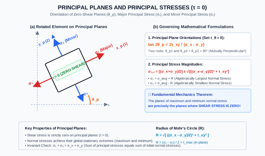
tan⁡2θp=τxyσx−σy2=2τxyσx−σy(Eq. 2.2)\mathbf{\tan 2\theta_p = \frac{\tau_{xy}}{\frac{\sigma_x - \sigma_y}{2}} = \frac{2\tau_{xy}}{\sigma_x - \sigma_y}} \tag{Eq. 2.2}

Orthogonality of Principal Planes

Because the tangent function has a fundamental period of 180∘180^\circ (π\pi radians):

tan⁡2θp2=tan⁡(2θp1+180∘)  ⟹  2θp2=2θp1+180∘  ⟹  θp2=θp1+90∘(Eq. 2.3)\tan 2\theta_{p2} = \tan(2\theta_{p1} + 180^\circ) \implies 2\theta_{p2} = 2\theta_{p1} + 180^\circ \implies \mathbf{\theta_{p2} = \theta_{p1} + 90^\circ} \tag{Eq. 2.3}

Fundamental Theorem: At every point in a continuous body, there exist two mutually perpendicular principal planes on which the shear stress is identically zero.


3.2 Extreme Values of Normal Stress

Recall the normal stress transformation equation:

σθ=(σx+σy2)+(σx−σy2)cos⁡2θ+τxysin⁡2θ(Eq. 2.4)\sigma_\theta = \left(\frac{\sigma_x + \sigma_y}{2}\right) + \left(\frac{\sigma_x - \sigma_y}{2}\right)\cos 2\theta + \tau_{xy}\sin 2\theta \tag{Eq. 2.4}

To find the orientations θ\theta where σθ\sigma_\theta reaches its stationary extremes (maximum or minimum), differentiate with respect to θ\theta and equate to zero:

dσθdθ=−2(σx−σy2)sin⁡2θ+2τxycos⁡2θ=0\frac{d\sigma_\theta}{d\theta} = -2\left(\frac{\sigma_x - \sigma_y}{2}\right)\sin 2\theta + 2\tau_{xy}\cos 2\theta = 0

Dividing by 22:

−(σx−σy2)sin⁡2θ+τxycos⁡2θ=0-\left(\frac{\sigma_x - \sigma_y}{2}\right)\sin 2\theta + \tau_{xy}\cos 2\theta = 0

Comparing this expression directly with Eq. (2.1), we observe that:

dσθdθ=2τθ=0  ⟹  τθ=0(Eq. 2.5)\frac{d\sigma_\theta}{d\theta} = 2\tau_\theta = 0 \implies \mathbf{\tau_\theta = 0} \tag{Eq. 2.5}

⭐ The Stationary Stress Theorem

The planes of maximum and minimum normal stress are identical to the planes of zero shear stress (the principal planes)! Normal stresses reach their absolute extremes precisely where shear vanishes.


3.3 Derivation of Principal Stress Magnitudes (σ1,σ2\sigma_1, \sigma_2)

From Eq. (2.2), we construct a reference right triangle with opposite side τxy\tau_{xy} and adjacent side σx−σy2\frac{\sigma_x - \sigma_y}{2}:

Hypotenuse R=(σx−σy2)2+τxy2(Eq. 2.6)\text{Hypotenuse } R = \sqrt{\left(\frac{\sigma_x - \sigma_y}{2}\right)^2 + \tau_{xy}^2} \tag{Eq. 2.6}

The trigonometric values for 2θp2\theta_p are:

cos⁡2θp=±σx−σy2R,sin⁡2θp=±τxyR(Eq. 2.7)\cos 2\theta_p = \pm \frac{\frac{\sigma_x - \sigma_y}{2}}{R}, \qquad \sin 2\theta_p = \pm \frac{\tau_{xy}}{R} \tag{Eq. 2.7}

Substitute these into the normal stress equation Eq. (2.4):

σ1,2=(σx+σy2)+(σx−σy2)[±σx−σy2R]+τxy[±τxyR]\sigma_{1,2} = \left(\frac{\sigma_x + \sigma_y}{2}\right) + \left(\frac{\sigma_x - \sigma_y}{2}\right)\left[\pm \frac{\frac{\sigma_x - \sigma_y}{2}}{R}\right] + \tau_{xy}\left[\pm \frac{\tau_{xy}}{R}\right] σ1,2=(σx+σy2)±(σx−σy2)2+τxy2R=(σx+σy2)±R2R\sigma_{1,2} = \left(\frac{\sigma_x + \sigma_y}{2}\right) \pm \frac{\left(\frac{\sigma_x - \sigma_y}{2}\right)^2 + \tau_{xy}^2}{R} = \left(\frac{\sigma_x + \sigma_y}{2}\right) \pm \frac{R^2}{R} σ1,2=(σx+σy2)±(σx−σy2)2+τxy2(Eq. 2.8)\mathbf{\sigma_{1,2} = \left(\frac{\sigma_x + \sigma_y}{2}\right) \pm \sqrt{\left(\frac{\sigma_x - \sigma_y}{2}\right)^2 + \tau_{xy}^2}} \tag{Eq. 2.8}

Defining the Average Normal Stress:

σavg=σx+σy2(Eq. 2.9)\sigma_{\text{avg}} = \frac{\sigma_x + \sigma_y}{2} \tag{Eq. 2.9}

We obtain the canonical principal stress formulas:

σ1=σavg+R(Major Principal Stress)(Eq. 2.10a)\mathbf{\sigma_1 = \sigma_{\text{avg}} + R} \quad (\text{Major Principal Stress}) \tag{Eq. 2.10a} σ2=σavg−R(Minor Principal Stress)(Eq. 2.10b)\mathbf{\sigma_2 = \sigma_{\text{avg}} - R} \quad (\text{Minor Principal Stress}) \tag{Eq. 2.10b}

Notice that adding σ1\sigma_1 and σ2\sigma_2:

σ1+σ2=(σavg+R)+(σavg−R)=2σavg=σx+σy=I1(Eq. 2.11)\sigma_1 + \sigma_2 = (\sigma_{\text{avg}} + R) + (\sigma_{\text{avg}} - R) = 2\sigma_{\text{avg}} = \sigma_x + \sigma_y = I_1 \tag{Eq. 2.11}

This confirms the first stress invariant.


3.4 Maximum In-Plane Shear Stress (τmax⁡\tau_{\max})

To find the plane of maximum shear stress, differentiate τθ\tau_\theta with respect to θ\theta and equate to zero:

dτθdθ=−2(σx−σy2)cos⁡2θs−2τxysin⁡2θs=0\frac{d\tau_\theta}{d\theta} = -2\left(\frac{\sigma_x - \sigma_y}{2}\right)\cos 2\theta_s - 2\tau_{xy}\sin 2\theta_s = 0

Dividing by 22:

τxysin⁡2θs=−(σx−σy2)cos⁡2θs\tau_{xy}\sin 2\theta_s = -\left(\frac{\sigma_x - \sigma_y}{2}\right)\cos 2\theta_s tan⁡2θs=−σx−σy2τxy=−σx−σy2τxy=−1tan⁡2θp(Eq. 2.12)\mathbf{\tan 2\theta_s = -\frac{\frac{\sigma_x - \sigma_y}{2}}{\tau_{xy}} = -\frac{\sigma_x - \sigma_y}{2\tau_{xy}} = -\frac{1}{\tan 2\theta_p}} \tag{Eq. 2.12}

Relationship between Principal Planes and Maximum Shear Planes

Since tan⁡2θs⋅tan⁡2θp=−1\tan 2\theta_s \cdot \tan 2\theta_p = -1:

2θs=2θp±90∘  ⟹  θs=θp±45∘(Eq. 2.13)2\theta_s = 2\theta_p \pm 90^\circ \implies \mathbf{\theta_s = \theta_p \pm 45^\circ} \tag{Eq. 2.13}

Golden Rule: The planes of maximum shear stress are always inclined at exactly 45∘45^\circ to the principal planes!

Magnitude of Maximum In-Plane Shear Stress

Substituting cos⁡2θs\cos 2\theta_s and sin⁡2θs\sin 2\theta_s into the shear stress equation:

τmax⁡,in-plane=R=(σx−σy2)2+τxy2=σ1−σ22(Eq. 2.14)\mathbf{\tau_{\max, \text{in-plane}} = R = \sqrt{\left(\frac{\sigma_x - \sigma_y}{2}\right)^2 + \tau_{xy}^2} = \frac{\sigma_1 - \sigma_2}{2}} \tag{Eq. 2.14}

Accompanying Normal Stress on Maximum Shear Planes

What normal stress acts on the maximum shear planes? Substituting θs=θp+45∘\theta_s = \theta_p + 45^\circ (2θs=2θp+90∘2\theta_s = 2\theta_p + 90^\circ) into Eq. (2.4):

σs=(σx+σy2)+(σx−σy2)cos⁡(2θp+90∘)+τxysin⁡(2θp+90∘)\sigma_s = \left(\frac{\sigma_x + \sigma_y}{2}\right) + \left(\frac{\sigma_x - \sigma_y}{2}\right)\cos(2\theta_p + 90^\circ) + \tau_{xy}\sin(2\theta_p + 90^\circ) σs=σavg−(σx−σy2)sin⁡2θp+τxycos⁡2θp\sigma_s = \sigma_{\text{avg}} - \left(\frac{\sigma_x - \sigma_y}{2}\right)\sin 2\theta_p + \tau_{xy}\cos 2\theta_p

Notice that the last two terms are identically equal to τθp=0\tau_{\theta_p} = 0! Therefore:

σs=σavg=σx+σy2=σ1+σ22(Eq. 2.15)\mathbf{\sigma_s = \sigma_{\text{avg}} = \frac{\sigma_x + \sigma_y}{2} = \frac{\sigma_1 + \sigma_2}{2}} \tag{Eq. 2.15}

⚠️ Critical Engineering Takeaway

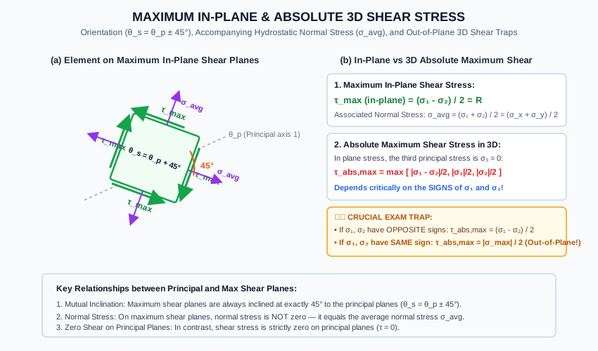
The normal stress on the planes of maximum shear stress is NOT ZERO! It is equal to the average normal stress (σavg\sigma_{\text{avg}}) acting uniformly on all four faces of the maximum shear element.


3.5 In-Plane vs. Absolute 3D Maximum Shear Stress (τabs, max\tau_{\text{abs, max}})

In a state of 2D plane stress, the out-of-plane stress components are zero:

σ3=0(Eq. 2.16)\sigma_3 = 0 \tag{Eq. 2.16}

Thus, at any point in a plane stress body, the three 3D principal stresses are:

σI=σ1,σII=σ2,σIII=σ3=0\sigma_I = \sigma_1, \quad \sigma_{II} = \sigma_2, \quad \sigma_{III} = \sigma_3 = 0

From 3D Mohr's circle analysis, the true maximum shear stress acting on any oblique plane in 3D space is:

τabs, max=max⁡(∣σ1−σ2∣2,∣σ1−σ3∣2,∣σ2−σ3∣2)=max⁡(∣σ1−σ2∣2,∣σ1∣2,∣σ2∣2)(Eq. 2.17)\mathbf{\tau_{\text{abs, max}} = \max\left(\frac{|\sigma_1 - \sigma_2|}{2}, \frac{|\sigma_1 - \sigma_3|}{2}, \frac{|\sigma_2 - \sigma_3|}{2}\right) = \max\left(\frac{|\sigma_1 - \sigma_2|}{2}, \frac{|\sigma_1|}{2}, \frac{|\sigma_2|}{2}\right)} \tag{Eq. 2.17}

The Two Distinct Cases:

  1. Case A: Principal stresses σ1\sigma_1 and σ2\sigma_2 have OPPOSITE signs (σ1>0\sigma_1 > 0 and σ2<0\sigma_2 < 0):

    τabs, max=σ1−σ22=τmax⁡,in-plane(Eq. 2.18a)\tau_{\text{abs, max}} = \frac{\sigma_1 - \sigma_2}{2} = \tau_{\max, \text{in-plane}} \tag{Eq. 2.18a}

    (The in-plane maximum shear stress governs globally).

  2. Case B: Principal stresses σ1\sigma_1 and σ2\sigma_2 have the SAME sign (both tension or both compression): Let σ1>σ2>0\sigma_1 > \sigma_2 > 0 (both tensile). Then:

    σ1−σ22<σ1−02=σ12\frac{\sigma_1 - \sigma_2}{2} < \frac{\sigma_1 - 0}{2} = \frac{\sigma_1}{2} τabs, max=σ12=σmax⁡2>τmax⁡,in-plane(Eq. 2.18b)\mathbf{\tau_{\text{abs, max}} = \frac{\sigma_1}{2} = \frac{\sigma_{\max}}{2}} > \tau_{\max, \text{in-plane}} \tag{Eq. 2.18b}

    (The true maximum shear stress occurs on an out-of-plane plane inclined at 45∘45^\circ to the zz-axis!).

Classic Competitive Exam Trap: In a thin spherical pressure vessel with biaxial tension σ1=σ2=σ\sigma_1 = \sigma_2 = \sigma, the in-plane maximum shear stress is σ−σ2=0\frac{\sigma - \sigma}{2} = 0. However, the absolute 3D maximum shear stress is τabs, max=σ−02=σ2\tau_{\text{abs, max}} = \frac{\sigma - 0}{2} = \frac{\sigma}{2}!


3.6 Combined Bending and Torsion in Circular Shafts

In civil and mechanical drive shafts (e.g., turbine shafts, bascule bridge hoisting shafts, crane winch drives), a circular shaft of diameter dd is subjected simultaneously to a bending moment MM and a torsional twisting moment TT.

Surface Stress State:

  • Maximum bending normal stress at outermost fibers: σx=MyI=M(d/2)πd464=32Mπd3=MZb(Eq. 2.19)\sigma_x = \frac{M y}{I} = \frac{M (d/2)}{\frac{\pi d^4}{64}} = \frac{32 M}{\pi d^3} = \frac{M}{Z_b} \tag{Eq. 2.19}
  • Maximum torsional shear stress at outermost fibers: τxy=TrJ=T(d/2)πd432=16Tπd3=TZp=T2Zb(Eq. 2.20)\tau_{xy} = \frac{T r}{J} = \frac{T (d/2)}{\frac{\pi d^4}{32}} = \frac{16 T}{\pi d^3} = \frac{T}{Z_p} = \frac{T}{2 Z_b} \tag{Eq. 2.20}
  • Transverse normal stress: σy=0\sigma_y = 0.

Principal Stresses:

σ1,2=σx2±(σx2)2+τxy2\sigma_{1,2} = \frac{\sigma_x}{2} \pm \sqrt{\left(\frac{\sigma_x}{2}\right)^2 + \tau_{xy}^2}

Substitute σx=32Mπd3\sigma_x = \frac{32 M}{\pi d^3} and τxy=16Tπd3\tau_{xy} = \frac{16 T}{\pi d^3}:

σ1,2=16Mπd3±(16Mπd3)2+(16Tπd3)2=16πd3[M±M2+T2]\sigma_{1,2} = \frac{16 M}{\pi d^3} \pm \sqrt{\left(\frac{16 M}{\pi d^3}\right)^2 + \left(\frac{16 T}{\pi d^3}\right)^2} = \frac{16}{\pi d^3}\left[M \pm \sqrt{M^2 + T^2}\right] σ1,2=32πd3[12(M±M2+T2)](Eq. 2.21)\mathbf{\sigma_{1,2} = \frac{32}{\pi d^3}\left[\frac{1}{2}\left(M \pm \sqrt{M^2 + T^2}\right)\right]} \tag{Eq. 2.21}

Defining the Equivalent Bending Moment (MeM_e):

Me=12(M+M2+T2)(Eq. 2.22)\mathbf{M_e = \frac{1}{2}\left(M + \sqrt{M^2 + T^2}\right)} \tag{Eq. 2.22}

The major principal tensile stress is:

σ1=32Meπd3=MeZb(Eq. 2.23)\mathbf{\sigma_1 = \frac{32 M_e}{\pi d^3} = \frac{M_e}{Z_b}} \tag{Eq. 2.23}

Maximum Shear Stress:

τmax⁡=(σx2)2+τxy2=16πd3M2+T2\tau_{\max} = \sqrt{\left(\frac{\sigma_x}{2}\right)^2 + \tau_{xy}^2} = \frac{16}{\pi d^3}\sqrt{M^2 + T^2}

Defining the Equivalent Twisting Moment (TeT_e):

Te=M2+T2(Eq. 2.24)\mathbf{T_e = \sqrt{M^2 + T^2}} \tag{Eq. 2.24}

The maximum shear stress is:

τmax⁡=16Teπd3=TeZp(Eq. 2.25)\mathbf{\tau_{\max} = \frac{16 T_e}{\pi d^3} = \frac{T_e}{Z_p}} \tag{Eq. 2.25}

4. Engineering Assumptions & Limitations

  1. Continuum Differential Element: Stress distributions across the infinitesimal element are uniform, ensuring true point-stress representation.
  2. Homogeneous, Isotropic Elastic Material: Hooke's Law holds and material response is independent of direction.
  3. Plane Stress Boundary Conditions: σz=τxz=τyz=0\sigma_z = \tau_{xz} = \tau_{yz} = 0. For thick solid components where plane strain or triaxial stress exists, 3D tensor equations must be employed.
  4. Sign Convention Consistency: θp\theta_p is positive counterclockwise from the vertical plane.

5. Technical Diagrams

Diagram 1: Principal Planes and Principal Stresses Element

The following vector diagram details the rotated principal stress element, the zero-shear condition on all four faces, and the orientation angle θp\theta_p.

Principal Planes and Principal Stresses

Diagram 2: Maximum In-Plane and Absolute Shear Stress Element

The vector diagram below illustrates the maximum shear stress element rotated at 45∘45^\circ to the principal planes, the accompanying average normal stress σavg\sigma_{\text{avg}}, and the out-of-plane 3D shear comparison.

Maximum Shear Stress Planes Element

6. Solved Numerical Examples

Example 2.1: Principal Stresses with Opposite Signs

At a point on the surface of a crane hook subjected to combined axial tension and bending, the state of plane stress is:

  • σx=+80 MPa\sigma_x = +80\text{ MPa} (Tension)
  • σy=−20 MPa\sigma_y = -20\text{ MPa} (Compression)
  • τxy=+40 MPa\tau_{xy} = +40\text{ MPa}

Determine:

  1. The orientation of the principal planes (θp1,θp2\theta_{p1}, \theta_{p2}).
  2. The magnitudes of the major and minor principal stresses (σ1,σ2\sigma_1, \sigma_2).
  3. The maximum in-plane shear stress and the orientation of its planes.
  4. The absolute 3D maximum shear stress.
Given:
σx = +80 MPa
σy = -20 MPa
τxy = +40 MPa

Solution:

Step 1: Compute Center and Radius of Mohr's Circle

σavg=σx+σy2=80+(−20)2=602=+30 MPa\sigma_{\text{avg}} = \frac{\sigma_x + \sigma_y}{2} = \frac{80 + (-20)}{2} = \frac{60}{2} = +30\text{ MPa} σdiff=σx−σy2=80−(−20)2=1002=+50 MPa\sigma_{\text{diff}} = \frac{\sigma_x - \sigma_y}{2} = \frac{80 - (-20)}{2} = \frac{100}{2} = +50\text{ MPa} R=σdiff2+τxy2=502+402=2500+1600=4100≈64.03 MPaR = \sqrt{\sigma_{\text{diff}}^2 + \tau_{xy}^2} = \sqrt{50^2 + 40^2} = \sqrt{2500 + 1600} = \sqrt{4100} \approx \mathbf{64.03\text{ MPa}}

Step 2: Principal Planes Orientation

tan⁡2θp=2τxyσx−σy=2(40)80−(−20)=80100=+0.8000\tan 2\theta_p = \frac{2\tau_{xy}}{\sigma_x - \sigma_y} = \frac{2(40)}{80 - (-20)} = \frac{80}{100} = +0.8000 2θp1=arctan⁡(0.8000)=38.66∘  ⟹  θp1=+19.33∘2\theta_{p1} = \arctan(0.8000) = 38.66^\circ \implies \mathbf{\theta_{p1} = +19.33^\circ} 2θp2=38.66∘+180∘=218.66∘  ⟹  θp2=+109.33∘(or −70.67∘)2\theta_{p2} = 38.66^\circ + 180^\circ = 218.66^\circ \implies \mathbf{\theta_{p2} = +109.33^\circ} \quad (\text{or } -70.67^\circ)

Step 3: Principal Stress Values

σ1=σavg+R=30+64.03=+94.03 MPa(Major Principal Tensile Stress)\sigma_1 = \sigma_{\text{avg}} + R = 30 + 64.03 = \mathbf{+94.03\text{ MPa} \quad (\text{Major Principal Tensile Stress})} σ2=σavg−R=30−64.03=−34.03 MPa(Minor Principal Compressive Stress)\sigma_2 = \sigma_{\text{avg}} - R = 30 - 64.03 = \mathbf{-34.03\text{ MPa} \quad (\text{Minor Principal Compressive Stress})}

Verification Check with Transformation Equation at θ=19.33∘\theta = 19.33^\circ:

σ=30+50cos⁡(38.66∘)+40sin⁡(38.66∘)=30+50(0.7809)+40(0.6247)=30+39.04+24.99=94.03 MPa=σ1✓\sigma = 30 + 50\cos(38.66^\circ) + 40\sin(38.66^\circ) = 30 + 50(0.7809) + 40(0.6247) = 30 + 39.04 + 24.99 = 94.03\text{ MPa} = \sigma_1 \quad \checkmark

Step 4: Maximum In-Plane Shear Stress

τmax⁡,in-plane=R=σ1−σ22=94.03−(−34.03)2=128.062=64.03 MPa\tau_{\max, \text{in-plane}} = R = \frac{\sigma_1 - \sigma_2}{2} = \frac{94.03 - (-34.03)}{2} = \frac{128.06}{2} = \mathbf{64.03\text{ MPa}}

Orientation:

θs=θp1+45∘=19.33∘+45∘=+64.33∘\theta_s = \theta_{p1} + 45^\circ = 19.33^\circ + 45^\circ = \mathbf{+64.33^\circ}

Normal stress on maximum shear plane:

σs=σavg=+30.00 MPa\sigma_s = \sigma_{\text{avg}} = \mathbf{+30.00\text{ MPa}}

Step 5: Absolute 3D Maximum Shear Stress In 3D, σ3=0\sigma_3 = 0. Since σ1=+94.03 MPa\sigma_1 = +94.03\text{ MPa} and σ2=−34.03 MPa\sigma_2 = -34.03\text{ MPa} have opposite signs:

τabs, max=σ1−σ22=64.03 MPa\tau_{\text{abs, max}} = \frac{\sigma_1 - \sigma_2}{2} = \mathbf{64.03\text{ MPa}}

Example 2.2: Principal Stresses with Identical Signs (The Critical 3D Trap!)

At a point in a thin-walled steel cylindrical pressure vessel, the surface stresses are:

  • σx=+90 MPa\sigma_x = +90\text{ MPa} (Tension)
  • σy=+50 MPa\sigma_y = +50\text{ MPa} (Tension)
  • τxy=+15 MPa\tau_{xy} = +15\text{ MPa}

Determine:

  1. The principal stresses σ1\sigma_1 and σ2\sigma_2.
  2. The maximum in-plane shear stress.
  3. The absolute maximum shear stress in 3D.
Given:
σx = +90 MPa
σy = +50 MPa
τxy = +15 MPa

Solution:

Step 1: Compute Center and Radius

σavg=90+502=+70 MPa\sigma_{\text{avg}} = \frac{90 + 50}{2} = +70\text{ MPa} σdiff=90−502=+20 MPa\sigma_{\text{diff}} = \frac{90 - 50}{2} = +20\text{ MPa} R=202+152=400+225=625=25 MPaR = \sqrt{20^2 + 15^2} = \sqrt{400 + 225} = \sqrt{625} = \mathbf{25\text{ MPa}}

Step 2: Principal Stresses

σ1=σavg+R=70+25=+95.00 MPa(Tension)\sigma_1 = \sigma_{\text{avg}} + R = 70 + 25 = \mathbf{+95.00\text{ MPa} \quad (\text{Tension})} σ2=σavg−R=70−25=+45.00 MPa(Tension)\sigma_2 = \sigma_{\text{avg}} - R = 70 - 25 = \mathbf{+45.00\text{ MPa} \quad (\text{Tension})}

Crucial Observation: Notice that both σ1\sigma_1 and σ2\sigma_2 are positive (tensile)!

Step 3: Maximum In-Plane Shear Stress

τmax⁡,in-plane=σ1−σ22=95−452=25.00 MPa\tau_{\max, \text{in-plane}} = \frac{\sigma_1 - \sigma_2}{2} = \frac{95 - 45}{2} = \mathbf{25.00\text{ MPa}}

Step 4: Absolute 3D Maximum Shear Stress In plane stress, the out-of-plane principal stress is σ3=0\sigma_3 = 0. The three principal stresses ordered algebraically are:

σI=+95 MPa,σII=+45 MPa,σIII=0 MPa\sigma_I = +95\text{ MPa}, \quad \sigma_{II} = +45\text{ MPa}, \quad \sigma_{III} = 0\text{ MPa}

The three corresponding shear stresses are:

τ12=∣σ1−σ2∣2=95−452=25.00 MPa\tau_{12} = \frac{|\sigma_1 - \sigma_2|}{2} = \frac{95 - 45}{2} = 25.00\text{ MPa} τ23=∣σ2−σ3∣2=45−02=22.50 MPa\tau_{23} = \frac{|\sigma_2 - \sigma_3|}{2} = \frac{45 - 0}{2} = 22.50\text{ MPa} τ13=∣σ1−σ3∣2=95−02=47.50 MPa\tau_{13} = \frac{|\sigma_1 - \sigma_3|}{2} = \frac{95 - 0}{2} = \mathbf{47.50\text{ MPa}}

Therefore:

τabs, max=47.50 MPa\mathbf{\tau_{\text{abs, max}} = 47.50\text{ MPa}}

Exam Trap Lesson: The true maximum shear stress (τabs, max=47.5 MPa\tau_{\text{abs, max}} = 47.5\text{ MPa}) is 90% higher than the in-plane shear stress (τmax⁡=25 MPa\tau_{\max} = 25\text{ MPa})! If an engineer designs against shear failure using τin-plane\tau_{\text{in-plane}}, the structure will fail under unexpected out-of-plane shear slip!


Example 2.3: Circular Shaft under Combined Bending and Torsion

A solid transmission shaft of diameter d=80 mmd = 80\text{ mm} transmits power in a vertical lift bridge mechanism. It is subjected simultaneously to a bending moment M=3.6 kN⋅mM = 3.6\text{ kN}\cdot\text{m} and a twisting moment T=4.8 kN⋅mT = 4.8\text{ kN}\cdot\text{m}.

  1. Find the equivalent bending moment (MeM_e) and the major principal tensile stress.
  2. Find the equivalent twisting moment (TeT_e) and the maximum shear stress.
Given:
Diameter d = 80 mm
Bending Moment M = 3.6 kN·m = 3.6 × 10⁶ N·mm
Twisting Moment T = 4.8 kN·m = 4.8 × 10⁶ N·mm

Solution:

Step 1: Section Moduli

Zb=πd332=π(80)332=16,000π≈50,265.48 mm3Z_b = \frac{\pi d^3}{32} = \frac{\pi (80)^3}{32} = 16{,}000\pi \approx 50{,}265.48\text{ mm}^3 Zp=πd316=2Zb=32,000π≈100,530.96 mm3Z_p = \frac{\pi d^3}{16} = 2 Z_b = 32{,}000\pi \approx 100{,}530.96\text{ mm}^3

Step 2: Resultant Hypotenuse Moment

M2+T2=3.62+4.82=12.96+23.04=36.00=6.00 kN⋅m=6.0×10⁶ N⋅mm\sqrt{M^2 + T^2} = \sqrt{3.6^2 + 4.8^2} = \sqrt{12.96 + 23.04} = \sqrt{36.00} = 6.00\text{ kN}\cdot\text{m} = 6.0 \times 10^6\text{ N}\cdot\text{mm}

Step 3: Equivalent Bending Moment and Major Principal Stress

Me=12(M+M2+T2)=12(3.6+6.0)=4.80 kN⋅mM_e = \frac{1}{2}\left(M + \sqrt{M^2 + T^2}\right) = \frac{1}{2}(3.6 + 6.0) = \mathbf{4.80\text{ kN}\cdot\text{m}} σ1=MeZb=4.80×10⁶ N⋅mm50,265.48 mm3=95.49 MPa(Tensile)\sigma_1 = \frac{M_e}{Z_b} = \frac{4.80 \times 10^6\text{ N}\cdot\text{mm}}{50{,}265.48\text{ mm}^3} = \mathbf{95.49\text{ MPa} \quad (\text{Tensile})}

Step 4: Equivalent Twisting Moment and Maximum Shear Stress

Te=M2+T2=6.00 kN⋅mT_e = \sqrt{M^2 + T^2} = \mathbf{6.00\text{ kN}\cdot\text{m}} τmax⁡=TeZp=6.00×10⁶ N⋅mm100,530.96 mm3=59.68 MPa\tau_{\max} = \frac{T_e}{Z_p} = \frac{6.00 \times 10^6\text{ N}\cdot\text{mm}}{100{,}530.96\text{ mm}^3} = \mathbf{59.68\text{ MPa}}

7. Practical Engineering Applications & Field Case Studies

1. Diagonal Tension and Web Shear in Reinforced Concrete Beams (IS 456:2000 Cl. 40)

In an RC beam, flexural tensile stress (σx\sigma_x) is maximum at the bottom fibers, while shear stress (τxy\tau_{xy}) peaks at the neutral axis. Near the supports where bending moment is low but shear force VV is high:

  • σx≈0,σy≈0  ⟹  σ1=+τ,σ2=−τ\sigma_x \approx 0, \sigma_y \approx 0 \implies \sigma_1 = +\tau, \sigma_2 = -\tau.
  • Principal tensile stress σ1=+τ\sigma_1 = +\tau acts at θp=45∘\theta_p = 45^\circ to the beam axis. Because concrete has very weak tensile strength (fcr≈0.7fckf_{cr} \approx 0.7\sqrt{f_{ck}}), diagonal tension cracks open perpendicular to the 45∘45^\circ principal tensile trajectory. To bridge these cracks, vertical stirrups or 45∘45^\circ bent-up rebars are mandatory!

2. Failure Trajectories in Structural Members (Stress Trajectories)

Lines whose tangents at every point coincide with the directions of the principal stresses are called Isostatics or Stress Trajectories. In photoelasticity and finite element analysis (FEA), stress trajectories reveal the load paths:

  • In pure torsion of brittle materials (cast iron or chalk), failure occurs along a 45∘45^\circ helix (plane of principal tension).
  • In pure torsion of ductile materials (mild steel), failure occurs along a transverse 90∘90^\circ cross-section (plane of maximum shear).

3. Thin Cylindrical and Spherical Pressure Shells (IS 2825)

  • Cylindrical shell: Hoop stress σh=pD2t\sigma_h = \frac{p D}{2t}, axial stress σL=pD4t\sigma_L = \frac{p D}{4t}. Since shear is zero on axial and hoop planes, these are the principal planes! σ1=σh\sigma_1 = \sigma_h, σ2=σL\sigma_2 = \sigma_L.
    In-plane max shear: τmax⁡,in-plane=σh−σL2=pD8t\tau_{\max, \text{in-plane}} = \frac{\sigma_h - \sigma_L}{2} = \frac{p D}{8t}.
    Absolute 3D max shear: τabs, max=σh−02=pD4t\tau_{\text{abs, max}} = \frac{\sigma_h - 0}{2} = \frac{p D}{4t}! (Double the in-plane shear!).
  • Spherical shell: σ1=σ2=pD4t\sigma_1 = \sigma_2 = \frac{p D}{4t}.
    In-plane max shear: τmax⁡,in-plane=0\tau_{\max, \text{in-plane}} = 0.
    Absolute 3D max shear: τabs, max=pD8t\tau_{\text{abs, max}} = \frac{p D}{8t}.

8. Comparison Tables

Table 1: Principal Planes vs. Maximum Shear Planes

Characteristic Principal Planes Maximum In-Plane Shear Planes
Shear Stress (τ\tau) Strictly Zero (τ=0\tau = 0) Maximum (τmax⁡=σ1−σ22\tau_{\max} = \frac{\sigma_1 - \sigma_2}{2})
Normal Stress (σ\sigma) Extreme values (σ1\sigma_1 and σ2\sigma_2) Average value (σavg=σ1+σ22=σx+σy2\sigma_{\text{avg}} = \frac{\sigma_1 + \sigma_2}{2} = \frac{\sigma_x + \sigma_y}{2})
Angular Orientation tan⁡2θp=2τxyσx−σy\tan 2\theta_p = \frac{2\tau_{xy}}{\sigma_x - \sigma_y} θs=θp±45∘\theta_s = \theta_p \pm 45^\circ (tan⁡2θs=−σx−σy2τxy\tan 2\theta_s = -\frac{\sigma_x - \sigma_y}{2\tau_{xy}})
Number of Planes Two mutually perpendicular (90∘90^\circ apart) Two mutually perpendicular (90∘90^\circ apart)
Failure Relevance Brittle tensile fracture (Concrete, Cast Iron) Ductile plastic slip (Steel, Aluminum, Soil)

Table 2: In-Plane Maximum Shear vs. Absolute 3D Maximum Shear

Stress State Condition Major & Minor Principal Stresses In-Plane Max Shear τmax⁡,in-plane\tau_{\max, \text{in-plane}} Absolute 3D Max Shear τabs, max\tau_{\text{abs, max}} Location of Max Shear Plane
Opposite Signs σ1>0\sigma_1 > 0 and σ2<0\sigma_2 < 0 σ1−σ22\frac{\sigma_1 - \sigma_2}{2} σ1−σ22\mathbf{\frac{\sigma_1 - \sigma_2}{2}} In-plane (45∘45^\circ in xyxy-plane)
Both Tensile σ1>σ2>0\sigma_1 > \sigma_2 > 0 σ1−σ22\frac{\sigma_1 - \sigma_2}{2} σ12\mathbf{\frac{\sigma_1}{2}} Out-of-plane (45∘45^\circ to zz-axis)
Both Compressive 0>σ1>σ20 > \sigma_1 > \sigma_2 ∣σ1−σ2∣2\frac{|\sigma_1 - \sigma_2|}{2} ∣σ2∣2\mathbf{\frac{|\sigma_2|}{2}} Out-of-plane (45∘45^\circ to zz-axis)
Pure Uniaxial Tension σ1=σ,σ2=0\sigma_1 = \sigma, \sigma_2 = 0 σ2\frac{\sigma}{2} σ2\mathbf{\frac{\sigma}{2}} Identical on multiple oblique planes
Pure Shear σ1=+τ,σ2=−τ\sigma_1 = +\tau, \sigma_2 = -\tau τ\tau τ\mathbf{\tau} In-plane (xyxy-plane)
Biaxial Equal Tension σ1=σ2=σ\sigma_1 = \sigma_2 = \sigma 00 σ2\mathbf{\frac{\sigma}{2}} Purely out-of-plane

9. Key Engineering Facts & Exam Takeaways

  1. Zero Shear on Principal Planes: The hallmark definition of a principal plane is τ=0\tau = 0. If shear stress exists on a plane, that plane cannot be a principal plane!
  2. Mutual 45∘45^\circ Orientation: Principal planes and maximum shear planes are separated by exactly 45∘45^\circ in real physical space (90∘90^\circ on Mohr's circle).
  3. Hydrostatic Normal Stress on Shear Planes: The normal stress on maximum shear planes is never zero (unless σx+σy=0\sigma_x + \sigma_y = 0). It is identically equal to σavg=σx+σy2\sigma_{\text{avg}} = \frac{\sigma_x + \sigma_y}{2}.
  4. Equal Biaxial In-Plane Trap: For σx=σy=σ\sigma_x = \sigma_y = \sigma and τxy=0\tau_{xy} = 0, every plane in-plane has zero shear stress. The in-plane maximum shear is zero, but the absolute 3D maximum shear is σ/2\sigma / 2!
  5. Shaft Equations:
    • Equivalent bending moment: Me=12(M+M2+T2)M_e = \frac{1}{2}(M + \sqrt{M^2 + T^2}).
    • Equivalent twisting moment: Te=M2+T2T_e = \sqrt{M^2 + T^2}.
    • Ratio: σmax⁡τmax⁡=Me/ZbTe/Zp=M+M2+T2M2+T2=1+MM2+T2\frac{\sigma_{\max}}{\tau_{\max}} = \frac{M_e / Z_b}{T_e / Z_p} = \frac{M + \sqrt{M^2 + T^2}}{\sqrt{M^2 + T^2}} = 1 + \frac{M}{\sqrt{M^2 + T^2}}.

10. Common Pitfalls, Traps & Anti-Patterns

  • Trap 1 (The Absolute 3D Shear Blunder): Blindly reporting τmax⁡=σ1−σ22\tau_{\max} = \frac{\sigma_1 - \sigma_2}{2} when σ1\sigma_1 and σ2\sigma_2 have the same sign. If σ1=100 MPa\sigma_1 = 100\text{ MPa} and σ2=60 MPa\sigma_2 = 60\text{ MPa}, τin-plane=20 MPa\tau_{\text{in-plane}} = 20\text{ MPa}, but τabs, max=100/2=50 MPa\tau_{\text{abs, max}} = 100 / 2 = 50\text{ MPa}!
  • Trap 2 (Assuming Zero Normal Stress on Max Shear Planes): Believing that because shear stress is zero on principal planes, normal stress must be zero on maximum shear planes. Normal stress on maximum shear planes is σavg=σ1+σ22\sigma_{\text{avg}} = \frac{\sigma_1 + \sigma_2}{2}.
  • Trap 3 (Quadratic Sign Roots in θp\theta_p): In computing θp=12arctan⁡(2τxyσx−σy)\theta_p = \frac{1}{2}\arctan\left(\frac{2\tau_{xy}}{\sigma_x - \sigma_y}\right), confusing which angle corresponds to σ1\sigma_1 and which to σ2\sigma_2. Always plug θp\theta_p back into σθ\sigma_\theta to confirm!
  • Trap 4 (Polar Modulus vs Bending Modulus in Shafts): Using ZbZ_b for torque or ZpZ_p for moment. For a solid circle: Zp=2Zb=πd316Z_p = 2 Z_b = \frac{\pi d^3}{16}, while Zb=πd332Z_b = \frac{\pi d^3}{32}.

11. Standards & Code Provisions

IS 456:2000 (Plain and Reinforced Concrete - Code of Practice)

  • Clause 40.1 (Nominal Shear Stress): τv=Vubd\tau_v = \frac{V_u}{b d}
  • Clause 40.2 (Design Shear Strength of Concrete τc\tau_c):
    Based on diagonal tension cracking caused by principal tensile stresses exceeding the tensile capacity of concrete.

IS 800:2007 (General Construction in Steel - Code of Practice)

  • Clause 9.3 (Combined Bending and Torsion in Steel Members):
    Members subject to combined bending and twisting moments must be proportioned such that equivalent stresses comply with the von Mises yield criterion: fe=σb2+3τt2≤fyγm0f_e = \sqrt{\sigma_b^2 + 3\tau_t^2} \le \frac{f_y}{\gamma_{m0}}

12. Comprehensive Formula Box & Practice Problems

Master Formula Summary

QuantityAnalytical FormulationOrientation of Principal Planestan⁡2θp=2τxyσx−σyMajor Principal Stress (σ1)σ1=(σx+σy2)+(σx−σy2)2+τxy2Minor Principal Stress (σ2)σ2=(σx+σy2)−(σx−σy2)2+τxy2Maximum In-Plane Shear Stress (τmax⁡)τmax⁡,in-plane=σ1−σ22=(σx−σy2)2+τxy2Orientation of Max Shear Planesθs=θp±45∘  ⟹  tan⁡2θs=−σx−σy2τxyNormal Stress on Max Shear Planesσs=σavg=σx+σy2=σ1+σ22Absolute 3D Maximum Shear Stressτabs, max=max⁡(∣σ1−σ2∣2,∣σ1∣2,∣σ2∣2)Equivalent Bending Moment (Shafts)Me=12(M+M2+T2)Equivalent Twisting Moment (Shafts)Te=M2+T2\begin{array}{|l|l|} \hline \textbf{Quantity} & \textbf{Analytical Formulation} \\ \hline \text{Orientation of Principal Planes} & \tan 2\theta_p = \frac{2\tau_{xy}}{\sigma_x - \sigma_y} \\ \hline \text{Major Principal Stress } (\sigma_1) & \sigma_1 = \left(\frac{\sigma_x + \sigma_y}{2}\right) + \sqrt{\left(\frac{\sigma_x - \sigma_y}{2}\right)^2 + \tau_{xy}^2} \\ \hline \text{Minor Principal Stress } (\sigma_2) & \sigma_2 = \left(\frac{\sigma_x + \sigma_y}{2}\right) - \sqrt{\left(\frac{\sigma_x - \sigma_y}{2}\right)^2 + \tau_{xy}^2} \\ \hline \text{Maximum In-Plane Shear Stress } (\tau_{\max}) & \tau_{\max, \text{in-plane}} = \frac{\sigma_1 - \sigma_2}{2} = \sqrt{\left(\frac{\sigma_x - \sigma_y}{2}\right)^2 + \tau_{xy}^2} \\ \hline \text{Orientation of Max Shear Planes} & \theta_s = \theta_p \pm 45^\circ \implies \tan 2\theta_s = -\frac{\sigma_x - \sigma_y}{2\tau_{xy}} \\ \hline \text{Normal Stress on Max Shear Planes} & \sigma_s = \sigma_{\text{avg}} = \frac{\sigma_x + \sigma_y}{2} = \frac{\sigma_1 + \sigma_2}{2} \\ \hline \text{Absolute 3D Maximum Shear Stress} & \tau_{\text{abs, max}} = \max\left(\frac{|\sigma_1 - \sigma_2|}{2}, \frac{|\sigma_1|}{2}, \frac{|\sigma_2|}{2}\right) \\ \hline \text{Equivalent Bending Moment (Shafts)} & M_e = \frac{1}{2}\left(M + \sqrt{M^2 + T^2}\right) \\ \hline \text{Equivalent Twisting Moment (Shafts)} & T_e = \sqrt{M^2 + T^2} \\ \hline \end{array}

Practice Problems

  1. Problem 1 (GATE CE Objective):
    At a point in a strained body, σx=120 MPa\sigma_x = 120\text{ MPa}, σy=−40 MPa\sigma_y = -40\text{ MPa}, and τxy=30 MPa\tau_{xy} = 30\text{ MPa}. The radius of Mohr's stress circle is:
    Answer: 85.44 MPa85.44\text{ MPa}
    Explanation: R=(σx−σy2)2+τxy2=(120−(−40)2)2+302=802+302=6400+900=7300≈85.44 MPaR = \sqrt{\left(\frac{\sigma_x - \sigma_y}{2}\right)^2 + \tau_{xy}^2} = \sqrt{\left(\frac{120 - (-40)}{2}\right)^2 + 30^2} = \sqrt{80^2 + 30^2} = \sqrt{6400 + 900} = \sqrt{7300} \approx 85.44\text{ MPa}.

  2. Problem 2 (SSC JE Objective):
    The angle between the principal plane and the plane of maximum shear stress is always:
    Answer: 45∘45^\circ
    Explanation: By derivation, 2θs=2θp±90∘  ⟹  θs=θp±45∘2\theta_s = 2\theta_p \pm 90^\circ \implies \theta_s = \theta_p \pm 45^\circ.

  3. Problem 3 (GATE CE Trap Question):
    A thin spherical pressure vessel of diameter DD and thickness tt is subjected to internal pressure pp. The maximum shear stress in the vessel wall is:
    Answer: pD8t\frac{p D}{8t}
    Explanation: In the sphere wall, σ1=σ2=pD4t\sigma_1 = \sigma_2 = \frac{p D}{4t} and σ3=0\sigma_3 = 0. While in-plane shear is σ1−σ22=0\frac{\sigma_1 - \sigma_2}{2} = 0, the absolute 3D maximum shear is τabs, max=σ1−02=pD8t\tau_{\text{abs, max}} = \frac{\sigma_1 - 0}{2} = \frac{p D}{8t}.

  4. Problem 4 (UPSC ESE Style):
    A solid circular steel shaft is subjected to a bending moment M=30 kN⋅mM = 30\text{ kN}\cdot\text{m} and a torque T=40 kN⋅mT = 40\text{ kN}\cdot\text{m}. The equivalent twisting moment is:
    Answer: 50 kN⋅m50\text{ kN}\cdot\text{m}
    Explanation: Te=M2+T2=302+402=50 kN⋅mT_e = \sqrt{M^2 + T^2} = \sqrt{30^2 + 40^2} = 50\text{ kN}\cdot\text{m}.

  5. Problem 5 (State AE Style):
    On the plane of maximum in-plane shear stress, the normal stress is equal to:
    Answer: σx+σy2\frac{\sigma_x + \sigma_y}{2}
    Explanation: The normal stress on the maximum shear plane equals the hydrostatic center of Mohr's circle: σs=σavg=σx+σy2=σ1+σ22\sigma_s = \sigma_{\text{avg}} = \frac{\sigma_x + \sigma_y}{2} = \frac{\sigma_1 + \sigma_2}{2}.