Pure Torsion Formula & Kinematics of Circular Shafts
In this chapter (3 topics)
On this page
- 1. Topic Metadata & Scope
- 2. Physical Mechanics & Theoretical Foundation
- 2.1 The Concept of Pure Torsion
- 2.2 Why Circular Shafts Behave Differently from Non-Circular Shafts
- 3. Kinematics & Derivations of the Torsion Formula
- 3.1 Fundamental Assumptions of Pure Torsion in Circular Shafts
- 3.2 Kinematic Derivation of Torsional Shear Strain (γ)
- 3.3 Hooke's Law in Shear & Shear Stress Distribution
- 3.4 Internal Resisting Torque Equilibrium & Polar Moment of Inertia (J)
- 3.5 The Universal Torsion Equation
- 4. Torsional Section Properties & Parameter Definitions
- 4.1 Polar Moment of Inertia (J)
- 4.2 Polar Section Modulus (Zp)
- 4.3 Torsional Rigidity, Stiffness, and Flexibility
- 4.4 Power Transmission by Rotating Shafts
- 5. State of Stress & Contrasting Material Failure Modes
- 5.1 Stress Tensor on the Surface of a Shaft in Torsion
- 5.2 Mohr's Circle Analysis & Helical Principal Planes
- 5.3 Contrasting Failure Modes: Ductile vs. Brittle Materials
- 6. SVG Technical Illustrations
- Figure 1: Kinematic Deformation of Circular Shafts Under Pure Torsion
- Figure 2: Polar Shear Stress Distribution Across Solid and Hollow Shafts
- 7. Python-Recalculated Solved Numerical Examples
- Numerical Example 1: Transmission Drive Shaft Sizing (Strength vs. Stiffness)
- Numerical Example 2: Stepped Circular Shaft with Intermediate Torques
- Numerical Example 3: Weight Economy & Performance of Hollow vs. Solid Shafts
- 8. Practical Engineering Applications & Structural Design Considerations
- 9. Comparative Analysis & Summary Matrix
- 10. Key Takeaways & Exam-Oriented Highlights
- 11. Common Traps, Pitfalls & Counter-Intuitive Exam Scenarios
- 12. Standard Code Provisions & Objective Practice Problems
- Reference Code Clauses
- Objective Practice Problems
1. Topic Metadata & Scope
| Attribute | Specification |
|---|---|
| Topic ID | SOM-06-01 |
| Chapter | Chapter 06: Torsion of Circular Shafts (06_torsion_of_shafts) |
| Subject | Strength of Materials (Solid Mechanics) |
| Target Examinations | GATE CE, UPSC ESE, SSC JE, State AE, RRB JE |
| Prerequisites | SOM-01-01 (Concept of Stress, Strain & Shear Modulus ), SOM-04-01 (Flexure Analogy), SOM-04-02 (Second Moment of Area & Polar Moment of Inertia ) |
| Authoritative Reference Codes | IS 2494 (Shaft Design Principles), IS 800:2007 (General Construction in Steel — Torsional Warping & Section Properties), ASME Code for Design of Transmission Shafting |
| Key Terminology | Pure torsion, angle of twist (), torsional shear strain (), polar moment of inertia (), polar section modulus (), torsional rigidity (), torsional stiffness (), power transmission equation (), helical tensile fracture |
2. Physical Mechanics & Theoretical Foundation
2.1 The Concept of Pure Torsion
Torsion refers to the twisting of a structural member or machine component when it is subjected to a couple or moment that acts about its longitudinal centroidal axis. This twisting moment is called a Torque () or Twisting Couple:
A shaft is said to be in a state of Pure Torsion when:
- The twisting moment is applied uniformly at the ends of the shaft without any concurrent transverse shear forces () or bending moments ().
- The cross-section is uniform along its entire length (prismatic shaft).
- The internal resisting actions on any transverse cut section consist exclusively of a pure internal twisting moment.
2.2 Why Circular Shafts Behave Differently from Non-Circular Shafts
The mathematical simplicity of circular shaft torsion arises from axial symmetry (axisymmetry):
- In a circular or annular (hollow) shaft, every point on a concentric circle is geometrically indistinguishable from every other point. When twisted, cross-sections merely rotate as rigid discs about the central axis.
- Zero Out-of-Plane Warping: Circular cross-sections remain strictly flat and plane after twisting. Longitudinal lines become helical, but cross-sectional planes do not bulge, buckle, or warp out of their initial planes.
- Non-Circular Shafts (Rectangles, Ellipses, I-Beams): In sharp contrast, non-circular sections lack axisymmetry. When twisted, their cross-sections experience severe out-of-plane warping (St. Venant warping). Consequently, the elementary circular torsion formula cannot be applied to rectangular or structural steel I-sections without major warping corrections.
3. Kinematics & Derivations of the Torsion Formula
3.1 Fundamental Assumptions of Pure Torsion in Circular Shafts
- Plane Sections Remain Plane: Cross-sections perpendicular to the longitudinal axis remain flat, plane, and circular after twisting (no out-of-plane warping).
- Radial Lines Remain Straight: Any straight radial line on a cross-section remains straight and merely rotates through an angle of twist .
- Axisymmetry of Deformation: The shaft twists uniformly along its length; concentric circles on the cross-section remain concentric circles of unchanged radius.
- Homogeneous, Isotropic & Linear Elastic: The material obeys Hooke's law in shear (), and the proportional limit is nowhere exceeded.
- Small Deformations: The angle of twist per unit length is small, such that and .
3.2 Kinematic Derivation of Torsional Shear Strain ()
Consider a circular shaft of length and radius fixed against rotation at the left end () and subjected to an external torque at the free right end ().
       Fixed End                                         Free End
      +---------+=======================================+---------+
      |/////////| A-----------------------------------B |         |  ^
      |/////////|  \                                    |    O    |  | R
      |/////////|   \---------------------------------B'|    •    |  v
      +---------+=======================================+---------+
      |<----------------------- L --------------------->|
- Consider a longitudinal line on the outer cylindrical surface of the shaft prior to the application of torque, where is at the fixed end and is at the free end.
- When the torque is applied, the cross-section at the free end rotates rigidly through an Angle of Twist (measured in radians).
- The point on the outer circumference moves along a circular arc to position . The length of this circular arc at the end face is:
- Simultaneously, the longitudinal line deforms into a helical curve . Because the angle of distortion is very small, the engineering shear strain of the surface fiber at is:
- Now consider an internal cylindrical layer of radius (). The radial line from the center to radius rotates through the exact same angle of twist . The arc displacement at radius is . Therefore, the shear strain at any radial distance from the longitudinal axis is:
[!IMPORTANT] The torsional shear strain in a circular shaft is identically zero at the longitudinal axis () and increases strictly linearly with radius to reach its maximum value at the outermost surface ().
3.3 Hooke's Law in Shear & Shear Stress Distribution
Since the material is linear elastic, the relationship between shear stress and shear strain is governed by Hooke's law in shear:
Where is the Shear Modulus (Modulus of Rigidity) of the material .
Substituting the kinematic shear strain equation:
Dividing both sides by the radial coordinate :
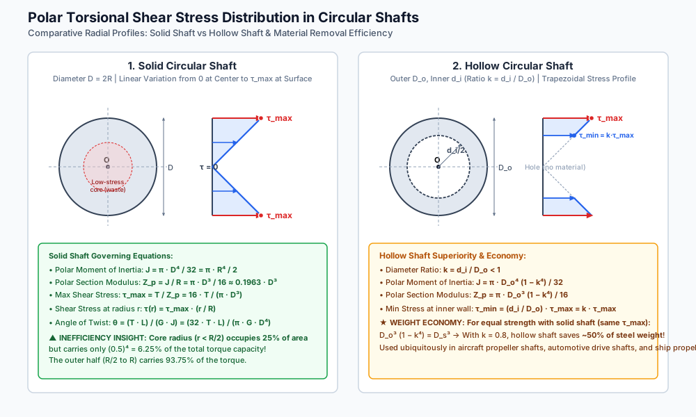
This demonstrates that the shear stress varies strictly linearly with radial distance from the center of the shaft.
3.4 Internal Resisting Torque Equilibrium & Polar Moment of Inertia ()
To establish equilibrium, the sum of moments of all internal tangential shearing stresses across the cross-section must equal the externally applied torque .
Consider a thin elemental concentric annular ring of radius , radial thickness , and elemental cross-sectional area:
- The shear stress acting tangentially on this elemental ring is .
- The internal tangential shear force acting on this elemental ring is:
- Because this shear force acts tangentially at radius from the center of the shaft, its internal resisting torque about the central axis is:
- Integrating over the entire cross-sectional area gives the total internal resisting torque :
The integral is defined mathematically as the Polar Second Moment of Area (Polar Moment of Inertia), denoted by :
Therefore:
For any arbitrary radial coordinate :
3.5 The Universal Torsion Equation
Combining the kinematic-elastic relation and the equilibrium relation yields the Universal Torsion Formula for Circular Shafts:
Where:
- = Applied twisting moment
- = Polar moment of inertia of the cross-section
- = Shear stress at radial distance from the central axis
- = Radial distance of the point from the center
- = Shear modulus of rigidity
- = Angle of twist over length
- = Length of the shaft segment
4. Torsional Section Properties & Parameter Definitions
4.1 Polar Moment of Inertia ()
- Solid Circular Shaft of Diameter (Radius ):
- Hollow Circular Shaft (Outer Diameter , Inner Diameter , ratio ):
4.2 Polar Section Modulus ()
Analogous to the elastic flexural section modulus , the Polar Section Modulus measures the geometric capacity of a shaft to resist torsion for a given allowable shear stress :
The maximum torque that a shaft can safely transmit based on strength criteria is:
- Solid Circular Shaft:
- Hollow Circular Shaft:
4.3 Torsional Rigidity, Stiffness, and Flexibility
- Torsional Rigidity ():
The product of shear modulus and polar moment of inertia . It represents the resistance of the cross-section to angular twisting . - Torsional Stiffness ():
The torque required to produce a unit angle of twist () over the shaft length : - Torsional Flexibility ():
The reciprocal of torsional stiffness; the angle of twist produced by a unit torque:
4.4 Power Transmission by Rotating Shafts
In civil engineering machinery (generators, hydraulic pumps, turbine drive shafts, conveyor drives), shafts rotate at speed and transmit power :
The angular velocity in radians per second:
Power transmitted:
Rearranging for the design twisting moment :
If power is expressed in kilowatts ():
5. State of Stress & Contrasting Material Failure Modes
5.1 Stress Tensor on the Surface of a Shaft in Torsion
Consider an infinitesimal element on the outer cylindrical surface of a shaft subjected to pure torque :
- On the transverse plane (perpendicular to the shaft axis): Normal stress , shear stress .
- On the longitudinal plane (parallel to the shaft axis): By Cauchy's complementary shear law, an identical shear stress acts along the length.
- Normal stress .
This represents a state of Pure Shear.
             Transverse Plane (x-face)
                   +--------+   ^
                   |        |   | tau
             <---  |        |  ---> tau
             tau   |        |
                   +--------+
                        v tau
5.2 Mohr's Circle Analysis & Helical Principal Planes
Plotting this pure shear state on Mohr's circle:
- Center of circle:
- Radius of circle:
- Principal Stresses:
- Principal Plane Orientation:
The principal planes are oriented at to the longitudinal axis of the shaft.
                     45° Helical Plane
                        /  ^  /
                       /  /  /  sigma_1 = +tau (Tension)
                      /  /  /
                     /  v  /
5.3 Contrasting Failure Modes: Ductile vs. Brittle Materials
The state of pure shear explains the fundamentally different failure patterns observed in practice and frequently tested in competitive examinations:
- Ductile Materials (Mild Steel, Structural Aluminum, Copper):
- Ductile metals are weak in shear but strong in tension.
- Failure occurs when the maximum shear stress reaches the shear yield strength ().
- Failure Surface: Fails along a transverse cross-sectional plane at to the shaft axis by ductile sliding and shear cup-and-cone formation.
- Brittle Materials (Cast Iron, Plain Concrete, Geotechnical Rock Cores, Blackboard Chalk):
- Brittle materials are exceptionally weak in tension (tensile strength is typically only of compressive strength) and fail by tensile cleavage fracture rather than shear slip.
- Because the maximum tensile stress acts perpendicular to planes inclined at , the material fractures along a helical spiral surface.
- Exam Observation: When a stick of classroom chalk is twisted by hand, it invariably breaks along a smooth helical fracture line.
6. SVG Technical Illustrations
Figure 1: Kinematic Deformation of Circular Shafts Under Pure Torsion
The diagram below shows the kinematic deformation of a circular shaft, showing longitudinal line distortion, angle of twist , engineering shear strain , and the principal tensile helical failure mechanism.
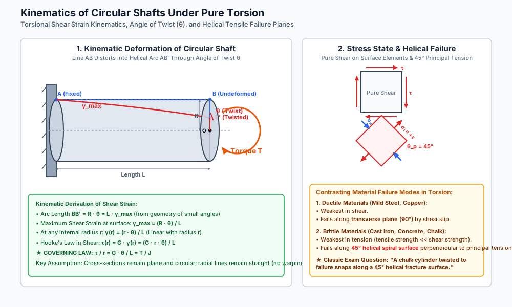
Figure 2: Polar Shear Stress Distribution Across Solid and Hollow Shafts
The diagram below compares the radial shear stress distribution between a solid shaft and a hollow circular shaft, illustrating the extreme material inefficiency of the central core.
7. Python-Recalculated Solved Numerical Examples
Numerical Example 1: Transmission Drive Shaft Sizing (Strength vs. Stiffness)
Problem Statement:
A solid steel drive shaft rotates at and transmits of mechanical power. The shaft is long, and its material has a shear modulus .
The design criteria specify:
- Maximum allowable shear stress .
- Maximum allowable angle of twist over the entire length.
Calculate:
- The required shaft diameter based on strength criteria ().
- The required shaft diameter based on torsional stiffness/rigidity criteria ().
- The governing minimum diameter, select an appropriate commercial size (rounded up to the next integer millimeter), and compute the actual maximum shear stress and actual angle of twist for the selected shaft.
Step-by-Step Solution:
-
Torque Transmitted by the Shaft:
-
Diameter Based on Strength Criteria:
-
Diameter Based on Torsional Stiffness (Angle of Twist):
-
Governing Diameter & Commercial Selection: Comparing the two requirements:
- Strength requires
- Stiffness requires
Select commercial integer diameter: .
-
Actual Performance with :
Numerical Example 2: Stepped Circular Shaft with Intermediate Torques
Problem Statement:
A stepped circular shaft is rigidly clamped at support and free at end .
- Segment : Diameter , Length .
- Segment : Diameter , Length .
- Material: Shear modulus . Torques applied:
- At junction : (clockwise).
- At free end : (clockwise).
Calculate:
- The internal torque in segments and .
- The maximum torsional shear stress in each segment ( and ).
- The angle of twist at junction () and the total angle of twist at free end ().
- The maximum engineering shear strain in segments and .
Step-by-Step Solution:
-
Internal Torques (Free-Body Sections):
- Cutting through segment and considering the free portion to the right:
- Cutting through segment and considering the free portion to the right:
-
Geometric Properties:
- Segment ():
- Segment ():
-
Maximum Shear Stresses:
-
Angles of Twist:
- Twist of segment (which equals angle of twist at since is fixed):
- Twist of segment relative to :
- Total twist at free end :
-
Maximum Shear Strains:
Numerical Example 3: Weight Economy & Performance of Hollow vs. Solid Shafts
Problem Statement:
A solid steel shaft of diameter transmits a torque .
The shaft is to be replaced by a hollow circular shaft of the same material () with outer diameter such that the maximum shear stress in both shafts is identical.
Determine:
- The maximum shear stress in the solid shaft.
- The required internal diameter and the diameter ratio of the hollow shaft.
- The percentage weight reduction achieved by switching to the hollow shaft.
- The ratio of torsional stiffness between the two shafts.
- The angle of twist per meter length for both shafts.
Step-by-Step Solution:
-
Solid Shaft Performance:
-
Required Internal Diameter of Hollow Shaft: For equal strength under the same torque , the polar section moduli must be identical ():
-
Weight Economy Calculation: Cross-sectional area of hollow shaft:
Percentage Weight Savings:
-
Torsional Stiffness Ratio:
-
Angle of Twist Per Meter Length ():
- Solid Shaft:
- Hollow Shaft:
The hollow shaft reduces angular twist by while saving half the metal!
8. Practical Engineering Applications & Structural Design Considerations
- Automotive Propeller & Drive Shafts: Because drive shafts run the entire length of vehicles, weight is critical for fuel efficiency and natural frequency. By using thin hollow steel tubes (), automotive engineers avoid whirling resonance frequencies while saving hundreds of kilograms of unsprung weight.
- Deep Borehole Drilling & Geotechnical Rotary Rigs: Drill strings used in soil sampling, pile boring, and petroleum drilling are hollow steel pipes. The hollow core allows drilling fluid (bentonite slurry) to be pumped down to the cutting bit while providing maximum torsional rigidity against rotational stall.
- Marine Ship Propeller Shafts: Massive commercial ship propeller shafts (often over in diameter and long) are forged hollow. Boring out the central diameter core removes of the weight while reducing torsional strength by only .
- Torque Limiter Shear Pins: In mechanical drives subject to jamming (sludge scrapers in water treatment plants, stone crushers), a sacrificial shear pin of calibrated diameter is inserted. When torque exceeds , the pin shears cleanly at its outer radius, disengaging the motor to prevent catastrophic gearbox destruction.
9. Comparative Analysis & Summary Matrix
| Attribute / Parameter | Solid Circular Shaft () | Hollow Circular Shaft () | Performance Comparison |
|---|---|---|---|
| Cross-Sectional Area () | Hollow has far less area for same diameter | ||
| Polar Moment of Inertia () | Hollow concentrates mass at larger radius | ||
| Polar Section Modulus () | Measure of strength capacity against twisting | ||
| Minimum Shear Stress () | (at center ) | (at inner wall ) | Hollow has no inactive material near zero |
| Maximum Shear Stress () | (at surface) | Peaks at outer surface for both | |
| Stress Distribution Profile | Triangular (apex at center) | Trapezoidal (elevated base) | Hollow profile is much flatter and efficient |
| Angle of Twist () | Inversely proportional to 4th power of diameter | ||
| Weight for Same Strength | Baseline () | (with ) | weight reduction |
10. Key Takeaways & Exam-Oriented Highlights
- The Universal Torsion Equation:
- Kinematic Law: Plane sections remain plane; radial lines remain straight. .
- Linear Shear Stress: varies linearly from at the center to at the outer boundary.
- Polar Modulus: for solid shafts; for hollow shafts.
- Power Transmission Formula:
- Ductile vs. Brittle Torsional Failure:
- Ductile materials fail on the transverse plane (shear failure).
- Brittle materials fail along a helical spiral (tensile cleavage failure perpendicular to principal stress ).
- Design Governing Check: Shafts must be verified for both Strength () and Stiffness (). For long shafts, stiffness almost always governs!
11. Common Traps, Pitfalls & Counter-Intuitive Exam Scenarios
- Trap 1: Forgetting to Convert Degrees to Radians:
Misconception: Directly plugging into .
Correction: in the torsion formula is strictly in radians! You must multiply degrees by before calculating. - Trap 2: Confusing with Flexural Section Modulus :
Misconception: Using instead of .
Correction: Polar moment of inertia is twice the rectangular moment of inertia (). Thus, for a solid circular cross-section! - Trap 3: Mixing Up Power Units:
Misconception: Using in kW directly without multiplying by to get Watts ().
Correction: If is in kW, gives in . Multiply by to get . - Trap 4: Miscalculating Core Torque Capacity:
Misconception: Believing the inner core of radius carries of the torque.
Correction: Torque varies with ! The inner half radius carries only of total torque capacity. - Trap 5: Applying Circular Torsion to Non-Circular Sections:
Misconception: Using for rectangular beams.
Correction: Rectangular bars experience severe warping. Maximum shear stress in a rectangle occurs at the midpoint of the longer edge, not at the corners (where !).
12. Standard Code Provisions & Objective Practice Problems
Reference Code Clauses
- IS 2494: Mechanical transmission shafting design: allowable shear stress under pure torsion is limited to or , whichever is smaller, reduced by a keyway factor of .
- ASME Code for Design of Transmission Shafting: Design based on maximum shear stress theory with shock and fatigue factors and .
- IS 800:2007 (Cl. 8.9): Torsional warping must be accounted for in open thin-walled sections; circular hollow sections (CHS) are recommended for pure torsion.
Objective Practice Problems
Problem 1 (GATE CE)
A solid circular shaft of diameter is subjected to a torque . If the diameter of the shaft is doubled, its torque-carrying capacity for the same allowable shear stress becomes:
- (A) 2 times
- (B) 4 times
- (C) 8 times
- (D) 16 times
Answer: (C)
Solution: . Since , doubling increases capacity by times.
Problem 2 (SSC JE / RRB JE)
A piece of blackboard chalk is twisted to failure. The fracture surface will be:
- (A) A transverse plane perpendicular to the axis
- (B) A longitudinal plane parallel to the axis
- (C) A helical spiral surface inclined at to the axis
- (D) A cup-and-cone irregular surface
Answer: (C)
Solution: Chalk is a brittle material that is much weaker in tension than in shear. Under pure torsion, the maximum principal tensile stress acts on planes inclined at to the longitudinal axis, causing tensile cleavage failure along a helical spiral.
Problem 3 (GATE CE / State AE)
The ratio of polar section modulus to flexural section modulus for a solid circular cross-section is:
- (A)
- (B)
- (C)
- (D)
Answer: (D)
Solution: . Since radius is identical for both, .
Problem 4 (UPSC ESE)
A shaft transmitting power at is subjected to a torque . If the rotational speed is doubled while the transmitted power remains constant, the torque on the shaft:
- (A) Doubles
- (B) Quadruples
- (C) Halves
- (D) Remains unchanged
Answer: (C)
Solution: . If is constant and doubles, is halved.
Problem 5 (GATE CE / ESE)
In a hollow circular shaft of outer diameter and inner diameter , what fraction of the total torsional strength of a solid shaft of diameter is retained?
- (A)
- (B)
- (C)
- (D)
Answer: (C)
Solution: . The ratio of polar section moduli is . Boring out the inner half diameter removes of the weight while retaining of the strength!