Types of Beams, Supports, Loads & Static Determinacy
In this chapter (4 topics)
On this page
- 1. Metadata & Syllabus Mapping
- Official Examination Syllabus Mapping
- 2. Introduction & Physical Mechanics
- Fundamental Structural Functions of Beams:
- 3. Mathematical Formulations & Derivations
- 3.1 Kinematic Boundary Conditions & Support Reactions
- 3.2 Beam Classifications
- 3.3 Static Determinacy & Degree of Indeterminacy (Ds)
- 3.4 Classification and Equivalence of External Loads
- 3.5 Method of Sections for Internal Forces
- 3.6 Standard Sign Conventions for V and M
- ⭐ Memory Aid
- 4. Engineering Assumptions & Limitations
- 5. Technical Diagrams
- Diagram 1: Beam Supports, Kinematic Restraints & Internal Hinge
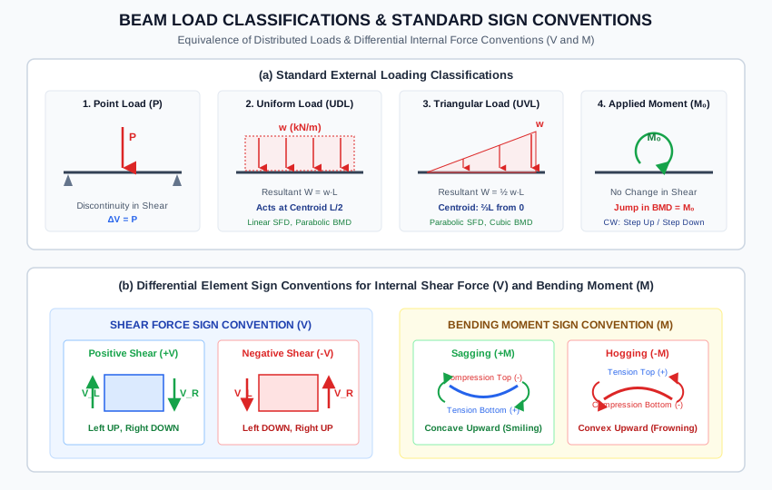
- Diagram 2: Beam Load Classifications & Internal Force Sign Conventions
- 6. Solved Numerical Examples
- Example 1.1: Evaluating Degree of Static Indeterminacy (Ds)
- Example 1.2: Support Reactions for Combined UDL, UVL, and Concentrated Couple
- Example 1.3: Internal Shear and Moment by Method of Sections
- 7. Practical & Field Engineering Applications
- 8. Comparative Analysis
- Summary of Support Types & Boundary Conditions
- Load Classifications & Induced Internal Responses
- 9. Key Engineering Facts & Exam Takeaways
- 10. Common Pitfalls, Traps & Anti-Patterns
- 11. Standards & Code Provisions
- IS 456:2000 (Plain and Reinforced Concrete)
- IS 800:2007 (General Construction in Steel)
- 12. Comprehensive Formula Box & Practice Problems
- Master Formula Summary
- Practice Problems
1. Metadata & Syllabus Mapping
| Attribute | Specification |
|---|---|
| Topic ID | SOM-03-01 |
| Module / Subject | Subject 02: Strength of Materials (notes/strength_of_materials/) |
| Chapter | Chapter 03: Shear Force and Bending Moment Diagrams (03_shear_force_and_bending_moment) |
| Target Examinations | GATE CE, UPSC ESE, SSC JE, RRB JE, State AE, State JE |
| Prerequisites | Engineering Mechanics (Statics & Equilibrium), SOM-01-01 (Stress & Strain Concepts) |
| Primary Code References | IS 456:2000 Clause 22 (Effective Span & Beam Arrangements), IS 800:2007 Section 8 (Flexural Members), IRC:112 |
| Verification Gate | Level 1 through Level 7 Quality Standards |
Official Examination Syllabus Mapping
Website note: this mapping is from the author’s notes. It has not been checked against the official notification for each examination; confirm the current syllabus with the examining body.
- GATE Civil Engineering: Solid Mechanics — Types of beams and supports; static determinacy and degree of indeterminacy; internal hinges; concentrated and distributed loads; sign conventions for shear force and bending moment.
- UPSC ESE (Engineering Services): Paper-I Solid Mechanics & Structural Analysis — Classification of flexural members; boundary conditions and support reactions; equivalent statically determinate systems; method of sections for internal action extraction.
- SSC JE / RRB JE / State AE: Definition of beam; simple, cantilever, overhanging, fixed, and continuous beams; types of supports (roller, hinge, fixed); degrees of freedom; sagging vs hogging bending moment.
2. Introduction & Physical Mechanics
A beam is a structural member designed primarily to support transverse loads acting perpendicular to its longitudinal axis. Unlike axially loaded bars (which develop only longitudinal normal stresses ), transverse loads induce internal Shear Forces () that tend to shear adjacent cross-sections, and internal Bending Moments () that tend to curve and flex the member.
Fundamental Structural Functions of Beams:
- Transfer of Gravity and Lateral Loads: In buildings and bridges, floor slabs transfer dead and live loads to floor beams (joists and girders), which in turn transfer reactions to columns and piers.
- Support Boundary Conditions: Real physical connections (such as elastomeric bridge bearing pads, steel pin connections, and monolithic reinforced concrete beam-column joints) impose specific kinematic displacement restraints, dictating the reactive forces developed at the supports.
- Internal Equilibrium: At every arbitrary internal cut along a beam, the external active loads on one side must be held in static equilibrium by the resultant internal normal force , internal shear force , and internal bending moment developed across the cross-section.
3. Mathematical Formulations & Derivations
3.1 Kinematic Boundary Conditions & Support Reactions
In planar (2D) structural mechanics, a free body has three independent degrees of freedom: horizontal translation (), vertical translation (), and in-plane rotation ().
Supports constrain one or more of these degrees of freedom by generating corresponding reactive forces or moments:
Internal Releases (Special Kinematic Connections):
- Internal Hinge (Moment Release): A physical pin connecting two beam segments. It permits independent rotation of adjacent segments (), transmitting axial force and shear force , but cannot transmit bending moment. An internal hinge provides one additional condition of equilibrium ().
- Internal Shear Release (Guided Slider): Transmits axial force and bending moment , but releases shear (), providing .
3.2 Beam Classifications
Beams are classified according to their support arrangement and structural determinacy:
1. Statically Determinate Beams (Reactions solvable by 3 statics equations alone):
- Cantilever Beam: Fixed rigidly at one end and completely free at the other end ().
- Simply Supported Beam: Supported by a pin/hinge at one end and a roller at the other end ().
- Overhanging Beam: Supported by a pin and a roller, with one or both ends extending freely beyond the supports.
2. Statically Indeterminate Beams (Reactions require compatibility of deformation):
- Propped Cantilever: Fixed at one end and supported by a roller/hinge at the other end ().
- Fixed Beam (Built-in at both ends): Rigidly clamped at both ends ().
- Continuous Beam: Supported on three or more supports across multiple spans ().
3.3 Static Determinacy & Degree of Indeterminacy ()
In a planar beam structure, the global equilibrium equations available from statics are:
Let:
- = Total number of external support reactions.
- = Total number of independent internal equations of condition (releases).
- For each internal hinge connecting 2 members: .
- In general, for an internal hinge connecting members: .
The Degree of Static Indeterminacy () is:
- : The beam is Statically Determinate. All reactions and internal forces can be uniquely determined using the equations of statics.
- : The beam is Statically Indeterminate to degree . Additional deformation compatibility equations (deflection/slope boundary conditions) are mandatory.
- : The structure is unstable (a Mechanism).
3.4 Classification and Equivalence of External Loads
1. Concentrated Point Load ()
- Expressed in or .
- Acts over an infinitesimally small length.
- Causes a sudden finite jump (discontinuity) in the Shear Force Diagram of magnitude .
2. Uniformly Distributed Load (UDL, )
- Expressed in or .
- Constant intensity .
- Equivalent Resultant Force (): Equal to the area under the load diagram:
- Line of Action (Centroid ): Passes through the geometric midpoint of the loaded length:
3. Uniformly Varying Load (UVL, Triangular Load)
- Load intensity varies linearly from at one end to at the other end: .
- Equivalent Resultant Force (): Equal to the area of the load triangle:
- Line of Action (Centroid ):
- Measured from the apex (zero-intensity end):
- Measured from the base (maximum-intensity end):
4. Concentrated Applied Moment / Couple ()
- Expressed in or .
- Produces zero net transverse force ().
- Causes zero change in the Shear Force Diagram, but creates a sudden vertical jump (step change) in the Bending Moment Diagram equal to .
3.5 Method of Sections for Internal Forces
To determine the internal forces at any distance from the left origin, pass an imaginary cutting plane through the section and isolate either the left or right segment.
1. Internal Axial Force ():
The algebraic sum of all active and reactive forces acting parallel to the beam axis to one side of the section:
- Tensile (pulling away from section): Positive ().
- Compressive (pushing into section): Negative ().
2. Internal Shear Force ():
The algebraic sum of all active and reactive forces acting perpendicular to the beam axis to one side of the section:
3. Internal Bending Moment ():
The algebraic sum of the moments of all active and reactive forces and applied couples acting to one side of the section, taken about the centroid of that section:
3.6 Standard Sign Conventions for and
To eliminate ambiguity across structural analysis and design, the universal engineering sign conventions are defined as follows:
========================================================================
SHEAR FORCE CONVENTION (V)
========================================================================
Positive Shear (+V):     Left face UPWARD   / Right face DOWNWARD
Negative Shear (-V):     Left face DOWNWARD / Right face UPWARD

   [Left]      ▲             [Left]      |
               |                         |
            +------+                  +------+
            | Beam |                  | Beam |
            +------+                  +------+
                         ▼               |
              [Right]    |    [Right]    ▼
          Positive (+V)           Negative (-V)

========================================================================
BENDING MOMENT CONVENTION (M)
========================================================================
Positive Moment (+M):    SAGGING  (Concave Upward / Smiling)
                         Top fibers in COMPRESSION (-)
                         Bottom fibers in TENSION   (+)

Negative Moment (-M):    HOGGING  (Convex Upward / Frowning)
                         Top fibers in TENSION     (+)
                         Bottom fibers in COMPRESSION (-)
========================================================================
⭐ Memory Aid
- Sagging (+): "Smiling" beam. Holds water like a cup. Bottom fibers stretch (tension), top fibers compress.
- Hogging (-): "Frowning" beam. Spills water like an umbrella. Top fibers stretch (tension), bottom fibers compress.
4. Engineering Assumptions & Limitations
- Straight Prismatic Member: The beam axis is initially straight, and the cross-section is uniform along the length.
- Small Deflection Theory: Deflections are small compared to beam depth (), ensuring that equilibrium equations can be formulated on the undeformed geometry.
- Plane Sections Remain Plane (Euler-Bernoulli Hypothesis): Cross-sections remain plane and normal to the longitudinal neutral axis after bending.
- Planar Bending: Loads act entirely within a longitudinal plane of symmetry passing through the shear center of the cross-section, ensuring bending occurs without out-of-plane twisting (torsion).
5. Technical Diagrams
Diagram 1: Beam Supports, Kinematic Restraints & Internal Hinge
The technical illustration below details the boundary restraints, released degrees of freedom, and reactive force vectors for Roller, Hinged, Fixed supports, and Internal Hinges.
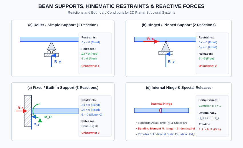
Diagram 2: Beam Load Classifications & Internal Force Sign Conventions
The illustration below details the equivalent resultant formulas for concentrated, uniform, and triangular loads, as well as the standard sign conventions for Shear Force () and Bending Moment ().
6. Solved Numerical Examples
Example 1.1: Evaluating Degree of Static Indeterminacy ()
Determine the external degree of static indeterminacy () and assess the structural stability for the following planar beam configurations:
- Beam A: A propped cantilever beam with a fixed support at , a roller support at , and an internal hinge inserted at midspan.
- Beam B: A continuous beam resting on 4 supports (Hinge at , Rollers at ) with an internal hinge in span .
- Beam C: A beam fixed rigidly at both ends ( and ) with two internal hinges inserted along the span.
Given:
Beam A: Fixed at A (r=3), Roller at B (r=1), Internal hinge at C (ci=1)
Beam B: Hinge at A (r=2), Rollers at B, C, D (r=1 each), Internal hinge in BC (ci=1)
Beam C: Fixed at A (r=3), Fixed at B (r=3), Two internal hinges (ci=2)
Solution:
Using the master formula:
1. Beam A (Propped Cantilever with 1 Internal Hinge):
- Total external reactions: .
- Available statics equations: .
- Internal releases: (Internal hinge at provides ).
Conclusion: Statically Determinate & Stable.
2. Beam B (Continuous Beam over 3 Spans with 1 Internal Hinge):
- Total reactions: .
- Internal releases: .
Conclusion: Statically Indeterminate to the 1st degree.
3. Beam C (Fixed-Fixed Beam with 2 Internal Hinges):
- Total reactions: .
- Internal releases: .
Conclusion: Statically Indeterminate to the 1st degree.
Example 1.2: Support Reactions for Combined UDL, UVL, and Concentrated Couple
A simply supported beam of span is pinned at () and on a roller at (). It is loaded as follows:
- Uniformly distributed load extending over the left half ( to ).
- Linearly varying load (UVL) increasing from at () to at ().
- Concentrated clockwise moment applied at point ().
Determine:
- The equivalent resultant forces and centroidal positions of the distributed loads.
- The vertical support reactions and .
- Verify global moment equilibrium about support .
Given:
Span L = 8.0 m
UDL on [0, 4.0 m]: w1 = 15.0 kN/m
UVL on [4.0, 8.0 m]: apex at x = 4.0 m, base w2 = 30.0 kN/m at x = 8.0 m
Applied Couple at x = 4.0 m: M0 = 40.0 kNm (Clockwise)
Solution:
Step 1: Equivalent Load Resultants and Centroids
-
UDL over segment ():
Centroid from support :
-
UVL over segment ():
Centroid of triangle is located at of its base length from apex :
Centroid from support :
Step 2: Calculate Reactions via Static Equilibrium
-
Taking moments about support (, clockwise positive):
-
Vertical equilibrium ():
-
Horizontal equilibrium ():
Step 3: Verification of Equilibrium about Support
- Clockwise moments about :
- Counterclockwise moments about :
- Distance of UDL centroid from : .
- Distance of UVL centroid from : .
Example 1.3: Internal Shear and Moment by Method of Sections
For the beam analyzed in Example 1.2 (), calculate the internal shear force and bending moment at the following cross-sections:
- Section 1 at (midpoint of UDL).
- Section 2 at (immediately to the left of point ).
- Section 3 at (immediately to the right of point ).
- Section 4 at (midway through the UVL span). Verify Section 4 using both left and right free-body cuts.
Solution:
1. Section 1 at (Considering Left Segment ):
- Shear Force:
- Bending Moment:
2. Section 2 at (Just to the Left of ):
- Shear Force:
- Bending Moment:
3. Section 3 at (Just to the Right of ):
- Shear Force: Because the applied moment has zero transverse force:
- Bending Moment: The clockwise concentrated couple acts in the sagging sense on the left segment:
4. Section 4 at :
-
From Left Segment (): At (which is past ), the UVL intensity is:
The area of this triangular UVL segment from to is:
Its centroid is at from , which is from the cut section.
- Shear Force:
- Bending Moment:
-
Verification from Right Segment (, length ): Between and , the load is a trapezoid:
- Base rectangle: height , length at from section.
- Triangle: apex at , height , length at from section.
- Right support reaction: at from section.
- Shear Force (Downward on right face is positive):
- Bending Moment (Sagging about cut: rotates clockwise, loads rotate counterclockwise):
7. Practical & Field Engineering Applications
-
Bridge Bearings & Thermal Expansion (IRC:112):
Bridge superstructures cannot be fixed rigidly at all piers. Standard design utilizes a fixed hinge bearing at one pier/abutment (restraining horizontal longitudinal forces from braking and seismic thrust) and elastomeric or PTFE sliding roller bearings at all intermediate piers to allow unconstrained thermal expansion () without generating catastrophic axial forces. -
Gerber Beams in Long-Span Bridges:
Invented by Heinrich Gerber (1866), a continuous beam is made statically determinate by inserting internal hinges at inflection points. This allows the beam to settle differential foundations safely without inducing secondary bending moments. -
Building Transfer Girders:
When architectural layouts require column-free lobbies at the ground floor, upper columns terminate on massive transfer girders. These girders experience enormous concentrated point loads, producing severe shear forces that govern web thickness and stirrup spacing under IS 456:2000. -
Tower Crane Jibs:
The forward boom of a tower crane acts as a cantilever beam subjected to a movable concentrated load (the hoist trolley) and an applied end moment from guy cables.
8. Comparative Analysis
Summary of Support Types & Boundary Conditions
| Support Type | Reaction Forces | Reaction Moments | Total Unknowns () | Restrained DOF | Released DOF | Physical Analogue |
|---|---|---|---|---|---|---|
| Roller | Bridge rocker / elastomeric pad | |||||
| Hinged / Pinned | Steel gusset pin connection | |||||
| Fixed / Built-In | None | Monolithic RC column-beam joint | ||||
| Internal Hinge | Internal | Condition | Displacements matched | Slope relative | Pin in Gerber girder |
Load Classifications & Induced Internal Responses
| Load Type | Mathematical Form | Resultant Force | Centroid | Shear Force Curve | Bending Moment Curve |
|---|---|---|---|---|---|
| Concentrated Load () | Dirac delta | At point of application | Step discontinuity () | Slope change () | |
| UDL () | Constant | Linear (1st degree polynomial) | Parabolic (2nd degree polynomial) | ||
| UVL (Triangular ) | Linear | from apex | Parabolic (2nd degree) | Cubic (3rd degree polynomial) | |
| Concentrated Couple () | Moment derivative | At point of application | Continuous (No change in ) | Step jump () |
9. Key Engineering Facts & Exam Takeaways
- Internal Hinge Always Yields : An internal hinge cannot transmit bending moment. Bending moment at the hinge center is always identically zero.
- Applied Couple Does Not Affect Shear: A concentrated applied moment alters support reactions, but between sections it produces zero change in internal shear force. It produces a discrete vertical step jump in the BMD.
- Point Load Produces Shear Jump: A concentrated transverse force produces an instantaneous vertical step in the SFD of magnitude .
- Static Determinacy Test: A planar beam is statically determinate if and only if and the structure is geometrically stable (supports are not parallel or concurrent).
- Universal Sagging/Hogging Rule: Always evaluate bending moments as sagging () or hogging (), regardless of whether you calculate from the left or right side!
10. Common Pitfalls, Traps & Anti-Patterns
- Trap 1 (Centroid of Triangular Load): For a triangular load (UVL), confusing the and distance rules. The centroid is always from the vertical base (heavy end) and from the apex (sharp end).
- Trap 2 (Sign Reversal when Working from Right): Forgetting that when analyzing a section from the right side, upward forces cause negative shear and downward forces cause positive shear.
- Trap 3 (Treating Internal Hinge as a Support): An internal hinge is an internal release, not an external support reaction! It does not provide an external reaction force ; it provides a mathematical condition .
- Trap 4 (Ignoring in Reaction Calculations): When calculating support reactions, neglecting the concentrated couple because it has no vertical force. enters the moment equilibrium equation directly!
- Trap 5 (Confusing Cantilever and Propped Cantilever Determinacy): A cantilever is statically determinate (), whereas a propped cantilever is indeterminate to the first degree ().
11. Standards & Code Provisions
IS 456:2000 (Plain and Reinforced Concrete)
- Clause 22.2 (Effective Span):
- For simply supported beams: , where is clear span, is effective depth, and is support width.
- For continuous beams: If support width is less than , effective span is taken as the center-to-center of supports.
- Clause 22.4 (Critical Sections for Moments and Shears):
Specifies rules for redistributing bending moments in continuous beams up to to optimize ductile reinforcing.
IS 800:2007 (General Construction in Steel)
- Clause 8.1 & Clause 8.2 (Design of Flexural Members):
Requires verifying lateral-torsional buckling of beams between supported points and checking cross-section classification (Plastic, Compact, Semi-compact).
12. Comprehensive Formula Box & Practice Problems
Master Formula Summary
Practice Problems
-
Problem 1 (GATE CE Objective):
A propped cantilever beam of span is fixed at and supported on a roller at . An internal hinge is provided at a distance from . The degree of static indeterminacy of the beam is:
Answer: (Statically Determinate)
Explanation: . for the internal hinge. . -
Problem 2 (SSC JE Objective):
A sagging bending moment in a beam induces:
Answer: Tensile stress in the bottom fibers and compressive stress in the top fibers.
Explanation: Sagging produces a concave-upward curvature, stretching bottom fibers (tension) and shortening top fibers (compression). -
Problem 3 (GATE CE Numerical):
A simply supported beam of span carries a triangular load varying from at support to at support . The vertical reaction at support is:
Answer:
Explanation: Total load . Centroid from is .
Taking moment about : . -
Problem 4 (UPSC ESE Style):
At a section where a clockwise concentrated couple is applied on a simply supported beam:
Answer: The shear force diagram remains continuous, while the bending moment diagram undergoes an abrupt jump of magnitude .
Explanation: A pure couple exerts zero transverse force; hence does not jump, while exhibits an instantaneous step change of . -
Problem 5 (State AE Objective):
The number of internal equations of condition provided by an internal hinge connecting structural members is:
Answer:
Explanation: When members meet at an internal hinge, independent relative rotations are permitted, providing moment release equations.