Overhanging Beams and Points of Contraflexure
In this chapter (4 topics)
On this page
- 1. Topic Metadata
- 2. Physical Mechanics & Theoretical Foundation
- 2.1 Mechanics of Overhangs & Moment Reversal
- 3. Mathematical Derivations & Governing Equations
- 3.1 Symmetrical Double Overhanging Beam under Uniformly Distributed Load w
- 3.2 Determination of Points of Contraflexure
- 3.3 Optimum Minimax Overhang Ratio (Equal Sagging and Hogging Moments)
- 3.4 Single Overhanging Beam Mechanics
- 4. Engineering Assumptions & Validity Limits
- 5. SVG Technical Illustrations & Diagrammatic Analysis
- Figure 1: Double Overhanging Beam SFD, BMD & Contraflexure
- Figure 2: Optimum Overhang Ratio Analysis Curves
- 6. Solved Numerical Examples (Python-Verified)
- Example 1: Symmetrical Double Overhanging Beam — Precise Contraflexure Locations
- Example 2: Industrial Pipe Bridge — Minimax Optimization for Equal Sagging and Hogging Moments
- Example 3: Single Overhanging Beam with End Point Load and Span UDL
- 7. Engineering Applications & Real-World Case Studies
- 8. Comparative Analysis & Summary Matrix
- 9. Key Takeaways & Exam-Oriented Mnemonics
- 10. Common Pitfalls, Traps & Misconceptions
- 11. Standard Specifications & Code Provisions
- 12. Comprehensive Formula Box & Practice Problems
- Governing Formula Summary
- Practice Problems
1. Topic Metadata
| Field | Detail |
|---|---|
| Topic Identifier | SOM-03-04 |
| Subject | Strength of Materials / Solid Mechanics |
| Chapter | Shear Force and Bending Moment Diagrams (SFD & BMD) |
| Difficulty Level | Intermediate to Advanced |
| Target Examinations | GATE CE, UPSC ESE, SSC JE, State AE/JE, RRB JE |
| Primary Prerequisites | Static Equilibrium (), Differential Relations (), SFD/BMD for Cantilevers & Simply Supported Beams |
| Benchmark Formulas | Double Overhang Minimax: ; Single Overhang Minimax: |
| Authoritative Code References | IS 456:2000, IS 800:2007, IRC:112-2020 |
2. Physical Mechanics & Theoretical Foundation
An overhanging beam is a statically determinate structure that combines the structural behaviors of both simply supported beams and cantilevers. It is supported by a hinge and roller placed at internal locations, such that one or both ends extend freely beyond the supports.
2.1 Mechanics of Overhangs & Moment Reversal
- Cantilever Action over Supports (Hogging): The portion of the beam extending past a support behaves as a cantilever. Gravity loads acting on this cantilever overhang produce an internal bending moment that bends the beam convex upward over the support. This induces tensile stresses in the top fibers and compressive stresses in the bottom fibers, which constitutes a hogging (negative) bending moment.
- Span Action between Supports (Sagging): The internal span between the two supports behaves analogously to a simply supported beam. However, instead of resting on zero-moment pin supports, the internal span is subjected to relieving negative end moments ( and ) exerted by the overhangs. This counteracts the central gravity load, lifting the middle span upward and substantially reducing the midspan sagging moment.
- The Point of Contraflexure (Point of Inflection):
Because the bending moment is negative (hogging) over the support and transitions to positive (sagging) in the central span, the bending moment must cross the zero baseline ().
- A point of contraflexure is defined mathematically as a point along the beam axis where:
- Physical Meaning: At the point of contraflexure, the beam's elastic curvature reverses (transitioning from convex up to concave up). Consequently, normal bending stresses across the entire cross-section are identically zero:
- In reinforced concrete design, the point of contraflexure dictates where longitudinal reinforcement must transition from the top face (resisting hogging) to the bottom face (resisting sagging).
3. Mathematical Derivations & Governing Equations
3.1 Symmetrical Double Overhanging Beam under Uniformly Distributed Load
Consider a beam of total length supported symmetrically at and , separated by an internal span , with overhangs of length at each end (, , ).
        C (Free)          A (Support)                B (Support)          D (Free)
        |←───── a ──────→|←───────────── L ────────────→|←───── a ──────→|
        =================▲==============================▲=================
1. Support Reactions
Total downward load on the beam:
By complete loading and structural symmetry:
2. Hogging Moment at Supports ( at Support )
Evaluating the cantilever overhang from the left free end :
3. Bending Moment in Internal Span ( from Support )
At distance from support :
Notice that the bending moment expression is the superposition of:
- The standard simply supported moment:
- The constant hogging baseline shift caused by the overhangs:
4. Maximum Sagging Moment at Midspan ()
Setting :
3.2 Determination of Points of Contraflexure
Points of contraflexure occur where the bending moment vanishes within the internal span ():
Dividing through by (assuming ):
This is a standard quadratic equation in . Applying the quadratic formula:
Geometric & Physical Interpretation of the Discriminant :
- Case 1: (): The discriminant is strictly positive, yielding two real, distinct points of contraflexure symmetrically spaced at equal distances on either side of the midspan:
- Case 2: (): The two points merge into a single tangent point at the exact midspan: At this point, . The bending moment curve touches the baseline without crossing it.
- Case 3: (): The roots are imaginary; the bending moment is strictly negative (hogging) throughout the entire beam. There are zero points of contraflexure.
3.3 Optimum Minimax Overhang Ratio (Equal Sagging and Hogging Moments)
To minimize the required cross-sectional size of a prismatic beam of given material strength, the absolute maximum design moment must be minimized.
Because increases monotonically with , and decreases monotonically with , the optimum minimax condition occurs when the two peak moments are exactly equal in magnitude:
Peak Design Moment at Optimum Ratio:
Key Comparative Takeaway: A simply supported beam of span without overhangs has . By introducing optimum overhangs , the peak moment is reduced to —an exact reduction in flexural stress and required section modulus !
Optimum Ratio in Terms of Total Beam Length :
3.4 Single Overhanging Beam Mechanics
Consider a beam supported at and (span ) with a single overhang of length past support to tip , carrying a full-length UDL .
       A (Support)                    B (Support)          C (Free)
       |←───────────── L ────────────→|←───── a ──────→|
       ▲==============================▲=================
- Reactions: Taking moments about :
- Hogging Moment at Support :
- Maximum Sagging Moment in Span : Shear force vanishes at :
- Optimum Single Overhang Ratio for Equal Moments: Equating :
4. Engineering Assumptions & Validity Limits
- Planar Small-Deflection Behavior: Classical Euler-Bernoulli assumptions apply; lateral-torsional buckling of the overhang compression flange is prevented by adequate lateral bracing.
- Unyielding Rigid Supports: Supports and do not undergo differential settlement. (In indeterminate continuous beams, settlement drastically alters moments, but for determinate overhanging beams, static reactions and moments are independent of support settlement).
- Continuous Uniform Self-Weight: Load is uniformly distributed per unit horizontal length.
- Prismatic Section Geometry: Cross-sectional properties and are uniform throughout the length.
5. SVG Technical Illustrations & Diagrammatic Analysis
Figure 1: Double Overhanging Beam SFD, BMD & Contraflexure
The diagram below illustrates the complete structural behavior of a double overhanging beam under full UDL, showing the deflected S-shape, the linear shear force profile with support jumps, and the parabolic bending moment diagram with the two symmetrical points of contraflexure.
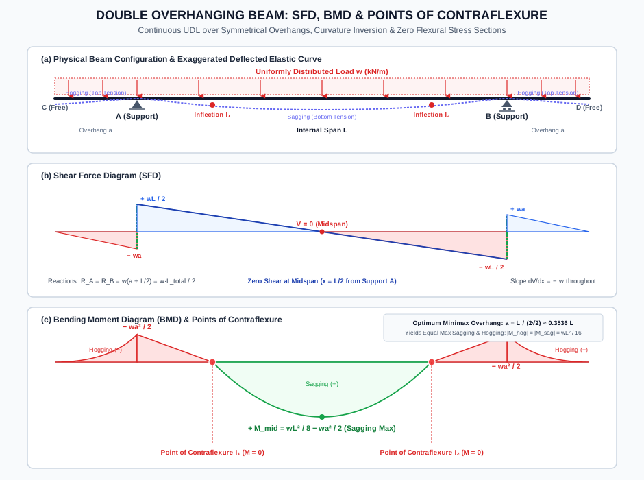
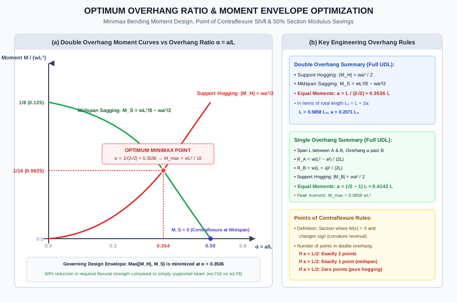
Figure 2: Optimum Overhang Ratio Analysis Curves
The diagram below plots the variation of midspan sagging moment and support hogging moment against the overhang ratio , highlighting the minimax intersection at and the midspan contraflexure threshold at .
6. Solved Numerical Examples (Python-Verified)
Example 1: Symmetrical Double Overhanging Beam — Precise Contraflexure Locations
Problem Statement: A timber bridge beam of total length is supported on two piers and placed apart (), with symmetrical overhangs at each end. The beam carries a uniform dead plus live load of over its entire length.
- Determine the pier reactions and .
- Calculate the bending moments at the supports and at the center of the span.
- Determine the exact coordinates of the points of contraflexure measured from support and from the left tip .
- Sketch the qualitative deflected profile of the beam.
Solution:
Step 1: Pier Support Reactions: Total downward load on the beam:
By symmetry:
Step 2: Critical Bending Moments:
- Bending Moment at Supports and : Taking moments of the cantilever overhang:
- Bending Moment at Midspan ( from ): Using the general formula: (Alternative check from section cut: , verified!)
Step 3: Determination of Points of Contraflexure: Set in the central span ( from support ):
Dividing through by :
Applying the quadratic formula:
Evaluating numerical roots:
Measured from the left free end ():
Example 2: Industrial Pipe Bridge — Minimax Optimization for Equal Sagging and Hogging Moments
Problem Statement: An industrial flume pipe of total length weighs when full of water. It is to be mounted on two symmetrical ground saddles spaced distance apart, with overhangs on each side ().
- Calculate the optimum support spacing and overhang that minimizes the required pipe wall thickness by equalizing the absolute maximum sagging and hogging moments.
- Determine this minimized peak design moment .
- Calculate the percentage moment reduction achieved compared to supporting the flume simply at its two ends ().
Solution:
Step 1: Optimum Dimension Evaluation: For equal maximum sagging and hogging bending moments under full UDL:
Substitute into the total length relation :
Given :
(Verification of ratio: , exact match!)
Step 2: Peak Design Bending Moment:
Thus, the peak design moment is:
Step 3: Comparison with End-Supported Beam (): If the pipe were supported at its extreme ends:
Percentage reduction in design moment:
Practical Impact: Optimizing the saddle locations reduces the peak flexural demand by , enabling a vastly lighter, thinner-walled, and more cost-effective pipe section!
Example 3: Single Overhanging Beam with End Point Load and Span UDL
Problem Statement: A beam has support at , support at , and an overhang of length extending to free tip (). It is loaded by:
- A continuous UDL over the entire length.
- A downward concentrated point load at the free tip .
Determine:
- Support reactions and .
- The peak hogging moment at support .
- The location and magnitude of the maximum sagging moment in span .
- The exact location of the point of contraflexure.
Solution:
Step 1: Global Equilibrium & Support Reactions: Total downward load on beam:
Taking moments about support (, clockwise positive):
From vertical equilibrium ():
Step 2: Peak Hogging Moment at Support (): Evaluating the overhang segment from the right face at :
Step 3: Maximum Sagging Moment in Span : Shear force in span ():
Setting :
Maximum sagging moment at :
Step 4: Point of Contraflexure in Span : Setting :
Roots are (support , simple pin) and:
Between and , (sagging); between and , (hogging). Therefore, is the true point of contraflexure!
7. Engineering Applications & Real-World Case Studies
- Gerber Girders & Cantilever Bridges (e.g., Forth Bridge, Howrah Bridge): Long-span cantilever bridges utilize double overhanging anchor arms that project toward the navigation channel, with internal hinges inserted precisely near the points of contraflexure. Placing physical hinges where bending moments naturally vanish minimizes the required shear pin diameter and avoids high rotational restraints.
- Reinforced Concrete Rebar Detailing & Splices (IS 456:2000 Cl. 26.2.5): In overhanging floor slabs and balcony projections, the top tensile steel must be securely anchored beyond the point of contraflexure by a minimum development length plus or . Rebar splices are strictly prohibited near the support (where hogging moment is maximal); lap splices must be shifted toward the point of contraflexure where flexural stresses are minimal.
- Tower Crane Design & Counterweights: The counterweight jib of a construction tower crane acts as a single overhang that offsets the working jib load, deliberately producing a negative balancing moment over the tower mast to minimize flexural stresses in the slewing ring.
- Highway Bridge Continuous Post-Tensioned Voided Slabs (IRC:112-2020): Over intermediate bridge piers, severe hogging moments occur. Post-tensioned ducts are draped upwards to the top flange over the piers and draped downwards to the bottom flange at midspan, crossing the centroidal neutral axis precisely at the calculated points of contraflexure.
8. Comparative Analysis & Summary Matrix
| Parameter / Feature | Simply Supported Beam (No Overhang) | Symmetrical Double Overhang () | Single Overhang () |
|---|---|---|---|
| Support Locations | Extreme ends () | Internal piers with overhangs | One end support, one internal pier |
| Max Hogging Moment | (No hogging) | ||
| Max Sagging Moment | |||
| Governing Design Moment | ( reduction) | ( reduction) | |
| Points of Contraflexure | (No curvature reversal) | Exactly points | Exactly point |
| Rebar Layout (RC) | Bottom rebars only | Top rebars over piers + bottom at midspan | Top rebars over pier + bottom at midspan |
9. Key Takeaways & Exam-Oriented Mnemonics
- The Double Overhang Minimax Golden Number: :
- Memory aid: .
- Results in equal peak moments: .
- The Single Overhang Golden Number: :
- Memory aid: .
- The Midspan Zero Sagging Threshold: :
- If : 2 points of contraflexure exist.
- If : exactly 1 point of contraflexure (at midspan).
- If : 0 points of contraflexure (pure hogging throughout).
- Point of Contraflexure Definition: It is NOT merely (which occurs at any simple end support); it must involve an actual change of sign across the section (curvature reversal).
10. Common Pitfalls, Traps & Misconceptions
[!WARNING] Pitfall 1: Confusing Overhang Length with Total Beam Length In competitive exams, questions often ask for the ratio of overhang to the distance between supports (), whereas other questions ask for the ratio of overhang to the total beam length (). Always check whether the denominator is the internal span or the total span !
[!CAUTION] Pitfall 2: Claiming that Points of Contraflexure Occur in Simply Supported Beams Simply supported beams have at their end supports, but these are boundary conditions, not points of contraflexure. A point of contraflexure requires curvature reversal within the beam span.
[!NOTE] Pitfall 3: Uplift Reactions under Heavy Overhang Loads In a single overhanging beam, if the overhang load is excessively heavy (), the far support reaction can become negative (downward), meaning the beam lifts off its support unless physically tied down!
11. Standard Specifications & Code Provisions
| Standard | Clause / Section | Engineering Requirement |
|---|---|---|
| IS 456:2000 | Cl. 26.2.3.3 | Reinforcement curtailment at points of contraflexure: positive moment tension reinforcement must extend past the theoretical point of contraflexure by not less than or , whichever is greater. |
| IS 456:2000 | Cl. 26.2.1.1 | Anchorage of negative flexural reinforcement over supports: bars must be anchored into the span past the point of contraflexure by development length . |
| IS 800:2007 | Cl. 8.2.2 | Lateral-torsional buckling in cantilever overhangs: because the bottom flange is in compression under hogging, lateral support must be provided to the bottom flange near the support. |
| IRC:112-2020 | Cl. 9.4 | Tendon layout inflection: prestressing duct curvature inflection points should align with points of contraflexure under permanent dead loads to maximize tendon eccentricity efficiency. |
12. Comprehensive Formula Box & Practice Problems
Governing Formula Summary
Practice Problems
-
(GATE CE Pattern) A beam of span between supports has equal overhangs of length at each end. It carries a UDL over its entire length. For what value of will the bending moment at midspan be zero?
- Answer: .
-
(UPSC ESE Pattern) A symmetrical double overhanging beam has total length . To minimize the maximum bending moment under a uniform load over the entire length, what should be the distance between the two supports?
- Answer: .
-
(State AE Pattern) At a point of contraflexure in a loaded beam, which of the following quantities is zero?
- (A) Shear force
- (B) Bending moment
- (C) Deflection
- (D) Slope
- Answer: (B) Bending moment.