SOM-06-02 Chapter 06 · Torsion of Shafts

Solid vs Hollow Circular Shafts, Shaft Couplings & Keys

In this chapter (3 topics)
On this page
  1. 1. Topic Metadata & Scope
  2. 2. Physical Mechanics & Theoretical Foundation
  3. 2.1 Why Hollow Shafts Are Vastly Superior in Torsion
  4. 2.2 Definition of the Diameter Ratio (k)
  5. 3. Mathematical Derivations: Solid vs Hollow Shafts
  6. 3.1 Case A: Equal Strength Criteria (Same Torque T and Same Maximum Shear Stress τmax)
  7. 3.2 Case B: Equal Weight Criteria (Same Material, Same Cross-Sectional Area Ah = As)
  8. 3.3 Case C: Same Outer Diameter (Do = Ds) with a Concentric Bore
  9. 4. Shafts in Series & Statically Indeterminate Torsion
  10. 4.1 Shafts in Series
  11. 4.2 Statically Indeterminate Shaft Fixed at Both Ends
  12. 5. Shafts in Parallel & Composite Concentric Shafts
  13. 5.1 Shafts in Parallel (Concentric / Flitched Shafts)
  14. 6. Mechanical Connections: Keys & Rigid Flange Shaft Couplings
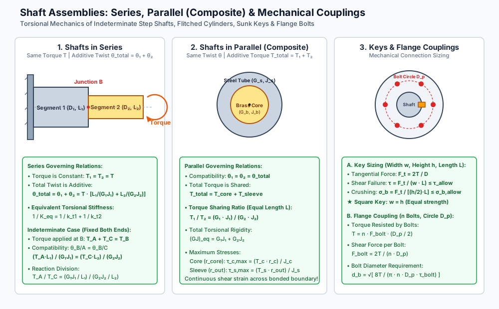
  15. 6.1 Sunk Rectangular & Square Keys
  16. 6.2 Rigid Flange Shaft Couplings
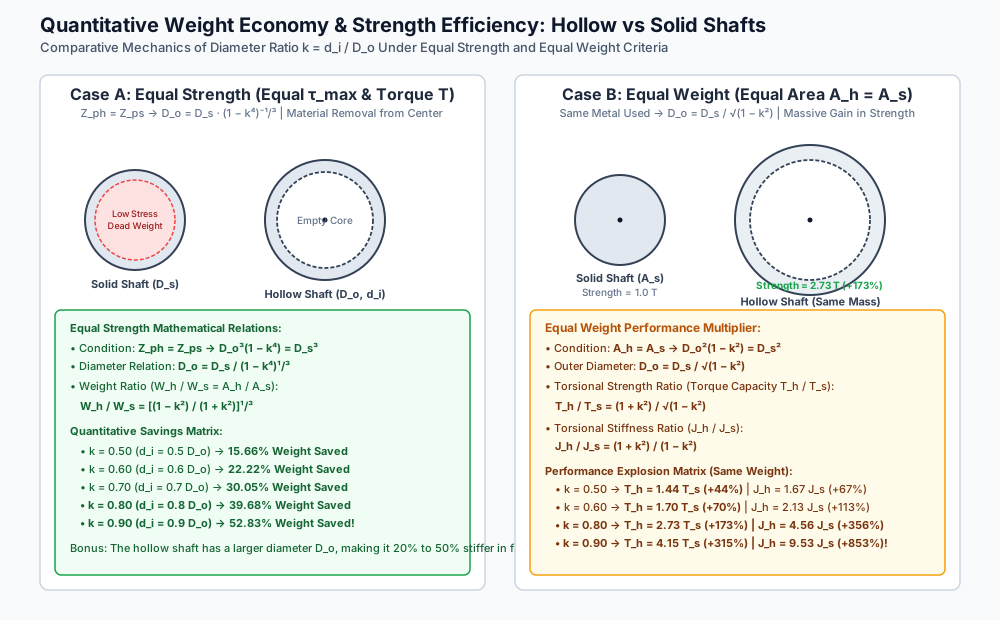
  17. 7. SVG Technical Illustrations
  18. Figure 1: Quantitative Weight Economy & Strength Efficiency: Hollow vs Solid Shafts
  19. Figure 2: Shaft Assemblies: Series, Parallel (Composite) & Mechanical Couplings
  20. 8. Python-Recalculated Solved Numerical Examples
  21. Numerical Example 1: Composite Concentric Shaft (Shafts in Parallel)
  22. Numerical Example 2: Statically Indeterminate Stepped Shaft Fixed at Both Ends
  23. Numerical Example 3: Sunk Key & Flange Coupling Design
  24. 9. Practical Engineering Applications & Structural Design Considerations
  25. 10. Comparative Analysis & Summary Matrix
  26. 11. Key Takeaways & Exam-Oriented Highlights
  27. 12. Common Traps, Pitfalls & Counter-Intuitive Exam Scenarios
  28. 13. Standard Code Provisions & Objective Practice Problems
  29. Reference Code Clauses
  30. Objective Practice Problems

1. Topic Metadata & Scope

Attribute Specification
Topic ID SOM-06-02
Chapter Chapter 06: Torsion of Circular Shafts (06_torsion_of_shafts)
Subject Strength of Materials (Solid Mechanics)
Target Examinations GATE CE, UPSC ESE, SSC JE, State AE, RRB JE
Prerequisites SOM-06-01 (Pure Torsion Formula & Kinematics of Circular Shafts), SOM-01-05 (Statically Indeterminate Systems), SOM-04-03 (Composite / Flitched Beams Analog)
Authoritative Reference Codes IS 2048:1983 (Parallel Keys and Keyways), IS 3688:1990 (Dimensions for Shaft Couplings), IS 2494 (Transmission Shafting)
Key Terminology Diameter ratio (k=di/Dok = d_i/D_o), weight economy, strength efficiency, shafts in series, shafts in parallel, statically indeterminate torsion, composite concentric shaft, rectangular and square sunk keys, shear failure vs crushing failure of keys, rigid flange coupling, pitch circle diameter (DpD_p)

2. Physical Mechanics & Theoretical Foundation

2.1 Why Hollow Shafts Are Vastly Superior in Torsion

In any circular shaft subjected to pure torsion, the shear stress varies strictly linearly from zero at the longitudinal axis (r=0r = 0) to a maximum value τmax⁡\tau_{\max} at the outermost cylindrical surface (r=Rr = R).

The contribution of any elemental annular ring to the total torque capacity is:

dT=r⋅dF=r⋅(τ(r) dA)∝r2 dA∝r3 drdT = r \cdot dF = r \cdot (\tau(r) \, dA) \propto r^2 \, dA \propto r^3 \, dr

Consequently, the torque-resisting capacity of any concentric layer is proportional to the fourth power of its radius (r4r^4):

  • The Core Inefficiency: The central cylindrical core of a solid shaft (where r≤R/2r \le R/2) occupies: Area Fraction=(R/2R)2=14=25% of the total cross-sectional area (and metal weight)\text{Area Fraction} = \left(\frac{R/2}{R}\right)^2 = \frac{1}{4} = 25\% \text{ of the total cross-sectional area (and metal weight)} However, because the polar moment of inertia varies with r4r^4: Torque Capacity Fraction=(R/2R)4=116=6.25% of the total torque capacity!\text{Torque Capacity Fraction} = \left(\frac{R/2}{R}\right)^4 = \frac{1}{16} = 6.25\% \text{ of the total torque capacity!}
  • Therefore, removing this under-stressed central core removes 25%25\% of the dead weight while sacrificing only 6.25%6.25\% of the torsional strength!

2.2 Definition of the Diameter Ratio (kk)

For a hollow circular shaft with outer diameter DoD_o and inner diameter did_i:

k=diDo(0<k<1)k = \frac{d_i}{D_o} \quad (0 < k < 1)

As k→1k \to 1, the shaft approaches an ultra-thin circular tube, where all material is concentrated at maximum radius and subjected to nearly uniform maximum shear stress (τmin⁡=k⋅τmax⁡≈τmax⁡\tau_{\min} = k \cdot \tau_{\max} \approx \tau_{\max}).


3. Mathematical Derivations: Solid vs Hollow Shafts

3.1 Case A: Equal Strength Criteria (Same Torque TT and Same Maximum Shear Stress τmax⁡\tau_{\max})

Consider a solid shaft of diameter DsD_s and a hollow shaft of outer diameter DoD_o and inner diameter di=kDod_i = k D_o, made of identical material and having identical length LL.

For both shafts to have the exact same maximum shear stress τmax⁡\tau_{\max} under the same applied torque TT:

Zph=ZpsZ_{ph} = Z_{ps} πDo3(1−k4)16=πDs316  ⟹  Do3(1−k4)=Ds3\frac{\pi D_o^3 (1 - k^4)}{16} = \frac{\pi D_s^3}{16} \implies D_o^3 (1 - k^4) = D_s^3 Do=Ds(1−k4)1/3=Ds(1−k4)−1/3D_o = \frac{D_s}{(1 - k^4)^{1/3}} = D_s (1 - k^4)^{-1/3}

The weight ratio of the two shafts (since lengths and densities are identical) is equal to their cross-sectional area ratio:

WhWs=AhAs=π4(Do2−di2)π4Ds2=Do2(1−k2)Ds2\frac{W_h}{W_s} = \frac{A_h}{A_s} = \frac{\frac{\pi}{4}(D_o^2 - d_i^2)}{\frac{\pi}{4} D_s^2} = \frac{D_o^2 (1 - k^2)}{D_s^2}

Substituting Do/Ds=(1−k4)−1/3D_o / D_s = (1 - k^4)^{-1/3}:

WhWs=[(1−k4)−1/3]2(1−k2)=1−k2(1−k4)2/3=1−k2[(1−k2)(1+k2)]2/3=(1−k2)1/3(1+k2)2/3=(1−k21+k2)1/3\frac{W_h}{W_s} = \left[(1 - k^4)^{-1/3}\right]^2 (1 - k^2) = \frac{1 - k^2}{(1 - k^4)^{2/3}} = \frac{1 - k^2}{[(1 - k^2)(1 + k^2)]^{2/3}} = \frac{(1 - k^2)^{1/3}}{(1 + k^2)^{2/3}} = \left(\frac{1 - k^2}{1 + k^2}\right)^{1/3}

The Percentage Weight Saving is:

% Weight Saving=[1−(1−k21+k2)1/3]×100%\% \text{ Weight Saving} = \left[1 - \left(\frac{1 - k^2}{1 + k^2}\right)^{1/3}\right] \times 100\%
Diameter Ratio (k=di/Dok = d_i/D_o) Outer Diameter Expansion (Do/DsD_o/D_s) Weight Ratio (Wh/WsW_h/W_s) Percentage Steel Weight Saved
0.400.40 1.0091.009 0.8980.898 10.20%10.20\%
0.500.50 1.0221.022 0.8430.843 15.66%15.66\%
0.600.60 1.0501.050 0.7780.778 22.22%22.22\%
0.700.70 1.1001.100 0.7000.700 30.05%30.05\%
0.800.80 1.1921.192 0.6030.603 39.68%39.68\% (~40%)
0.850.85 1.2721.272 0.5440.544 45.59%45.59\%
0.900.90 1.4111.411 0.4720.472 52.83%52.83\% (>50%)

[!TIP] By choosing k=0.80k = 0.80, an engineer saves 40%40\% of the steel weight while expanding the outer diameter by only 19.2%19.2\%. At k=0.90k = 0.90, over half the weight is saved!


3.2 Case B: Equal Weight Criteria (Same Material, Same Cross-Sectional Area Ah=AsA_h = A_s)

If a hollow shaft is manufactured using the exact same weight and volume of metal as a solid shaft of diameter DsD_s:

Ah=As  ⟹  π4Do2(1−k2)=π4Ds2  ⟹  Do=Ds1−k2A_h = A_s \implies \frac{\pi}{4} D_o^2 (1 - k^2) = \frac{\pi}{4} D_s^2 \implies D_o = \frac{D_s}{\sqrt{1 - k^2}}

1. Torque Capacity Ratio (Torsional Strength Multiplier):

ThTs=ZphZps=Do3(1−k4)Ds3=(Ds1−k2)3(1−k4)Ds3=1−k4(1−k2)3/2=(1−k2)(1+k2)(1−k2)3/2=1+k21−k2\frac{T_h}{T_s} = \frac{Z_{ph}}{Z_{ps}} = \frac{D_o^3 (1 - k^4)}{D_s^3} = \frac{\left(\frac{D_s}{\sqrt{1 - k^2}}\right)^3 (1 - k^4)}{D_s^3} = \frac{1 - k^4}{(1 - k^2)^{3/2}} = \frac{(1 - k^2)(1 + k^2)}{(1 - k^2)^{3/2}} = \frac{1 + k^2}{\sqrt{1 - k^2}}

2. Torsional Stiffness Ratio:

JhJs=Do4(1−k4)Ds4=(Ds1−k2)4(1−k4)Ds4=1−k4(1−k2)2=(1−k2)(1+k2)(1−k2)2=1+k21−k2\frac{J_h}{J_s} = \frac{D_o^4 (1 - k^4)}{D_s^4} = \frac{\left(\frac{D_s}{\sqrt{1 - k^2}}\right)^4 (1 - k^4)}{D_s^4} = \frac{1 - k^4}{(1 - k^2)^2} = \frac{(1 - k^2)(1 + k^2)}{(1 - k^2)^2} = \frac{1 + k^2}{1 - k^2}
Diameter Ratio (kk) Outer Diameter Expansion (Do/DsD_o/D_s) Torque Capacity Ratio (Th/TsT_h/T_s) Torsional Stiffness Ratio (Jh/JsJ_h/J_s)
0.500.50 1.1551.155 1.4431.443 (+44.3%) 1.6671.667 (+66.7%)
0.600.60 1.2501.250 1.7001.700 (+70.0%) 2.1252.125 (+112.5%)
0.800.80 1.6671.667 2.7332.733 (+173.3%) 4.5564.556 (+355.6%)
0.900.90 2.2942.294 4.1524.152 (+315.2%) 9.5269.526 (+852.6%)

[!IMPORTANT] A hollow shaft having the same mass as a solid shaft with k=0.80k = 0.80 can transmit 2.73×2.73\times more torque and is 4.56×4.56\times stiffer in twist!


3.3 Case C: Same Outer Diameter (Do=DsD_o = D_s) with a Concentric Bore

If an existing solid shaft of diameter DD has a central hole of diameter di=kDd_i = k D bored through its center:

  • Torsional Strength Reduction: ThTs=ZphZps=πD3(1−k4)16πD316=1−k4\frac{T_h}{T_s} = \frac{Z_{ph}}{Z_{ps}} = \frac{\frac{\pi D^3 (1 - k^4)}{16}}{\frac{\pi D^3}{16}} = 1 - k^4
  • Weight Reduction: AhAs=πD2(1−k2)4πD24=1−k2\frac{A_h}{A_s} = \frac{\frac{\pi D^2 (1 - k^2)}{4}}{\frac{\pi D^2}{4}} = 1 - k^2

For k=0.5k = 0.5 (di=D/2d_i = D/2):

  • Weight saved: (0.5)2=0.25=25%(0.5)^2 = 0.25 = 25\% (weight retained: 1−0.25=75%1 - 0.25 = 75\%)
  • Strength lost: (0.5)4=0.0625=6.25%(0.5)^4 = 0.0625 = 6.25\%
  • Retained strength: 93.75%93.75\%

4. Shafts in Series & Statically Indeterminate Torsion

4.1 Shafts in Series

When two or more shaft segments are joined end-to-end to form a continuous line:

    Fixed Support A                                    Free End C
     |///|========================|===================|
     |///|      Segment 1         |    Segment 2      |--> Torque T
     |///|  (L1, D1, G1, J1)      | (L2, D2, G2, J2)  |
     |<---------- L1 ------------>|<------- L2 ------>|
  1. Torque Equilibrium: The torque is transmitted undiminished through every cross-section: T1=T2=⋯=Tn=TT_1 = T_2 = \cdots = T_n = T
  2. Angle of Twist Compatibility: The total angle of twist at the free end is the algebraic sum of individual segment twists: θtotal=θ1+θ2+⋯+θn=∑i=1nT⋅LiGi⋅Ji=T∑i=1nLiGi⋅Ji\theta_{\text{total}} = \theta_1 + \theta_2 + \cdots + \theta_n = \sum_{i=1}^n \frac{T \cdot L_i}{G_i \cdot J_i} = T \sum_{i=1}^n \frac{L_i}{G_i \cdot J_i}
  3. Equivalent Torsional Stiffness (Kt,eqK_{t, \text{eq}}): 1Kt,eq=θtotalT=1kt1+1kt2+⋯+1ktn\frac{1}{K_{t, \text{eq}}} = \frac{\theta_{\text{total}}}{T} = \frac{1}{k_{t1}} + \frac{1}{k_{t2}} + \cdots + \frac{1}{k_{tn}}

4.2 Statically Indeterminate Shaft Fixed at Both Ends

Consider a stepped shaft rigidly fixed at both ends AA and CC, with an external torque TBT_B applied at intermediate junction BB.

    Fixed Support A                                    Fixed Support C
     |///|========================|===================|///|
     |///|      Segment 1         |    Segment 2      |///|
     |///|  (L1, D1, G1, J1)      | (L2, D2, G2, J2)  |///|
            Reaction T_A              Applied T_B         Reaction T_C

Step 1: Static Equilibrium Equation

The two reaction torques at the supports must balance the applied torque:

TA+TC=TBT_A + T_C = T_B

Because there is only one equilibrium equation and two unknown reactions (TA,TCT_A, T_C), the system is statically indeterminate of degree 1.

Step 2: Compatibility Equation

Since support AA and support CC are rigidly fixed, the net angle of twist between AA and CC must be zero:

θC/A=θB/A+θC/B=0  ⟹  θB/A=−θC/B\theta_{C/A} = \theta_{B/A} + \theta_{C/B} = 0 \implies \theta_{B/A} = -\theta_{C/B}

In terms of magnitude:

TA⋅L1G1⋅J1=TC⋅L2G2⋅J2\frac{T_A \cdot L_1}{G_1 \cdot J_1} = \frac{T_C \cdot L_2}{G_2 \cdot J_2}

Step 3: Torque Division Ratio

Defining the torsional stiffness of each segment k1=G1J1L1k_1 = \frac{G_1 J_1}{L_1} and k2=G2J2L2k_2 = \frac{G_2 J_2}{L_2}:

TATC=k1k2=G1J1/L1G2J2/L2\frac{T_A}{T_C} = \frac{k_1}{k_2} = \frac{G_1 J_1 / L_1}{G_2 J_2 / L_2}

Solving simultaneously with TA+TC=TBT_A + T_C = T_B:

TA=TB(k1k1+k2)=TB[G1J1L1G1J1L1+G2J2L2]T_A = T_B \left(\frac{k_1}{k_1 + k_2}\right) = T_B \left[\frac{\frac{G_1 J_1}{L_1}}{\frac{G_1 J_1}{L_1} + \frac{G_2 J_2}{L_2}}\right] TC=TB(k2k1+k2)=TB[G2J2L2G1J1L1+G2J2L2]T_C = T_B \left(\frac{k_2}{k_1 + k_2}\right) = T_B \left[\frac{\frac{G_2 J_2}{L_2}}{\frac{G_1 J_1}{L_1} + \frac{G_2 J_2}{L_2}}\right]

If the shaft has uniform diameter and material along its entire length (G1=G2,J1=J2G_1 = G_2, J_1 = J_2):

TA=TB(L2L1+L2),TC=TB(L1L1+L2)T_A = T_B \left(\frac{L_2}{L_1 + L_2}\right), \quad T_C = T_B \left(\frac{L_1}{L_1 + L_2}\right)

[!NOTE] The end closer to the applied torque attracts the larger share of the reaction torque (in inverse proportion to length).


5. Shafts in Parallel & Composite Concentric Shafts

5.1 Shafts in Parallel (Concentric / Flitched Shafts)

When a solid core of material 1 is bonded concentrically inside a hollow sleeve of material 2, both components twist together as a single structural unit:

             |<----------- D_so ----------->|
             |      |<---- D_si ---->|      |
          +--+------+----------------+------+--+  ^
          |  | Steel|     Brass      | Steel|  |  |
          |  | Tube |     Core       | Tube |  |  D_so
          |  |      |                |      |  |  |
          +--+------+----------------+------+--+  v
  1. Kinematic Compatibility Condition:
    Because the interface is bonded, both materials experience the exact same angle of twist over their common length LL: θ1=θ2=θtotal\theta_1 = \theta_2 = \theta_{\text{total}}
  2. Torque Equilibrium Condition:
    The total externally applied torque TT is resisted by the sum of torques in the core and sleeve: T=T1+T2T = T_1 + T_2
  3. Torque Division by Rigidity: Using the torsion formula θ=TLGJ  ⟹  T=θ⋅(GJL)\theta = \frac{T L}{G J} \implies T = \theta \cdot \left(\frac{G J}{L}\right): T1=θ(G1J1L),T2=θ(G2J2L)T_1 = \theta \left(\frac{G_1 J_1}{L}\right), \quad T_2 = \theta \left(\frac{G_2 J_2}{L}\right) T1T2=G1⋅J1G2⋅J2\frac{T_1}{T_2} = \frac{G_1 \cdot J_1}{G_2 \cdot J_2} T1=T[G1J1G1J1+G2J2],T2=T[G2J2G1J1+G2J2]T_1 = T \left[\frac{G_1 J_1}{G_1 J_1 + G_2 J_2}\right], \quad T_2 = T \left[\frac{G_2 J_2}{G_1 J_1 + G_2 J_2}\right]
  4. Equivalent Torsional Rigidity: (GJ)eq=G1J1+G2J2(G J)_{\text{eq}} = G_1 J_1 + G_2 J_2

6. Mechanical Connections: Keys & Rigid Flange Shaft Couplings

6.1 Sunk Rectangular & Square Keys

A key is an insert fitted half into a keyway in the shaft and half into a keyway in the hub of a pulley, gear, or coupling.

                     +---------------+  ^
            Hub      |               |  | h/2 (in hub)
      ---------------+---------------+--v---- Shaft Surface
            Shaft    |   Sunk Key    |  ^
                     | (Width w, L)  |  | h/2 (in shaft)
                     +---------------+  v
                     |<------ w ---->|

Let:

  • DD = Shaft diameter [mm][\text{mm}]
  • ww = Key width [mm][\text{mm}]
  • hh = Key height [mm][\text{mm}]
  • LL = Key axial length [mm][\text{mm}]
  • TT = Transmitted torque [N⋅mm][\text{N}\cdot\text{mm}]

The tangential driving force FtF_t acting at the shaft surface (r=D/2r = D/2):

Ft=TD/2=2TDF_t = \frac{T}{D/2} = \frac{2 T}{D}

Mode 1: Shear Failure of Key

Shear failure occurs along the horizontal longitudinal interface plane between the shaft and hub:

  • Shear Area: As=w⋅LA_s = w \cdot L
  • Shear Stress: τkey=FtAs=2TD⋅w⋅L≤τallow, key\tau_{\text{key}} = \frac{F_t}{A_s} = \frac{2 T}{D \cdot w \cdot L} \le \tau_{\text{allow, key}}
  • Required Key Length for Shear: Lshear≥2TD⋅w⋅τallow, keyL_{\text{shear}} \ge \frac{2 T}{D \cdot w \cdot \tau_{\text{allow, key}}}

Mode 2: Crushing (Bearing) Failure of Key

Crushing failure occurs due to compressive bearing pressure against the vertical side of the keyway. The contact depth in the shaft (or hub) is h/2h/2:

  • Bearing Area: Ab=(h2)⋅LA_b = \left(\frac{h}{2}\right) \cdot L
  • Bearing / Crushing Stress: σb,key=FtAb=2TD⋅(h2)⋅L=4TD⋅h⋅L≤σb,allow\sigma_{b, \text{key}} = \frac{F_t}{A_b} = \frac{2 T}{D \cdot \left(\frac{h}{2}\right) \cdot L} = \frac{4 T}{D \cdot h \cdot L} \le \sigma_{b, \text{allow}}
  • Required Key Length for Crushing: Lcrush≥4TD⋅h⋅σb,allowL_{\text{crush}} \ge \frac{4 T}{D \cdot h \cdot \sigma_{b, \text{allow}}}

Condition for a Key of Equal Strength in Shear and Crushing:

Equating the required lengths (Lshear=LcrushL_{\text{shear}} = L_{\text{crush}}):

2TD⋅w⋅τallow=4TD⋅h⋅σb,allow  ⟹  wh=σb,allow2⋅τallow\frac{2 T}{D \cdot w \cdot \tau_{\text{allow}}} = \frac{4 T}{D \cdot h \cdot \sigma_{b, \text{allow}}} \implies \frac{w}{h} = \frac{\sigma_{b, \text{allow}}}{2 \cdot \tau_{\text{allow}}}

Under standard Tresca yield criterion for mild steel, σb,allow≈2⋅τallow\sigma_{b, \text{allow}} \approx 2 \cdot \tau_{\text{allow}}:

wh=2τallow2τallow=1  ⟹  w=h(Square Key)\frac{w}{h} = \frac{2 \tau_{\text{allow}}}{2 \tau_{\text{allow}}} = 1 \implies \mathbf{w = h \quad (Square \ Key)}

[!IMPORTANT] A Square Key (w=hw = h) is of equal strength in shear and crushing when the allowable crushing stress is twice the allowable shear stress.


6.2 Rigid Flange Shaft Couplings

A rigid flange coupling connects two collinear shafts via bolted flanges.

                     Bolt Circle D_p
                       •      •
                   •              •
                  •   [Shaft D]    •
                   •              •
                       •      •

Let:

  • nn = Number of coupling bolts
  • dbd_b = Nominal bolt diameter [mm][\text{mm}]
  • DpD_p = Pitch circle diameter of bolts [mm][\text{mm}] (Rp=Dp/2R_p = D_p/2)
  • τallow, bolt\tau_{\text{allow, bolt}} = Allowable shear stress in bolts [MPa][\text{MPa}]
  1. Tangential Shear Force Per Bolt:
    Assuming all nn bolts share the torque equally: T=n⋅Fbolt⋅(Dp2)  ⟹  Fbolt=2Tn⋅DpT = n \cdot F_{\text{bolt}} \cdot \left(\frac{D_p}{2}\right) \implies F_{\text{bolt}} = \frac{2 T}{n \cdot D_p}
  2. Shear Stress in Each Bolt: τbolt=Fboltπ4db2=2Tn⋅Dpπ4db2=8Tπ⋅n⋅db2⋅Dp≤τallow, bolt\tau_{\text{bolt}} = \frac{F_{\text{bolt}}}{\frac{\pi}{4} d_b^2} = \frac{\frac{2 T}{n \cdot D_p}}{\frac{\pi}{4} d_b^2} = \frac{8 T}{\pi \cdot n \cdot d_b^2 \cdot D_p} \le \tau_{\text{allow, bolt}}
  3. Required Bolt Diameter: db≥8Tπ⋅n⋅Dp⋅τallow, boltd_b \ge \sqrt{\frac{8 T}{\pi \cdot n \cdot D_p \cdot \tau_{\text{allow, bolt}}}}

7. SVG Technical Illustrations

Figure 1: Quantitative Weight Economy & Strength Efficiency: Hollow vs Solid Shafts

The diagram below compares solid and hollow circular shafts under both equal strength (τmax⁡\tau_{\max}) and equal weight (cross-sectional area) criteria across various diameter ratios k=di/Dok = d_i/D_o.

Hollow vs Solid Shaft Economy

Figure 2: Shaft Assemblies: Series, Parallel (Composite) & Mechanical Couplings

The diagram below details the mechanics of shafts in series (additive twist), shafts in parallel (shared torque), and mechanical torque-transmitting joints (keys and bolted flange couplings).

Shafts Series Parallel and Couplings

8. Python-Recalculated Solved Numerical Examples

Numerical Example 1: Composite Concentric Shaft (Shafts in Parallel)

Problem Statement:
A composite concentric shaft of length L=1.5 m=1,500 mmL = 1.5\text{ m} = 1,500\text{ mm} consists of a solid brass core of diameter db=50 mmd_b = 50\text{ mm} (Gb=40 GPa=40,000 MPaG_b = 40\text{ GPa} = 40,000\text{ MPa}) encased in a firmly bonded steel sleeve of outer diameter Dso=80 mmD_{so} = 80\text{ mm} and inner diameter Dsi=50 mmD_{si} = 50\text{ mm} (Gs=80 GPa=80,000 MPaG_s = 80\text{ GPa} = 80,000\text{ MPa}). The composite shaft is subjected to an overall torque T=3.0 kN⋅m=3.0×10⁶ N⋅mmT = 3.0\text{ kN}\cdot\text{m} = 3.0 \times 10^6\text{ N}\cdot\text{mm}. Calculate:

  1. The polar moment of inertia and torsional rigidity of the brass core and the steel sleeve.
  2. The portion of total torque resisted by the brass core (TbT_b) and by the steel sleeve (TsT_s).
  3. The maximum shear stress in the brass core (τb,max⁡\tau_{b, \max}) and in the steel sleeve (τs,max⁡\tau_{s, \max}).
  4. The shear stress in the steel sleeve at the bonded interface (τs,inner\tau_{s, \text{inner}}).
  5. The total angle of twist of the composite shaft.

Step-by-Step Solution:

  1. Geometric Properties & Torsional Rigidities:

    • Brass Core (db=50 mmd_b = 50\text{ mm}): Jb=π(50)432=6.13592×105 mm4J_b = \frac{\pi (50)^4}{32} = 6.13592 \times 10^5\text{ mm}^4 (GJ)b=Gb⋅Jb=40,000×6.13592×105=2.45437×10¹⁰ N⋅mm2(GJ)_b = G_b \cdot J_b = 40,000 \times 6.13592 \times 10^5 = 2.45437 \times 10^{10}\text{ N}\cdot\text{mm}^2
    • Steel Sleeve (Dso=80 mm,Dsi=50 mmD_{so} = 80\text{ mm}, D_{si} = 50\text{ mm}): Js=π(804−504)32=π(40.96×10⁶−6.25×10⁶)32=π(34.71×10⁶)32=3.40763×106 mm4J_s = \frac{\pi (80^4 - 50^4)}{32} = \frac{\pi (40.96 \times 10^6 - 6.25 \times 10^6)}{32} = \frac{\pi (34.71 \times 10^6)}{32} = 3.40763 \times 10^6\text{ mm}^4 (GJ)s=Gs⋅Js=80,000×3.40763×106=2.72610×10¹¹ N⋅mm2(GJ)_s = G_s \cdot J_s = 80,000 \times 3.40763 \times 10^6 = 2.72610 \times 10^{11}\text{ N}\cdot\text{mm}^2
    • Total Composite Torsional Rigidity: (GJ)total=(GJ)b+(GJ)s=2.45437×10¹⁰+2.72610×1011=2.97154×10¹¹ N⋅mm2(GJ)_{\text{total}} = (GJ)_b + (GJ)_s = 2.45437 \times 10^{10} + 2.72610 \times 10^{11} = 2.97154 \times 10^{11}\text{ N}\cdot\text{mm}^2
  2. Torque Shared by Each Material: Since both materials are bonded along their entire length, they undergo the identical angle of twist (θb=θs\theta_b = \theta_s):

    Tb=T[(GJ)b(GJ)total]=3.0×10⁶[2.45437×10102.97154×1011]=247,786.44 N⋅mm=0.2478 kN⋅m(8.26%)T_b = T \left[\frac{(GJ)_b}{(GJ)_{\text{total}}}\right] = 3.0 \times 10^6 \left[\frac{2.45437 \times 10^{10}}{2.97154 \times 10^{11}}\right] = 247,786.44\text{ N}\cdot\text{mm} = 0.2478\text{ kN}\cdot\text{m} \quad (\mathbf{8.26\%}) Ts=T[(GJ)s(GJ)total]=3.0×10⁶[2.72610×10112.97154×1011]=2,752,213.56 N⋅mm=2.7522 kN⋅m(91.74%)T_s = T \left[\frac{(GJ)_s}{(GJ)_{\text{total}}}\right] = 3.0 \times 10^6 \left[\frac{2.72610 \times 10^{11}}{2.97154 \times 10^{11}}\right] = 2,752,213.56\text{ N}\cdot\text{mm} = 2.7522\text{ kN}\cdot\text{m} \quad (\mathbf{91.74\%})

    The steel sleeve carries over 91%91\% of the total applied torque!

  3. Shear Stresses:

    • Maximum shear stress in brass (at outer radius r=25 mmr = 25\text{ mm}): τb,max⁡=Tb⋅(db/2)Jb=247,786.44×256.13592×105=10.0957 MPa\tau_{b, \max} = \frac{T_b \cdot (d_b / 2)}{J_b} = \frac{247,786.44 \times 25}{6.13592 \times 10^5} = 10.0957\text{ MPa}
    • Maximum shear stress in steel (at outer radius r=40 mmr = 40\text{ mm}): τs,max⁡=Ts⋅(Dso/2)Js=2,752,213.56×403.40763×106=32.3063 MPa\tau_{s, \max} = \frac{T_s \cdot (D_{so} / 2)}{J_s} = \frac{2,752,213.56 \times 40}{3.40763 \times 10^6} = 32.3063\text{ MPa}
    • Shear stress in steel at the inner interface (r=25 mmr = 25\text{ mm}): τs,inner=Ts⋅(Dsi/2)Js=2,752,213.56×253.40763×106=20.1915 MPa\tau_{s, \text{inner}} = \frac{T_s \cdot (D_{si} / 2)}{J_s} = \frac{2,752,213.56 \times 25}{3.40763 \times 10^6} = 20.1915\text{ MPa} (Note the stress discontinuity at the interface: τs,inner/τb,max⁡=20.1915/10.0957=2.0=Gs/Gb\tau_{s, \text{inner}} / \tau_{b, \max} = 20.1915 / 10.0957 = 2.0 = G_s / G_b, which strictly satisfies strain continuity γ=τ/G\gamma = \tau / G.)
  4. Angle of Twist of the Assembly:

    θ=T⋅L(GJ)total=(3.0×106)×1,5002.97154×1011=0.015144 rad=0.015144×180π=0.8677∘\theta = \frac{T \cdot L}{(GJ)_{\text{total}}} = \frac{(3.0 \times 10^6) \times 1,500}{2.97154 \times 10^{11}} = 0.015144\text{ rad} = 0.015144 \times \frac{180}{\pi} = 0.8677^\circ

Numerical Example 2: Statically Indeterminate Stepped Shaft Fixed at Both Ends

Problem Statement:
A stepped circular shaft is rigidly built-in at both end supports AA and CC.

  • Segment ABAB: Made of steel, length LAB=1.0 m=1,000 mmL_{AB} = 1.0\text{ m} = 1,000\text{ mm}, diameter DAB=75 mmD_{AB} = 75\text{ mm}, GAB=80 GPa=80,000 MPaG_{AB} = 80\text{ GPa} = 80,000\text{ MPa}.
  • Segment BCBC: Made of bronze, length LBC=1.5 m=1,500 mmL_{BC} = 1.5\text{ m} = 1,500\text{ mm}, diameter DBC=90 mmD_{BC} = 90\text{ mm}, GBC=45 GPa=45,000 MPaG_{BC} = 45\text{ GPa} = 45,000\text{ MPa}. At the junction BB, a concentrated torque TB=6.0 kN⋅m=6.0×10⁶ N⋅mmT_B = 6.0\text{ kN}\cdot\text{m} = 6.0 \times 10^6\text{ N}\cdot\text{mm} is applied. Determine:
  1. The reactive torques TAT_A and TCT_C developed at the fixed ends.
  2. The maximum torsional shear stress in segments ABAB and BCBC.
  3. The angle of rotation at junction BB in degrees.

Step-by-Step Solution:

  1. Torsional Stiffness of Each Segment:

    • Segment ABAB (Steel): JAB=π(75)432=3.10631×106 mm4J_{AB} = \frac{\pi (75)^4}{32} = 3.10631 \times 10^6\text{ mm}^4 kAB=GAB⋅JABLAB=80,000×3.10631×1061,000=2.48505×10⁸ N⋅mm/radk_{AB} = \frac{G_{AB} \cdot J_{AB}}{L_{AB}} = \frac{80,000 \times 3.10631 \times 10^6}{1,000} = 2.48505 \times 10^8\text{ N}\cdot\text{mm/rad}
    • Segment BCBC (Bronze): JBC=π(90)432=6.44125×106 mm4J_{BC} = \frac{\pi (90)^4}{32} = 6.44125 \times 10^6\text{ mm}^4 kBC=GBC⋅JBCLBC=45,000×6.44125×1061,500=1.93237×10⁸ N⋅mm/radk_{BC} = \frac{G_{BC} \cdot J_{BC}}{L_{BC}} = \frac{45,000 \times 6.44125 \times 10^6}{1,500} = 1.93237 \times 10^8\text{ N}\cdot\text{mm/rad}
  2. Reaction Torques: Using the stiffness division formula for fixed-ended indeterminate shafts:

    TA=TB[kABkAB+kBC]=6.0×10⁶[2.48505×1082.48505×108+1.93237×10⁸]=6.0×10⁶[2.485054.41742]T_A = T_B \left[\frac{k_{AB}}{k_{AB} + k_{BC}}\right] = 6.0 \times 10^6 \left[\frac{2.48505 \times 10^8}{2.48505 \times 10^8 + 1.93237 \times 10^8}\right] = 6.0 \times 10^6 \left[\frac{2.48505}{4.41742}\right] TA=3,375,337.53 N⋅mm=3.3753 kN⋅m(56.26%)T_A = 3,375,337.53\text{ N}\cdot\text{mm} = 3.3753\text{ kN}\cdot\text{m} \quad (\mathbf{56.26\%}) TC=TB−TA=6.0×10⁶−3,375,337.53=2,624,662.47 N⋅mm=2.6247 kN⋅m(43.74%)T_C = T_B - T_A = 6.0 \times 10^6 - 3,375,337.53 = 2,624,662.47\text{ N}\cdot\text{mm} = 2.6247\text{ kN}\cdot\text{m} \quad (\mathbf{43.74\%})
  3. Maximum Shear Stresses:

    • In segment ABAB (D1=75 mmD_1 = 75\text{ mm}): Zp1=π(75)316=82,834.96 mm3Z_{p1} = \frac{\pi (75)^3}{16} = 82,834.96\text{ mm}^3 τAB=TAZp1=3,375,337.5382,834.96=40.7477 MPa\tau_{AB} = \frac{T_A}{Z_{p1}} = \frac{3,375,337.53}{82,834.96} = 40.7477\text{ MPa}
    • In segment BCBC (D2=90 mmD_2 = 90\text{ mm}): Zp2=π(90)316=143,138.82 mm3Z_{p2} = \frac{\pi (90)^3}{16} = 143,138.82\text{ mm}^3 τBC=TCZp2=2,624,662.47143,138.82=18.3365 MPa\tau_{BC} = \frac{T_C}{Z_{p2}} = \frac{2,624,662.47}{143,138.82} = 18.3365\text{ MPa}
  4. Angle of Twist at Junction BB:

    θB=TAkAB=3,375,337.532.48505×108=0.013583 rad\theta_B = \frac{T_A}{k_{AB}} = \frac{3,375,337.53}{2.48505 \times 10^8} = 0.013583\text{ rad} θB=0.013583×180π=0.7782∘\theta_B = 0.013583 \times \frac{180}{\pi} = 0.7782^\circ

    Check via segment BCBC: θB=2,624,662.471.93237×108=0.013583 rad=0.7782∘\theta_B = \frac{2,624,662.47}{1.93237 \times 10^8} = 0.013583\text{ rad} = 0.7782^\circ [Exact match].


Numerical Example 3: Sunk Key & Flange Coupling Design

Problem Statement:
A commercial drive shaft of diameter D=65 mmD = 65\text{ mm} transmits power P=45 kWP = 45\text{ kW} at speed N=180 rpmN = 180\text{ rpm}.

  1. Key Design: A standard rectangular sunk key of width w=18 mmw = 18\text{ mm} and height h=12 mmh = 12\text{ mm} is used. The allowable shear stress of the key is τallow=55 MPa\tau_{\text{allow}} = 55\text{ MPa}, and the allowable crushing stress is σb,allow=110 MPa\sigma_{b, \text{allow}} = 110\text{ MPa}. Determine the required length LL of the key to ensure safety against both shear and crushing.
  2. Coupling Design: A rigid flange coupling connects this shaft to an output shaft. The coupling uses n=6n = 6 bolts arranged symmetrically on a pitch circle diameter Dp=160 mmD_p = 160\text{ mm}. If the allowable shear stress in the bolts is τbolt=45 MPa\tau_{\text{bolt}} = 45\text{ MPa}, calculate the required nominal diameter dbd_b of the bolts.

Step-by-Step Solution:

  1. Torque Transmitted:

    ω=2π(180)60=6π=18.84956 rad/s\omega = \frac{2\pi (180)}{60} = 6\pi = 18.84956\text{ rad/s} T=Pω=45,00018.84956=2,387.3241 N⋅m=2,387,324.15 N⋅mmT = \frac{P}{\omega} = \frac{45,000}{18.84956} = 2,387.3241\text{ N}\cdot\text{m} = 2,387,324.15\text{ N}\cdot\text{mm}
  2. Tangential Force at Shaft Surface:

    Ft=TD/2=2×2,387,324.1565=73,456.13 N=73.46 kNF_t = \frac{T}{D/2} = \frac{2 \times 2,387,324.15}{65} = 73,456.13\text{ N} = 73.46\text{ kN}
  3. Key Length Sizing:

    • From shear resistance along width w=18 mmw = 18\text{ mm}: Lshear≥Ftw⋅τallow=73,456.1318×55=73,456.13990=74.20 mmL_{\text{shear}} \ge \frac{F_t}{w \cdot \tau_{\text{allow}}} = \frac{73,456.13}{18 \times 55} = \frac{73,456.13}{990} = 74.20\text{ mm}
    • From crushing resistance along depth h/2=6 mmh/2 = 6\text{ mm}: Lcrush≥Ft(h2)⋅σb,allow=73,456.136×110=73,456.13660=111.30 mmL_{\text{crush}} \ge \frac{F_t}{\left(\frac{h}{2}\right) \cdot \sigma_{b, \text{allow}}} = \frac{73,456.13}{6 \times 110} = \frac{73,456.13}{660} = 111.30\text{ mm}
    • Governing Key Length: Lgov=max⁡(74.20,111.30)=111.30 mm(Crushing Governs!)L_{\text{gov}} = \max(74.20, 111.30) = 111.30\text{ mm} \quad (\mathbf{Crushing \ Governs!}) Adopt standard length: L=112 mmL = 112\text{ mm}.
  4. Coupling Bolt Diameter:

    • Tangential force resisted per bolt at pitch radius Rp=Dp/2=80 mmR_p = D_p/2 = 80\text{ mm}: Fbolt=Tn⋅Rp=2,387,324.156×80=2,387,324.15480=4,973.59 NF_{\text{bolt}} = \frac{T}{n \cdot R_p} = \frac{2,387,324.15}{6 \times 80} = \frac{2,387,324.15}{480} = 4,973.59\text{ N}
    • Required bolt cross-sectional area: Ab=Fboltτbolt=4,973.5945=110.52 mm2A_b = \frac{F_{\text{bolt}}}{\tau_{\text{bolt}}} = \frac{4,973.59}{45} = 110.52\text{ mm}^2
    • Required bolt diameter: db=4⋅Abπ=4×110.52π=140.72=11.86 mmd_b = \sqrt{\frac{4 \cdot A_b}{\pi}} = \sqrt{\frac{4 \times 110.52}{\pi}} = \sqrt{140.72} = 11.86\text{ mm} Adopt standard metric bolts: 6×M12 bolts6 \times \text{M12 bolts}.

9. Practical Engineering Applications & Structural Design Considerations

  1. Marine Propulsion Shafting: Propeller shafts on container ships and submarines transmit megawatts of power over dozens of meters. Because the shaft must also resist axial thrust from the propeller and self-weight sag between bearing supports, hollow forged shafts (k≈0.5 to 0.7k \approx 0.5 \text{ to } 0.7) are standard.
  2. High-Speed Rotating Machinery (Whirling Speed Prevention): The critical whirling frequency of a shaft is proportional to EI/m\sqrt{E I / m}, where mm is mass per unit length. Because hollow shafts provide high flexural second moment of area II with drastically lower mass mm, their critical whirling speeds are much higher than solid shafts, preventing catastrophic resonance vibrations in gas turbines and centrifuges.
  3. Flange Couplings in Pumping Stations: Municipal water distribution pumps use rigid protected-flange couplings fitted with shroud rims to prevent worker clothing entanglement. Bolts are fitted in reamed holes to ensure uniform shear sharing across all bolts.

10. Comparative Analysis & Summary Matrix

Parameter / Feature Shafts in Series Shafts in Parallel
Physical Configuration End-to-end connection Concentric or geared side-by-side
Torque Behavior Torque is CONSTANT: T1=T2=TT_1 = T_2 = T Torque is SHARED: Ttotal=T1+T2T_{\text{total}} = T_1 + T_2
Angle of Twist Behavior Twist is ADDITIVE: θtotal=θ1+θ2\theta_{\text{total}} = \theta_1 + \theta_2 Twist is EQUAL: θ1=θ2=θtotal\theta_1 = \theta_2 = \theta_{\text{total}}
Governing Stiffness Rule 1Keq=1k1+1k2\frac{1}{K_{\text{eq}}} = \frac{1}{k_1} + \frac{1}{k_2} Keq=k1+k2K_{\text{eq}} = k_1 + k_2
Torque Sharing Formula N/A (100%100\% transmitted to each) T1/T2=(G1J1)/(G2J2)T_1 / T_2 = (G_1 J_1) / (G_2 J_2)
Indeterminate Dual-Fixed Case TA/TC=(G1J1/L1)/(G2J2/L2)T_A / T_C = (G_1 J_1 / L_1) / (G_2 J_2 / L_2) Solved directly by parallel compatibility

11. Key Takeaways & Exam-Oriented Highlights

  1. Equal Strength Weight Saving: WhWs=(1−k21+k2)1/3\frac{W_h}{W_s} = \left(\frac{1-k^2}{1+k^2}\right)^{1/3}. At k=0.8k = 0.8, hollow shaft saves ≈40%\approx 40\% weight; at k=0.9k = 0.9, it saves >50%>50\%.
  2. Equal Weight Strength Multiplier: ThTs=1+k21−k2\frac{T_h}{T_s} = \frac{1+k^2}{\sqrt{1-k^2}}. At k=0.8k = 0.8, hollow shaft is 2.73×2.73\times stronger for the exact same mass.
  3. Series Rule: T=constantT = \text{constant}; θ=θ1+θ2\theta = \theta_1 + \theta_2. Stiffer segment twists less.
  4. Parallel Rule: θ=constant\theta = \text{constant}; T=T1+T2T = T_1 + T_2. Stiffer segment carries more torque (T∝GJT \propto GJ).
  5. Square Key Principle: A square key (w=hw = h) has equal strength in shear and crushing when σb,allow=2τallow\sigma_{b, \text{allow}} = 2 \tau_{\text{allow}}.
  6. Coupling Bolt Shear: T=n⋅Fb⋅(Dp/2)  ⟹  Fb=2TnDpT = n \cdot F_b \cdot (D_p / 2) \implies F_b = \frac{2T}{n D_p}.

12. Common Traps, Pitfalls & Counter-Intuitive Exam Scenarios

  • Trap 1: Using Key Total Height hh for Crushing Area:
    Misconception: Calculating crushing area as h⋅Lh \cdot L.
    Correction: Half the key height is embedded in the shaft, and half is in the hub. The projected contact area in either component is strictly (h/2)⋅L(h/2) \cdot L.
  • Trap 2: Mixing Series and Parallel Compatibility in Dual-Fixed Shafts:
    Misconception: Treating a shaft fixed at both ends with a torque at the center as shafts in series.
    Correction: The segments share a common twist at the junction and zero twist at the ends (θB/A=θB/C\theta_B/A = \theta_B/C). This is mathematically a parallel system where the applied torque is divided between reactions TAT_A and TCT_C.
  • Trap 3: Using 1−k41 - k^4 for Weight Savings:
    Misconception: Calculating weight savings using polar moment ratio 1−k41 - k^4.
    Correction: Weight is proportional to cross-sectional area, which depends on 1−k21 - k^2, not 1−k41 - k^4.

13. Standard Code Provisions & Objective Practice Problems

Reference Code Clauses

  • IS 2048:1983: Standard dimensions for parallel sunk keys; specifies key width w≈D/4w \approx D/4 and key height h≈D/6h \approx D/6 for rectangular keys.
  • IS 3688:1990: Rigid flange couplings: specifies bolt pitch diameter Dp≈3DD_p \approx 3 D and number of bolts n=3n = 3 for D≤40 mmD \le 40\text{ mm}, n=4n = 4 for D≤100 mmD \le 100\text{ mm}, n=6n = 6 for D>100 mmD > 100\text{ mm}.

Objective Practice Problems

Problem 1 (GATE CE)

A solid shaft of diameter DD is replaced by a hollow shaft of outer diameter DoD_o and inner diameter di=Do/2d_i = D_o / 2 of the same material and length. If both shafts are to have the same strength in torsion, the ratio Do/DD_o / D is:

  • (A) (1615)1/3\left(\frac{16}{15}\right)^{1/3}
  • (B) (1516)1/3\left(\frac{15}{16}\right)^{1/3}
  • (C) 1615\frac{16}{15}
  • (D) 1615\sqrt{\frac{16}{15}}

Answer: (A)
Solution: Zph=Zps  ⟹  Do3(1−k4)=D3Z_{ph} = Z_{ps} \implies D_o^3 (1 - k^4) = D^3. Here k=0.5  ⟹  1−k4=1−0.0625=1516k = 0.5 \implies 1 - k^4 = 1 - 0.0625 = \frac{15}{16}.
Thus, Do3(1516)=D3  ⟹  DoD=(1615)1/3D_o^3 \left(\frac{15}{16}\right) = D^3 \implies \frac{D_o}{D} = \left(\frac{16}{15}\right)^{1/3}.


Problem 2 (UPSC ESE)

Two shafts AA and BB of the same material are connected in parallel. Shaft AA has diameter DD and length LL, while shaft BB has diameter 2D2D and length 2L2L. The ratio of torque carried by shaft BB to that by shaft AA (TB/TAT_B / T_A) is:

  • (A) 2
  • (B) 4
  • (C) 8
  • (D) 16

Answer: (C)
Solution: In parallel, TBTA=GJB/LBGJA/LA=JB/LBJA/LA\frac{T_B}{T_A} = \frac{G J_B / L_B}{G J_A / L_A} = \frac{J_B / L_B}{J_A / L_A}.
JB/JA=(2D/D)4=16J_B / J_A = (2D/D)^4 = 16.
LB/LA=2L_B / L_A = 2.
TBTA=162=8\frac{T_B}{T_A} = \frac{16}{2} = 8.


Problem 3 (SSC JE / RRB JE)

A rectangular sunk key of width ww, height hh, and length LL transmits torque from a shaft of diameter DD. If the allowable shear stress is τ\tau and allowable crushing stress is σc\sigma_c, the key will be equally strong in shear and crushing when:

  • (A) w=hw = h if σc=τ\sigma_c = \tau
  • (B) w=hw = h if σc=2τ\sigma_c = 2\tau
  • (C) w=2hw = 2h if σc=2τ\sigma_c = 2\tau
  • (D) h=2wh = 2w if σc=τ\sigma_c = \tau

Answer: (B)
Solution: Shear strength =w⋅L⋅τ= w \cdot L \cdot \tau. Crushing strength =(h/2)⋅L⋅σc= (h/2) \cdot L \cdot \sigma_c. Equating both: wτ=(h/2)σc  ⟹  wh=σc2τw \tau = (h/2) \sigma_c \implies \frac{w}{h} = \frac{\sigma_c}{2\tau}. If σc=2τ\sigma_c = 2\tau, then w=hw = h (square key).


Problem 4 (GATE CE)

A shaft of uniform diameter is rigidly fixed at both ends. A twisting couple TT is applied at a point which divides the shaft length in the ratio 1:21:2. The reaction torque at the closer fixed end is:
  • (A) T/3T/3
  • (B) T/2T/2
  • (C) 2T/32T/3
  • (D) 3T/43T/4

Answer: (C)
Solution: TA=T(L2L1+L2)=T(21+2)=23TT_A = T \left(\frac{L_2}{L_1 + L_2}\right) = T \left(\frac{2}{1 + 2}\right) = \frac{2}{3} T.


Problem 5 (State AE / ESE)

In a rigid flange coupling, torque is transmitted from one flange to the other entirely by:

  • (A) Friction between the flange faces
  • (B) Shear in the coupling bolts
  • (C) Bending in the coupling bolts
  • (D) Torsion in the coupling bolts

Answer: (B)
Solution: In a rigid flange coupling, the bolts are subjected to direct transverse shear across the interface between the two flange faces.