Resilience, Proof Resilience & Strain Energy Under Axial Load
In this chapter (3 topics)
On this page
- 1. Topic Title & Metadata Header
- 2. Introduction & Physical Mechanics
- 3. Foundational Definitions & Geometric Interpretations
- 3.1 Strain Energy Density (u)
- 3.2 Resilience
- 3.3 Proof Resilience (Up)
- 3.4 Modulus of Resilience (up)
- 3.5 Modulus of Toughness vs. Modulus of Resilience
- 4. Analytical Formulations for Axial Strain Energy
- 4.1 Prismatic Bar Subjected to Gradually Applied Load P
- 4.2 Stepped Bar Under Axial Load
- 4.3 Circular Linearly Tapering Bar
- 4.4 Hanging Vertical Bar Under Self-Weight Alone
- 4.5 Vertical Bar Under Combined Self-Weight (W) and Terminal Load (P0)
- 5. Principle of Non-Superposition of Strain Energy
- 6. SVG Technical Illustrations
- 6.1 Resilience & Modulus of Resilience
- 6.2 Axial Strain Energy Configurations & Superposition
- 7. Solved Numerical Examples
- Example 7.1: Resilience & Proof Resilience of Structural Steels
- Example 7.2: Stepped Bar vs. Uniform Bar of Equal Volume
- Example 7.3: Deep Vertical Borehole Drill Pipe (Self-Weight + End Pull)
- 8. Indian Standard Code Provisions & Engineering Practice
- 9. Common Misconceptions & High-Yield Exam Traps
- 10. Previous Year Competitive Exam Questions
- Question 1 (GATE CE — 1 Mark)
- Question 2 (UPSC ESE)
- Question 3 (SSC JE)
- Question 4 (State AE)
- 11. Comprehensive Summary & Formula Sheet
1. Topic Title & Metadata Header
- Topic ID:
SOM-10-01 - Module / Subject: Strength of Materials (Mechanics of Solids)
- Chapter 10: Strain Energy & Impact Loading
- Topic Title: Resilience, Proof Resilience, Modulus of Resilience & Axial Strain Energy Formulations
- Prerequisites:
SOM-01-01toSOM-01-04(Stress, Strain, Hooke's Law & Bar Elongations). - Target Examinations: GATE CE, UPSC ESE (Civil), SSC JE (Civil), State AE/JE, RRB JE (Civil).
- Quality Assurance Gate: Level 1 through Level 7 Verification Protocol Enforced.
2. Introduction & Physical Mechanics
Whenever external forces act upon a deformable elastic body, they displace their points of application and perform external work. Provided the material remains within its proportional elastic limit and no energy is dissipated as heat or permanent plastic flow, the principle of conservation of energy dictates that:
This stored internal energy is called Strain Energy (or potential energy of deformation). When the external forces are removed, the stored strain energy is released, causing the body to spring back to its original undeformed configuration.
In civil and structural engineering, understanding elastic energy storage is essential for:
- Blast, Shock, and Impact Mitigation: Buffers, fender piles in harbors, railway couplings, and bridge expansion dampers must absorb large amounts of kinetic energy without undergoing permanent damage.
- Seismic Resistant Design (IS 1893:2016): Structures subjected to earthquake ground motions must absorb and dissipate cyclic seismic energy through controlled elastic and ductile mechanisms.
- Energy Methods in Structural Analysis (
SOM-07-04): Castigliano's theorems, the unit load method, and Rayleigh-Ritz approximations all originate from the foundational mathematical formulation of internal strain energy.
3. Foundational Definitions & Geometric Interpretations
3.1 Strain Energy Density ()
Consider a differential element of volume subjected to a uniaxial normal stress . As the stress increases monotonically from to , the corresponding strain increases linearly from to .
The incremental work done per unit volume during a strain increment is .
Integrating over the elastic deformation:
The quantity represents the Strain Energy Density (strain energy per unit volume), with SI units of or .
The total strain energy in a body of volume is obtained by volume integration:
3.2 Resilience
Resilience is the capacity of a material or structural member to absorb energy when deformed elastically and release that energy upon unloading without any permanent plastic deformation.
3.3 Proof Resilience ()
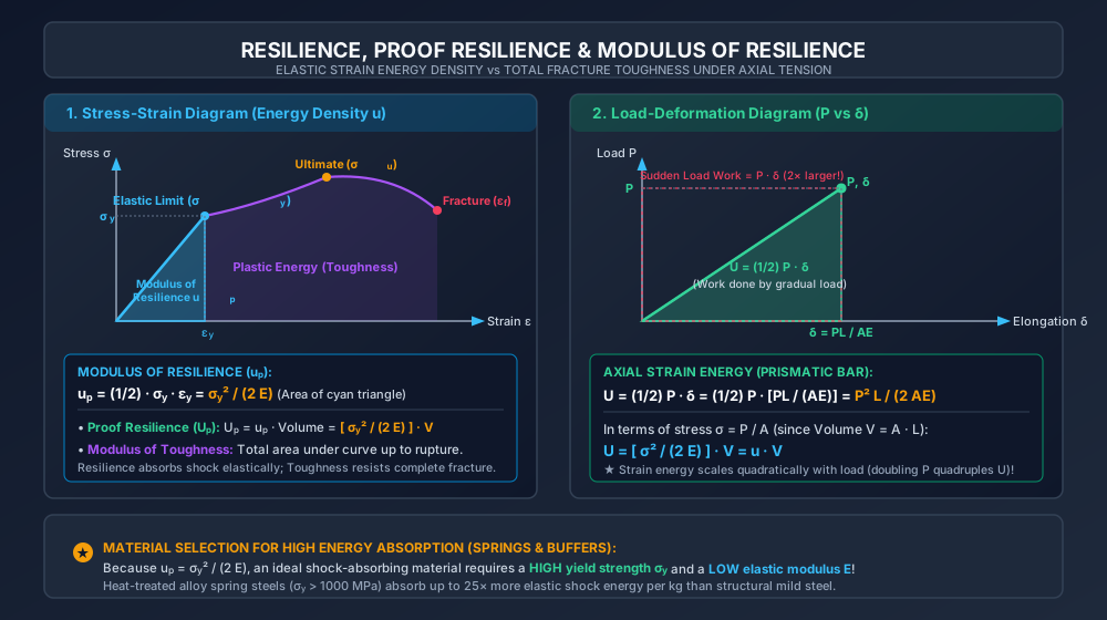
Proof Resilience is the maximum strain energy that can be absorbed by a body up to its elastic limit (or yield point) without undergoing permanent set:
For a prismatic body of volume under uniform stress:
where is the yield stress (or elastic limit stress) of the material.
3.4 Modulus of Resilience ()
The Modulus of Resilience is defined as the proof resilience per unit volume of the material. Geometrically, it equals the area under the linear elastic portion of the engineering stress-strain curve (up to the proportional limit):
Key Material Selection Insight: To maximize the Modulus of Resilience (), an ideal shock-absorbing material must possess:
- A high yield strength (),
- A low modulus of elasticity ().
This explains why mechanical springs and structural dampers are manufactured from high-strength heat-treated alloy steels (), which absorb up to more elastic shock energy per cubic metre than standard structural mild steel ().
3.5 Modulus of Toughness vs. Modulus of Resilience
| Property | Modulus of Resilience () | Modulus of Toughness () |
|---|---|---|
| Definition | Maximum energy absorbed per unit volume within the elastic limit. | Total energy absorbed per unit volume up to complete fracture / rupture. |
| Stress-Strain Area | Area of the linear elastic triangle up to . | Entire area under the complete stress-strain curve up to fracture . |
| Physical Significance | Measures resistance to elastic shock & vibration (spring action). | Measures resistance to impact fracture & catastrophic tearing. |
| Typical Value (Mild Steel) | ( larger than resilience!) | |
| Deformation Regime | Strictly elastic (). | Dominated by extensive plastic yielding and necking. |
4. Analytical Formulations for Axial Strain Energy
4.1 Prismatic Bar Subjected to Gradually Applied Load
Consider a prismatic bar of length , cross-sectional area , and Young's modulus . When an axial tensile load increases gradually from to , the elongation increases linearly from to .
The average load resisting deformation is . The external work done is:
Since :
Alternatively, expressing in terms of axial stress and volume :
4.2 Stepped Bar Under Axial Load
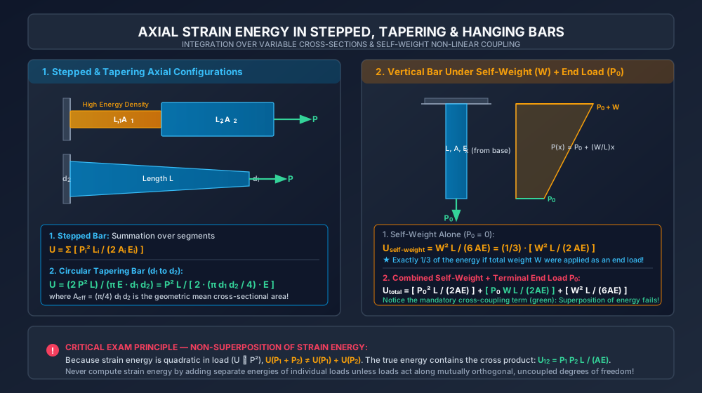
For a bar composed of distinct prismatic segments, each having length , cross-sectional area , and modulus , carrying axial force :
Crucial Energy Distribution Insight: Notice that for a given axial force , the strain energy stored in a segment scales inversely with area (). Consequently, the thinnest segment stores the overwhelming majority of the total strain energy and undergoes the highest stress concentration. In design of shock-absorbing bolts and tie rods, reducing the diameter of the shank to match the root diameter of the threads distributes strain energy uniformly, drastically increasing total impact capacity (waisted or reduced-shank bolts).
4.3 Circular Linearly Tapering Bar
Consider a circular bar of length whose diameter varies linearly from at to at subjected to an axial pull . The diameter at distance from the smaller end is:
The cross-sectional area at distance is:
The strain energy of an elemental slice of length is . Integrating over length :
where is the geometric mean area of the tapering bar.
4.4 Hanging Vertical Bar Under Self-Weight Alone
Consider a vertical bar of uniform cross-sectional area , length , unit weight , and total self-weight , fixed rigidly at the top end and hanging freely.
Choose coordinate measured upward from the free bottom end ( at bottom, at fixed top support).
The axial tensile force supported by a cross-section at height equals the weight of the bar segment hanging below it:
The strain energy stored in an elemental slice is . Integrating over the entire length:
High-Yield Exam Theorem: The strain energy stored in a vertical bar due to its own self-weight is exactly one-third () of the strain energy that would be stored if the entire self-weight were applied as an external concentrated load at the bottom end!
4.5 Vertical Bar Under Combined Self-Weight () and Terminal Load ()
If a concentrated downward pull is applied at the bottom end of the hanging bar, the axial tensile force at distance from the bottom becomes:
Squaring the internal force:
Integrating the strain energy:
5. Principle of Non-Superposition of Strain Energy
A foundational trap in structural mechanics is attempting to superimpose strain energies of separate loads.
In linear elasticity, stresses and displacements are linear functions of loads, so superposition strictly holds:
However, strain energy is a quadratic function of loads (). Therefore:
The Cross-Product Energy Term (): The term represents the mutual work done by load riding through the displacement produced by load .
- Simple superposition of strain energy () is valid if and only if the stresses/displacements caused by and are mutually orthogonal (e.g., an axial force and an uncoupled torsional moment).
- Whenever two loads cause stresses along the same degree of freedom, the cross-product term must be included!
6. SVG Technical Illustrations
6.1 Resilience & Modulus of Resilience
The illustration below demonstrates the geometric areas defining the Modulus of Resilience and Modulus of Toughness on the stress-strain curve, alongside the load-deformation work relationship.
6.2 Axial Strain Energy Configurations & Superposition
The diagram below details the axial energy distributions in stepped, tapering, and hanging bars, highlighting the self-weight factor and the mandatory cross-coupling energy term.
7. Solved Numerical Examples
Example 7.1: Resilience & Proof Resilience of Structural Steels
Problem Statement:
A circular mild steel tension rod of diameter and length () has a yield strength of and Young's modulus . The rod carries a working axial tensile load of .
- Calculate the working axial stress and total elongation .
- Determine the strain energy stored at the working load () and the strain energy density ().
- Determine the Proof Resilience () and Modulus of Resilience () of the rod.
- If an alloy spring steel of identical dimensions with and is used instead, calculate its modulus of resilience and compare its energy absorption capacity with mild steel.
Step-by-Step Solution:
-
Section Properties & Working Response:
- Cross-sectional area:
- Total volume of rod:
- Working stress:
- Elongation under working load:
-
Working Strain Energy () and Density ():
- Strain energy density:
(Verification: . Verified).
-
Proof Resilience & Modulus of Resilience (Mild Steel):
- Modulus of Resilience:
- Proof Resilience:
-
Comparison with High-Strength Alloy Steel ():
- Ratio of Resilience Capacities:
(Conclusion: The alloy steel provides higher elastic energy absorption capacity with zero increase in material volume or weight).
Example 7.2: Stepped Bar vs. Uniform Bar of Equal Volume
Problem Statement:
Two bars A and B are fabricated from the same steel (). Both bars have the same total length of and the same total volume .
- Bar B (Stepped): Consists of two cylindrical segments:
- Segment 1: Length , diameter .
- Segment 2: Length , diameter .
- Bar A (Uniform): Has a constant diameter along its full length such that .
An axial tensile load of is applied to both bars.
- Determine the diameter of the uniform bar.
- Calculate the strain energy stored in Bar A () and Bar B ().
- Determine the ratio and explain the physical reason for the difference.
Step-by-Step Solution:
-
Volume and Area Determinations:
- Bar B Segments:
- Bar A Dimensions (Equal Volume , ):
-
Strain Energy Calculations ():
- Bar A (Uniform):
- Bar B (Stepped):
- Segment 1:
- Segment 2:
- Total Strain Energy in Bar B:
-
Ratio & Physical Explanation:
(Bar B absorbs more strain energy than Bar A for identical material mass!)
- Physical Insight:
In Bar B, the axial stress in Segment 1 is , compared to in Bar A. Because strain energy density scales with stress squared (), the high stress in the thinner segment massively amplifies energy absorption. Notice that Segment 1 occupies only one-third of the length but accounts for two-thirds () of the total energy!
- Physical Insight:
Example 7.3: Deep Vertical Borehole Drill Pipe (Self-Weight + End Pull)
Problem Statement:
A heavy steel drill string hanging vertically in an exploratory borehole has a length of () and cross-sectional area .
Given: Steel density () and .
A drilling bit and bottom pull impose a terminal tensile load of at the free lower end.
- Calculate the total self-weight of the drill pipe.
- Calculate the strain energy stored if the terminal pull acted alone ().
- Calculate the strain energy stored if the self-weight acted alone ().
- Calculate the true total strain energy stored under simultaneous action of self-weight and end pull ().
- Calculate the cross-coupling energy term and verify that energy superposition fails.
Step-by-Step Solution:
-
Total Self-Weight ():
-
Strain Energy Due to Alone:
-
Strain Energy Due to Self-Weight Alone:
-
Cross-Coupling Mutual Work Term ():
-
True Total Strain Energy ():
- Verification of Superposition Failure: (Simply adding the two independent strain energies underestimates the true energy by or !).
8. Indian Standard Code Provisions & Engineering Practice
-
IS 800:2007 (General Construction in Steel — Section 12):
- Incorporates energy absorption criteria in the design of seismic bracing and tension tie rods.
- Requires reduced-shank (waisted) anchor bolts in heavy industrial foundations to ensure that under extreme earthquake tension, yielding and energy dissipation occur along the ductile unthreaded shank rather than by brittle stripping of thread roots.
-
IS 1893:2016 (Criteria for Earthquake Resistant Design of Structures):
- The Response Reduction Factor () directly accounts for a structure's ability to absorb earthquake energy through inelastic deformation (toughness) while maintaining elastic stability (resilience).
-
IS 1757:1988 (Method for Charpy Impact Test on Metallic Materials):
- Standard test method for determining the total notch impact energy absorption of structural steels at room and sub-zero temperatures.
- Specifies minimum absorbed energy requirements ( at specified temperatures) for structural steel grades (IS 2062).
9. Common Misconceptions & High-Yield Exam Traps
-
Superimposing Strain Energies Directly:
- Trap: Calculating .
- Correction: Strain energy is quadratic (). The cross-product term must be added whenever loads act in the same direction!
-
Self-Weight Strain Energy Factor ( vs. ):
- Trap: Thinking self-weight strain energy is or .
- Correction: Because axial force varies linearly from to , force squared varies quadratically (). Integrating produces , giving strictly .
-
Confusing Modulus of Resilience with Proof Resilience:
- Trap: Using Modulus of Resilience () when asked for total energy capacity ().
- Correction: Modulus of Resilience is an intensive material property (energy per unit volume: in ). Proof Resilience is an extensive property of the entire body ( in Joules).
-
Assuming Higher Modulus of Elasticity () Increases Resilience:
- Trap: Believing a stiffer material stores more elastic energy.
- Correction: Stiffer materials store less elastic energy for a given stress: . High resilience requires high and low !
-
Equating High Toughness to High Resilience:
- Trap: Thinking a tough material is automatically resilient.
- Correction: Mild steel is extremely tough () due to huge plastic ductility, but has low resilience (). Spring steel has high resilience but lower toughness.
10. Previous Year Competitive Exam Questions
Question 1 (GATE CE — 1 Mark)
The strain energy stored in a solid uniform bar of length , cross-sectional area , and elastic modulus due to its own weight hanging vertically is:
- (A)
- (B)
- (C)
- (D)
Answer: (C)
Solution:
.
.
Question 2 (UPSC ESE)
The Modulus of Resilience of a material is defined as:
- (A) Strain energy stored per unit volume up to proportional limit
- (B) Total strain energy stored up to fracture
- (C) Maximum load a material can carry without yielding
- (D) Ratio of proof stress to yield stress
Answer: (A)
Solution:
Modulus of resilience is the strain energy density stored in the material when stressed up to the proportional limit / elastic limit: .
Question 3 (SSC JE)
If the diameter of an axially loaded circular bar is doubled while keeping the load and length constant, the strain energy stored will become:
- (A) 2 times
- (B) 4 times
- (C) of original
- (D) of original
Answer: (C)
Solution:
. Area . When diameter is doubled (), area increases by (). Therefore, .
Question 4 (State AE)
Two bars of the same material and length have diameters and respectively. If both bars are subjected to the same tensile load , the ratio of strain energy stored in the first bar to that in the second bar is:
- (A)
- (B)
- (C)
- (D)
Answer: (C)
Solution:
.
.
11. Comprehensive Summary & Formula Sheet
| Parameter / Configuration | Mathematical Formula | Key Assumptions & Conditions |
|---|---|---|
| Strain Energy Density () | Linearly elastic material (Hooke's Law) | |
| Modulus of Resilience () | Area of elastic triangle up to yield stress | |
| Proof Resilience () | Maximum elastic energy capacity of entire body | |
| Prismatic Bar Under Load | Gradually applied axial load, uniform area | |
| Stepped Bar | Thinnest segment stores highest energy share | |
| Circular Tapering Bar () | (geometric mean area) | |
| Vertical Bar Under Self-Weight | Triangular axial force distribution | |
| Self-Weight to End Load Ratio | Fundamental structural theorem | |
| Combined Self-Weight + Load | Mandatory cross-coupling term: Superposition fails! | |
| Cross-Product Energy Term () | Mutual work done by through |