While Euler's formula governs long, slender columns failing by pure elastic buckling (λ>89 for mild steel) and direct crushing governs stubby pedestals (λ<32), the vast majority of practical civil engineering compression members fall squarely in the intermediate range (32≤λ≤120). In this intermediate regime, failure occurs through a complex interaction of material plastic yielding and geometric flexural instability.
Furthermore, real-world columns are almost never subjected to mathematically concentric axial loads. Beams framing into columns, fabrication tolerances, initial crookedness (e0), and connection eccentricities introduce simultaneous axial force and bending moment.
To address these real-world realities, two monumental theoretical formulations were developed:
The Rankine-Gordon Empirical Formula: An elegant reciprocal formulation that bridges the gap between pure material crushing and pure elastic buckling, valid across all slenderness ratios.
The Secant Formula: An exact analytical derivation that accounts for the non-linear second-order lateral deflection (P−Δ effect) caused by an eccentric compressive load.
Mastering both formulations is essential for competitive examinations (GATE CE, UPSC ESE, SSC JE, State AE) and practical structural design.
2. The Intermediate Column Dilemma & The Rankine Principle
2.1 The Intermediate Gap
Consider the two theoretical extremes of compression failure:
Short Column Failure: Governed purely by the material ultimate compressive crushing strength:
Pc=σc⋅A
Long Column Failure: Governed purely by Euler's elastic flexural buckling load:
Pe=Le2π2EI=λ2π2EA
In intermediate columns, testing shows that the actual failure load P is strictly less than both the crushing load Pc and the Euler load Pe:
Pactual<min(Pc,Pe)
2.2 The Reciprocal Hypothesis
William John Macquorn Rankine (1820–1872) proposed an empirical reciprocal formulation combining both crushing and buckling resistances:
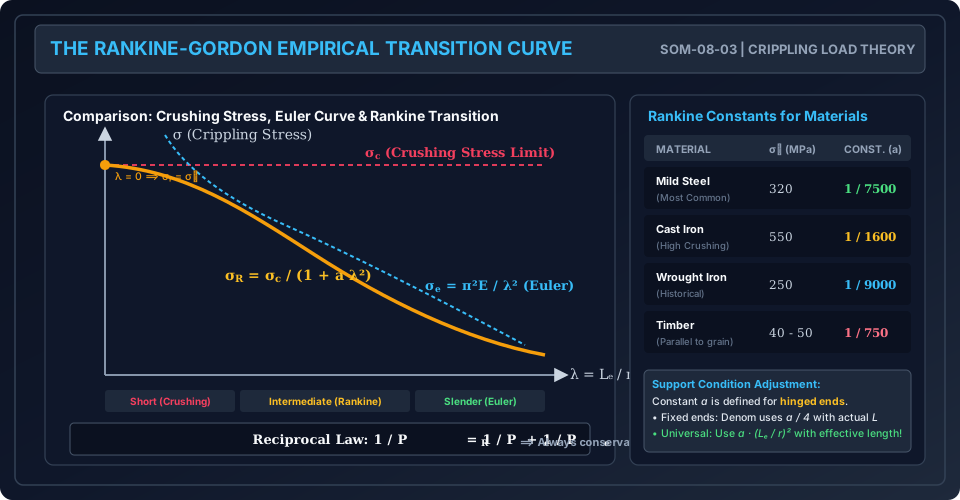
PR1=Pc1+Pe1
where PR is the Rankine Crippling (or Buckling) Load.
3. Mathematical Derivation of the Rankine-Gordon Formula
Starting from the reciprocal equation:
PR1=Pc1+Pe1=Pc⋅PePe+Pc
Inverting both sides:
PR=Pc+PePc⋅Pe=1+PePcPc
Substitute the analytical expressions for Pc=σc⋅A and Pe=λ2π2EA:
PePc=λ2π2E⋅Aσc⋅A=(π2Eσc)λ2
Define the Rankine Constant (a):
a=π2Eσc
Substituting this into the equation yields the classical Rankine-Gordon Formula:
PR=1+aλ2σc⋅A=1+a(rminLe)2σc⋅A
Dividing by the cross-sectional area A gives the Rankine Crippling Stress (σR):
σR=APR=1+aλ2σc
3.3 Asymptotic Verification of the Formula
Case 1: Very Short Column (λ→0):aλ2→0⟹PR→1+0σcA=σcA=Pc
The formula perfectly reproduces the pure material crushing capacity.
Case 2: Very Slender Column (λ→∞):aλ2≫1⟹PR≈aλ2σcA=(π2Eσc)λ2σcA=λ2π2EA=Pe
The formula smoothly merges into Euler's elastic buckling load.
Because the reciprocal sum PR1=Pc1+Pe1 always produces a result smaller than either individual term, the Rankine-Gordon formula provides a smooth, continuous, and universally conservative prediction across the entire spectrum of slenderness ratios (0≤λ≤∞).
4. Empirical Constants for Engineering Materials
While theoretical a=π2Eσc, practical testing shows that material imperfections and residual stresses alter the curvature. Consequently, engineering handbooks and standard codes adopt empirically calibrated values of σc and a (established for hinged ends):
Material
Crushing Stress (σc)
Rankine Constant (a) for Hinged Ends
Theoretical λc=1/a
Mild Steel
320 MPa
75001
≈86.6
Cast Iron
550 MPa
16001
≈40.0
Wrought Iron
250 MPa
90001
≈94.9
Structural Timber
40−50 MPa
7501
≈27.4
Aluminum Alloy
200 MPa
50001
≈70.7
4.1 Adjusting Rankine's Constant for Different End Conditions
The standard Rankine constant a listed in tables is defined for a hinged-hinged column (Le=L). If the column has different end conditions:
Best Practice: Always use the universal effective length formulation:
PR=1+a(rLe)2σc⋅A
Alternative Textbook Notation (using actual length L):
Hinged - Hinged (Le=L): Denominator is 1+a(L/r)2.
Fixed - Fixed (Le=L/2): Denominator is 1+4a(L/r)2.
Fixed - Hinged (Le=L/2): Denominator is 1+2a(L/r)2.
Fixed - Free (Le=2L): Denominator is 1+4a(L/r)2.
5. Eccentrically Loaded Columns & Derivation of the Secant Formula
In structural reality, loads are rarely concentric. Consider a pinned-pinned column of length L subjected to an axial compressive load P acting at an eccentricity e from the centroidal axis.
      P (Eccentric Load)
      ▼  e
     ──┬── (Top Hinge)
       │
       │\
       │ \
       │  ) δ_max (Mid-Height Lateral Deflection)
       │ /
       │/
     ──┴── (Bottom Hinge)
      ▲  e
      P
5.1 Governing Differential Equation
Choose coordinate origin at the mid-height of the column (x=0 at mid-height, x=±L/2 at the ends). Let y(x) be the lateral deflection of the centroidal axis from its initial position:
At any cross-section x, the total distance from the line of action of load P to the deflected centroid is e+y(x).
The internal bending moment is:
M(x)=−P[e+y(x)]
Equating to flexural curvature:
EIdx2d2y=−P[e+y(x)]⟹dx2d2y+k2y=−k2e
where k2=EIP.
5.2 General Solution & Boundary Conditions
The general solution to this non-homogeneous ODE is:
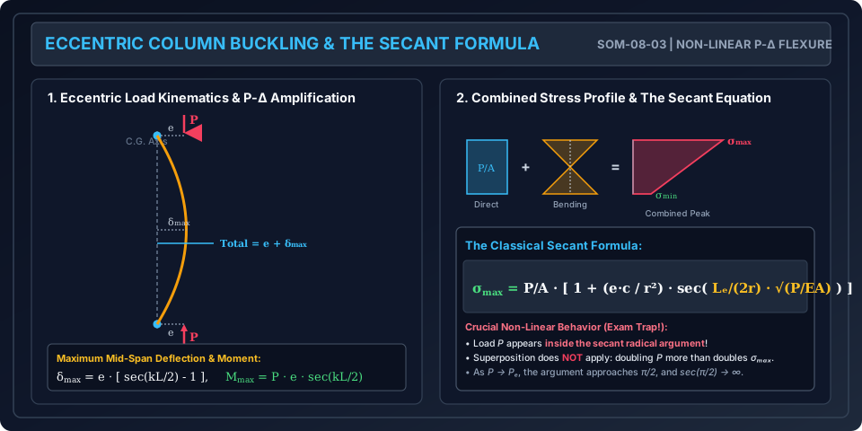
Physical Insight (P−Δ Amplification): In elementary mechanics, the bending moment due to an eccentric load is simply M=P⋅e. However, due to lateral deflection of the column, the bending moment is magnified by the factor sec(kL/2)! This magnification factor approaches infinity as kL/2→π/2 (which corresponds to P→Pe).
5.4 The Secant Formula for Peak Stress
The maximum compressive stress σmax occurs at the extreme concave fiber at mid-height:
σmax=σdirect+σbending=AP+IMmax⋅c
where:
c = Distance from the neutral axis to the extreme compression fiber (c=D/2 or d/2).
6. Non-Linearity & The Failure of Superposition in Beam-Columns
The Secant Formula reveals a profound departure from elementary beam theory:
Non-Linear Load-Stress Relationship: The applied load P appears both outside and inside the radical argument of the secant function.
Failure of the Principle of Superposition: If the compressive load P is doubled, the peak stress σmaxmore than doubles:
σmax(2P)≫2⋅σmax(P)
Design Implication: In sizing an eccentric column to an allowable stress σallow, one cannot simply apply a factor of safety to the stress. The factor of safety (FOS) must be applied to the load P directly (Pdesign=FOS×Pservice), and the resulting maximum stress must not exceed the yield stress σy.
7. Engineering Diagrams & Visual Walkthrough
Figure 1: The Rankine-Gordon Transition Curve & Empirical Constants
The following diagram illustrates how the Rankine-Gordon empirical curve seamlessly bridges the crushing stress threshold σc and the asymptotic Euler hyperbola, along with the empirical material constant table.
Figure 2: Eccentric Column Kinematics & The Secant Formula
The following diagram details the second-order P−Δ amplification mechanism, the combined direct and flexural stress distribution across the cross-section, and the structure of the Secant Formula.
8. Worked Numerical Examples
Example 1: Rankine Crippling Load of a Hollow Cast Iron Column
Problem Statement: A hollow cast iron column of outside diameter Do=200 mm and inside diameter Di=150 mm is 5.0 m long with both ends rigidly fixed (Le=0.5L=2.5 m).
Given:
Compressive crushing strength: σc=550 MPa
Rankine's constant for hinged ends: a=16001
Modulus of Elasticity: E=100 GPa
Factor of safety: FOS=3.0
Calculate the Rankine crippling load PR.
Calculate the Euler critical load Pe.
Compare the Rankine load with both the pure crushing load Pc and the Euler load Pe.
Determine the safe working load Psafe.
Solution:
Step 1: Cross-Sectional Geometric Properties:
Cross-sectional Area A:
A=4π(Do2−Di2)=4π[(0.200)2−(0.150)2]=4π[0.0400−0.0225]=0.013744 m2=137.44 cm2
Moment of Inertia I:
I=64π(Do4−Di4)=64π[(0.200)4−(0.150)4]=64π[1.600×10⁻³−0.50625×10⁻³]I=64π×1.09375×10−3=5.36893×10⁻⁵ m4=5368.93 cm4
Radius of Gyration r:
r=AI=0.0137445.36893×10−5=0.06250 m=62.50 mm(Alternatively: r=4Do2+Di2=40.0400+0.0225=40.250=0.0625 m)
Step 2: Effective Length & Slenderness Ratio:
Since both ends are fixed:
(Note: Using the theoretical reciprocal relation: PR=Pc+PePc⋅Pe=7559.46+8478.287559.46×8478.28=3996.27 kN)
Step 5: Safe Working Load (Psafe):
Psafe=FOSPR=3.03779.73 kN=1259.91 kN
Key Observation: Because λ=40 lies in the intermediate zone where crushing and buckling interact strongly, the Rankine crippling load (3780 kN) is less than half of the Euler load (8478 kN). Relying on Euler's formula would have resulted in catastrophic failure!
Example 2: Structural Column Selection Using Rankine's Formula
Problem Statement: A structural steel column of length L=4.5 m with one end fixed and one end hinged (Le=0.707L=3.1815 m) must support a working axial load W=350 kN with a factor of safety FOS=2.5 (Required crippling load PR(req)=2.5×350=875 kN).
Mild steel properties: σc=320 MPa, Rankine constant a=75001.
Two rolled steel sections are available:
Trial Section A (ISMB 350): Area A=66.7 cm2, rxx=14.29 cm, ryy=2.84 cm.
Trial Section B (ISWB 300 - Wide Flange): Area A=61.3 cm2, rxx=12.87 cm, ryy=4.82 cm.
Determine which section is safe under the Rankine formula, and compare their material efficiency.
Solution:
The column is unbraced laterally; therefore, buckling is governed by the least radius of gyration (rmin=ryy).
Profound Design Takeaway: The wide-flange section (ISWB 300) saves 8.1% in steel weight while delivering 55.4% more buckling capacity! The wider flanges significantly boost the weak-axis radius of gyration (ryy increased from 28.4 mm to 48.2 mm), dramatically slashing the slenderness ratio.
Example 3: Peak Stress in an Eccentric Column via the Secant Formula
Problem Statement: A solid rectangular steel column of width b=100 mm and depth h=150 mm has a length L=3.0 m and is pinned at both ends (Le=L=3.0 m).
Material properties: E=200 GPa=200×103 N/mm2.
An axial compressive load P=250 kN is applied with an eccentricity e=15 mm along the symmetry axis, causing bending about the minor axis (b=100 mm).
Calculate the maximum mid-height lateral deflection δmax.
Calculate the maximum compressive stress σmax using the Secant Formula.
Compare with the elementary linear estimate that ignores lateral deflection amplification.
Solution:
Step 1: Cross-Sectional Geometric Properties:
Area: A=b⋅h=100×150=15,000 mm2=0.015 m2.
Bending occurs about the minor axis (b=100 mm):
I=12h⋅b3=12150×(100)3=12.50×106 mm4=1.25×10⁻⁵ m4
Radius of gyration r:
r=12b=3.4641100=28.8675 mm=0.0288675 m
Distance to extreme compression fiber:
c=2b=2100=50.0 mm=0.050 m
Stress Underestimation: The elementary method underestimates the true flexural stress by a factor equal to sec(u)=1.1241 (12.4% underestimation of the bending component).
9. Perry-Robertson Formula & Modern Code Formulations
In modern steel structures (IS 800:2007 and Eurocode 3), neither pure Euler nor empirical Rankine is used directly for sizing. Instead, design is based on the Perry-Robertson Formula, which analytically incorporates an initial geometric out-of-straightness e0:
(σy−σ)(σe−σ)=η⋅σe⋅σ
where:
σe=λ2π2E (Euler stress).
η=α(λ−0.2) is the imperfection parameter, with α representing the imperfection factor for different column buckling classes:
Class a (α=0.21): Hot rolled I-sections with thick flanges (highest quality).
Class b (α=0.34): Standard rolled I-sections, RHS/SHS hollow tubes.
Class c (α=0.49): Standard channels, angles, built-up welded sections.
Class d (α=0.76): Heavy welded box sections, thick plates.
10. Common Misconceptions & Exam Pitfalls
[!WARNING] Pitfall 1: Assuming Superposition Holds for Eccentrically Loaded Columns
In beams, doubling the lateral load doubles the stress. In columns, doubling the axial load P increases the secant argument 2rLeEAP, causing sec(u) to grow rapidly. Stress grows non-linearly. Superposition is completely invalid.
[!CAUTION] Pitfall 2: Neglecting End Restraint in the Rankine Constant
The constant a=1/7500 (mild steel) is strictly for pinned ends. When using actual length L for a fixed-fixed column, the denominator must use a/4, or simply use the effective length Le=0.5L with the original constant a.
[!NOTE] Pitfall 3: Inverting the Rankine Reciprocal Expression
The formula is PR1=Pc1+Pe1. Some students mistakenly write PR=Pc+Pe, which gives an absurd load greater than both! Remember: PR is always strictly less than both Pc and Pe.
11. Real-World Engineering Applications & Standard Codes
Building Column Design in IS 800:2007 (Section 7):
Structural steel columns are classified into 4 buckling curves (a,b,c,d) based on cross-section geometry, flange thickness, and residual stresses.
Design compressive strength fcd=ϕ+[ϕ2−λ2]0.5fy/γm0, where ϕ=0.5[1+α(λ−0.2)+λ2].
Reinforced Concrete Columns in IS 456:2000 (Clause 25.1.2):
A compression member is classed as "short" when both slenderness ratios Lex/D and Ley/b are less than 12. If either exceeds 12, it is designed as a slender column with additional second-order moments (P−Δ effects).
Transmission Towers and Trusses:
Slender angle sections used as tower diagonals must have their effective length adjusted for bolt end fixity (IS 802 Part 1).