Thin Cylinders and Spherical Shells Under Internal Pressure
In this chapter (3 topics)
On this page
- 1. Topic Title & Metadata Header
- 2. Introduction & Physical Engineering Significance
- 3. Foundational Assumptions & Governing Criteria
- 4. Mathematical Derivations of Membrane Stresses
- 4.1 Circumferential (Hoop) Stress in a Thin Cylinder (σh)
- 4.2 Longitudinal (Axial) Stress in a Thin Cylinder (σL)
- 4.3 Fundamental Stress Ratio
- 4.4 Membrane Stress in a Thin Spherical Shell (σsphere)
- 5. State of Stress & 3D Mohr's Circle Analysis
- 5.1 Maximum In-Plane Shear Stress vs. Absolute Maximum Shear Stress
- 5.2 Shear Stress in a Thin Spherical Shell
- 5.3 Yield Criteria Comparison for Thin Cylinders
- 6. Architectural Comparison & Structural Shell Efficiency
- 7. SVG Technical Illustrations
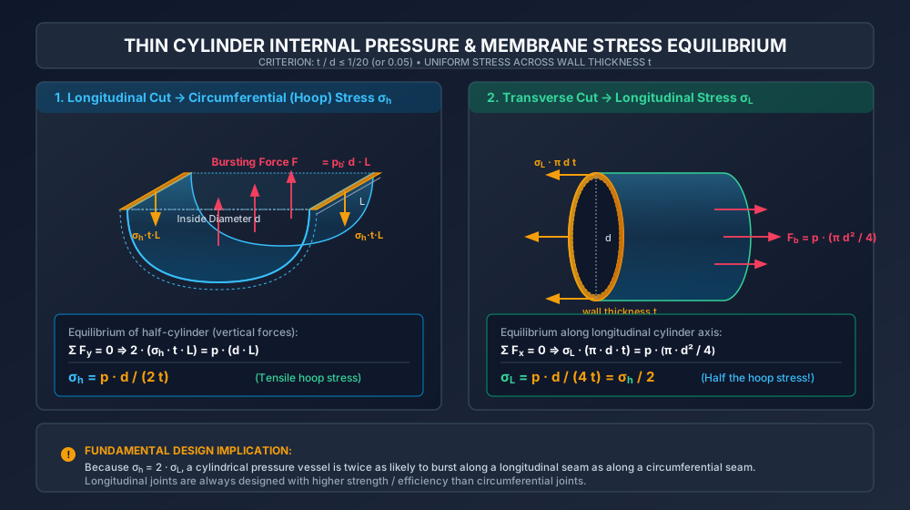
- 7.1 Thin Cylinder Membrane Stress Equilibrium
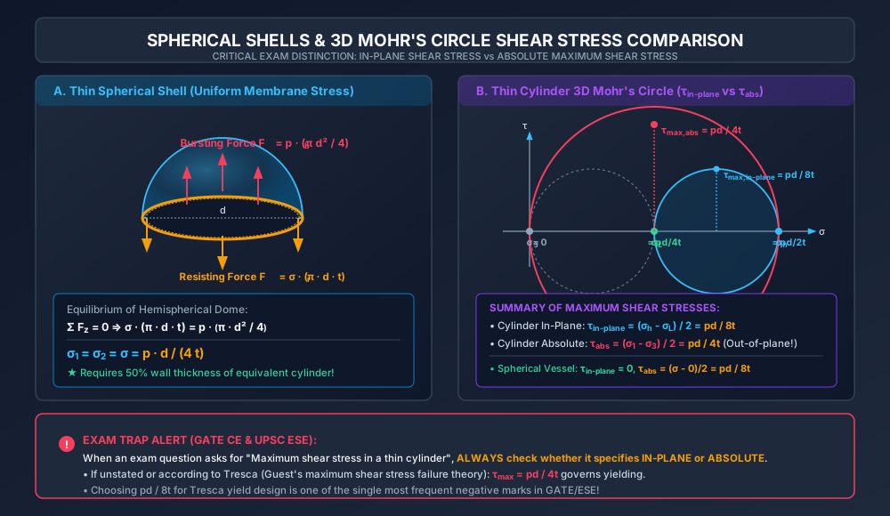
- 7.2 Spherical Shell Membrane Stress & 3D Mohr's Circle
- 8. Solved Numerical Examples
- Example 8.1: Air Receiver Stress & Maximum Permissible Pressure
- Example 8.2: Comparative Steel Mass — Spherical vs. Cylindrical Storage Vessel
- Example 8.3: Combined Internal Pressure and Applied Torsion (GATE Advanced Level)
- 9. Indian Standard Code Provisions & Engineering Practice
- 10. Common Misconceptions & High-Yield Exam Traps
- 11. Previous Year Competitive Exam Questions
- Question 1 (GATE CE — 2 Marks)
- Question 2 (UPSC ESE — Objective)
- Question 3 (SSC JE / State AE)
- Question 4 (GATE CE — Numerical Answer Type)
- 12. Comprehensive Summary & Formula Sheet
1. Topic Title & Metadata Header
- Topic ID:
SOM-09-01 - Module / Subject: Strength of Materials (Mechanics of Solids)
- Chapter 09: Thin and Thick Cylinders & Spherical Shells
- Topic Title: Thin Cylinders and Spherical Shells Under Internal Fluid Pressure
- Prerequisites:
SOM-01-01(Stress and Strain Definitions),SOM-02-01toSOM-02-03(Biaxial Stress Transformation & Mohr's Circle),SOM-02-05(Theories of Failure). - Target Examinations: GATE CE, UPSC ESE (Civil), SSC JE (Civil), State AE/JE, RRB JE (Civil).
- Quality Assurance Gate: Level 1 through Level 7 Verification Protocol Enforced.
2. Introduction & Physical Engineering Significance
In civil, mechanical, and petrochemical infrastructure, fluid containment structures operating under positive internal pressure are ubiquitous. Common civil engineering examples include:
- Municipal water supply penstocks and trunk distribution mains,
- Steel rising mains in sewage pumping systems,
- High-pressure compressed air receivers in tunneling and pneumatic foundation caissons,
- Gas storage vessels and liquefied petroleum gas (LPG) spherical bullets ("Hortonspheres"),
- Submerged hydraulic tunnels subjected to internal hydrodynamic head.
When a vessel contains fluid under internal gauge pressure , the contained fluid exerts a normal pressure uniformly outward against all internal surfaces. This pressure induces tensile membrane stresses in the vessel walls.
Depending on the ratio of wall thickness to internal diameter , pressure vessels are fundamentally classified into two distinct mechanical regimes:
- Thin Shells ( or ): The radial variation of stress across the wall thickness is negligible (). Stresses can be treated as uniformly distributed across the wall thickness (membrane state of stress).
- Thick Shells (): Radial stress cannot be ignored, and circumferential stress varies hyperbolically across the wall, requiring Lamé's differential equations (
SOM-09-03).
3. Foundational Assumptions & Governing Criteria
Thin shell membrane theory rests upon the following core engineering assumptions:
- Geometry Criterion: The wall thickness is small compared to the internal diameter , satisfying: For most commercial pipelines and vessels ( typically ranges from to ).
- Uniform Stress Across Thickness: Because , bending stiffness of the shell wall is neglected. The circumferential (hoop) stress and longitudinal stress are assumed perfectly uniform throughout the wall thickness .
- Radial Stress Neglect: The radial stress varies from compressive magnitude at the inner surface to (atmospheric) at the outer surface. Since (by a factor of ), radial compressive stress is neglected when calculating membrane yielding, treating the vessel wall as a state of plane stress ().
- Fluid Statically Maintained: The internal fluid has negligible shearing resistance and exerts purely normal pressure perpendicular to the metal boundary.
- No End Discontinuity Effects: Away from rigid flanges, end caps, and support saddles, the membrane state is free from secondary bending moments (Saint-Venant's principle).
4. Mathematical Derivations of Membrane Stresses
4.1 Circumferential (Hoop) Stress in a Thin Cylinder ()
Consider a thin cylindrical shell of inside diameter , wall thickness , length , containing fluid under internal gauge pressure .
To determine the circumferential stress, consider a virtual longitudinal cutting plane passing through the diametral centerline of the cylinder, dividing it into two symmetrical semicircular halves.
       PROJECTED AREA = d × L
       BURSTING FORCE F_b = p · d · L  (acting vertically upward)
       RESISTING FORCE F_r = 2 · (σ_h · t · L)  (acting vertically downward)
-
Total Upward Bursting Force (): The internal pressure acts normal to every point of the curved semicircular inner wall. Consider an elemental strip at angle subtending an angle :
The radial bursting force on this strip is . Resolving vertically:
Integrating over the semicircle from to :
(Physical Principle: The resultant fluid force in any direction equals the pressure multiplied by the projected area perpendicular to that direction: .)
-
Total Downward Resisting Force (): The shell wall cut exposes two rectangular cross-sections of area on each side:
The total tensile resisting force developed in the wall is:
-
Equilibrium Equation: Equating bursting force to resisting force ():
Cancelling length from both sides:
4.2 Longitudinal (Axial) Stress in a Thin Cylinder ()
To find the longitudinal stress resisting the axial bursting force on closed end caps, consider a transverse cutting plane perpendicular to the longitudinal axis of the cylinder.
-
Total Axial Bursting Force (): The internal pressure acts on the circular end cap of internal area :
-
Total Axial Resisting Force (): The transverse cut exposes an annular metal ring of inside diameter and thickness . For a thin cylinder, the cross-sectional area of the annular ring is approximated by its mean circumference multiplied by thickness:
The resisting force developed by uniform longitudinal tensile stress is:
-
Equilibrium Equation: Equating axial forces along the cylinder axis ():
Cancelling :
4.3 Fundamental Stress Ratio
Comparing the two principal membrane stresses:
Key Design Insight: The circumferential (hoop) stress is twice as large as the longitudinal stress. Consequently:
- A thin cylinder subjected to excessive internal pressure will always rupture longitudinally (splitting along its length), not circumferentially.
- In fabricated or welded steel pipes, longitudinal welded joints carry twice the stress of circumferential joints. Longitudinal seams must be designed with higher joint efficiency or subjected to stricter non-destructive testing (NDT).
4.4 Membrane Stress in a Thin Spherical Shell ()
Consider a thin spherical pressure vessel of internal diameter and wall thickness subjected to internal fluid pressure .
By spherical symmetry, any plane passing through the center of the sphere divides it into two identical hemispherical bowls.
- Bursting Force on Projected Circular Area:
- Resisting Force in Annular Wall Rim:
- Equilibrium ():
Because of complete spherical point-symmetry, every normal direction in the tangent plane of the sphere is a principal direction, and the two principal stresses are equal:
5. State of Stress & 3D Mohr's Circle Analysis
An elemental block taken from the surface of a thin cylindrical pressure vessel is subjected to a triaxial state of stress:
(Note: On the inner wall surface, . Since , the ratio . Neglecting introduces an error under , which is standard for thin shell analysis.)
5.1 Maximum In-Plane Shear Stress vs. Absolute Maximum Shear Stress
This is one of the most critical and frequently tested distinctions in GATE CE and UPSC ESE:
-
Maximum In-Plane Shear Stress (): The maximum shear stress acting on planes perpendicular to the cylinder surface (rotated between the hoop and longitudinal axes):
-
Absolute Maximum Shear Stress (): The true maximum shear stress in the 3-dimensional material occurs on planes inclined at to the vessel surface, cutting through the wall thickness (governed by the largest and smallest principal stresses and ):
Crucial Warning:
If a ductile pressure vessel yields according to Tresca's Maximum Shear Stress Theory, yielding begins when:
Calculating Tresca yield using underestimates the actual shear stress by and produces a catastrophic, unsafe design!
5.2 Shear Stress in a Thin Spherical Shell
For a spherical vessel:
- In-Plane Shear Stress: (All in-plane planes are principal planes; in-plane Mohr's circle degenerates to a single point!)
- Absolute Maximum Shear Stress:
5.3 Yield Criteria Comparison for Thin Cylinders
For a thin cylinder governed by yield strength :
- Tresca (Maximum Shear Stress Theory):
- von Mises (Distortion Energy Theory): Substituting : Setting : (Von Mises theory predicts a 15.5% higher pressure containment capacity, or 13.4% thinner wall, than Tresca for cylindrical pressure vessels.)
6. Architectural Comparison & Structural Shell Efficiency
| Metric / Parameter | Thin Cylindrical Vessel | Thin Spherical Vessel | Cylindrical with Hemispherical Ends |
|---|---|---|---|
| Governing Membrane Stress | (body), (heads) | ||
| Required Wall Thickness () | , | ||
| Volume-to-Surface Ratio | Moderate ( for long cylinder) | Maximum theoretical () | High |
| Material Mass for Given Volume | Higher (Baseline ) | Lowest (Saves to steel mass) | Economical compromise |
| Manufacturing Complexity | Low (roll plate into cylinder, straight seams) | High (dishing/pressing double-curvature petals) | Standard industrial practice |
| Typical Practical Use | Pipes, boilers, air receivers, silos | High-capacity gas storage bullets, space craft | High-pressure commercial vessels |
7. SVG Technical Illustrations
7.1 Thin Cylinder Membrane Stress Equilibrium
The diagram below illustrates the free body diagrams for the longitudinal diametral cut (yielding hoop stress ) and the transverse circular cut (yielding longitudinal stress ).
7.2 Spherical Shell Membrane Stress & 3D Mohr's Circle
The diagram below shows the hemispherical cut equilibrium, the 3D Mohr's circles comparing in-plane vs. absolute maximum shear stresses, and the crucial exam pitfalls.
8. Solved Numerical Examples
Example 8.1: Air Receiver Stress & Maximum Permissible Pressure
Problem Statement:
A cylindrical compressed air receiver has an internal diameter of and a wall thickness of . The internal working pressure is ().
- Verify whether the thin cylinder theory applies.
- Calculate the circumferential (hoop) stress and longitudinal stress in the shell.
- Determine the maximum in-plane shear stress and the absolute maximum shear stress.
- If the permissible tensile stress for the steel plate is , determine the factor of safety under current operating pressure, and the maximum safe working pressure .
Step-by-Step Solution:
-
Check Thin Cylinder Applicability:
Since (), thin cylinder membrane theory is strictly valid.
-
Membrane Stresses:
- Circumferential (Hoop) Stress:
- Longitudinal Stress:
-
Shear Stresses:
- Maximum In-Plane Shear Stress:
- Absolute Maximum Shear Stress: With , , and :
-
Factor of Safety & Maximum Permissible Pressure:
- Factor of Safety (governed by maximum normal stress ):
- Maximum Safe Working Pressure ():
Example 8.2: Comparative Steel Mass — Spherical vs. Cylindrical Storage Vessel
Problem Statement:
A chemical plant requires a pressurized storage vessel with a capacity of to store gas at an internal pressure of . The permissible tensile stress of the steel is , and steel density is . Compare:
- A completely spherical vessel.
- A cylindrical vessel with hemispherical ends whose total cylindrical length equals twice its diameter ().
(Assume the hemispherical ends are sized to the required spherical thickness and disregard joints/nozzles).
Determine the dimensions, required wall thicknesses, total metal masses, and the percentage steel mass saved by choosing the spherical design.
Step-by-Step Solution:
-
Spherical Vessel Design:
- Internal Volume:
- Required Wall Thickness ():
- Surface Area & Metal Mass:
-
Cylindrical Vessel with Hemispherical Ends ():
- Internal Volume (Cylinder + Two Hemispheres = Cylinder + Sphere):
- Required Wall Thicknesses:
- Cylindrical body:
- Hemispherical heads:
- Metal Volume and Mass:
- Cylindrical shell:
- Two hemispherical heads (full sphere surface):
- Total metal volume:
- Total cylinder mass:
-
Comparison & Mass Savings:
(Conclusion: The spherical vessel achieves an immediate reduction in total required steel mass for identical storage volume and pressure containment).
Example 8.3: Combined Internal Pressure and Applied Torsion (GATE Advanced Level)
Problem Statement:
A thin-walled circular cylindrical steel shaft of internal diameter and wall thickness is subjected simultaneously to an internal fluid pressure of and an external twisting torque .
- Calculate the normal stresses due to internal pressure.
- Calculate the torsional shear stress in the shell wall using thin-tube theory.
- Determine the principal stresses and at the outer surface.
- Determine the maximum in-plane shear stress and absolute maximum shear stress.
- Determine the orientation of the principal planes with respect to the longitudinal axis of the shaft.
Step-by-Step Solution:
-
Normal Stresses from Internal Pressure:
-
Torsional Shear Stress (): Using thin-walled circular tube torsion formula (mean radius ):
(Alternatively, using Bredt-Batho shear flow : , . Exactly identical).
-
Principal Stresses (): Taking coordinate axes: longitudinal axis (), hoop axis (), .
- Average Normal Stress:
- Radius of Mohr's Circle ():
- Major Principal Stress:
- Minor Principal Stress:
-
Maximum Shear Stresses:
- Maximum In-Plane Shear Stress:
- Absolute Maximum Shear Stress (since on outer surface):
-
Orientation of Principal Planes:
(Or relative to the circumferential hoop direction).
9. Indian Standard Code Provisions & Engineering Practice
-
IS 2825:1969 (Code for Unfired Pressure Vessels):
- Classifies vessels into Class I (severe duties, toxic/lethal fluids, high pressure), Class II (medium service), and Class III (light duty, water supply).
- Specifies joint efficiencies ():
- Fully radiographed double-welded butt joint: .
- Spot radiographed butt joint: .
- Non-radiographed welded joint: .
- Pressure vessel design formulas incorporate joint efficiency: where is the statutory corrosion allowance (typically to for carbon steel exposed to water/steam).
-
IS 5822:1994 (Code of Practice for Laying of Welded Steel Pipes for Water Supply):
- Stipulates minimum wall thickness based on internal working pressure, surge head (water hammer), and external earth cover loads.
- Requires field hydrostatic testing at working pressure or design pressure, whichever is greater.
-
ASME Boiler and Pressure Vessel Code (BPVC) Section VIII, Division 1:
- Incorporates the mid-radius correction for thin cylindrical shells under internal pressure: where is allowable stress and is joint efficiency. When , this simplifies precisely to the classic thin-shell formula .
10. Common Misconceptions & High-Yield Exam Traps
-
Confusing In-Plane vs. Absolute Maximum Shear Stress:
- Trap: When asked for "maximum shear stress", calculating .
- Correction: The absolute maximum shear stress in a cylinder is . Always select unless the question explicitly specifies in-plane.
-
In-Plane Shear in a Sphere is ZERO, not :
- Trap: Assuming the sphere has in-plane shear .
- Correction: In a spherical vessel, . Therefore, in-plane shear . The value is its absolute maximum shear stress ().
-
Confusing Inside vs. Outside Diameter in :
- Trap: Using outside diameter instead of inside diameter without adjusting.
- Correction: The internal fluid acts directly across the internal diameter . In strict theoretical derivations, bursting force uses internal diameter (or mean diameter ). In thin shells where , the difference between , , and is , but exam numericals strictly specify internal diameter.
-
Assuming Longitudinal Joint Resists Longitudinal Stress:
- Trap: Thinking a longitudinal welded seam resists longitudinal stress .
- Correction: A longitudinal joint runs parallel to the cylinder axis; opening this joint requires circumferential tension. Therefore, longitudinal seams resist circumferential (hoop) stress , while circumferential (girth) seams resist longitudinal stress !
-
Failure Mode of Pressurized Cylinders:
- Trap: Expecting cylindrical pipes to burst into two halves crosswise.
- Correction: Because , a pressurized pipe splits longitudinally along its length like an overcooked sausage.
11. Previous Year Competitive Exam Questions
Question 1 (GATE CE — 2 Marks)
A thin cylindrical shell of diameter , length , and wall thickness is subjected to internal pressure . The ratio of circumferential stress to longitudinal stress is:
- (A)
- (B)
- (C)
- (D)
Answer: (C)
Solution: , . Ratio .
Question 2 (UPSC ESE — Objective)
A thin cylindrical tube closed at both ends is subjected to internal pressure . A point on the tube surface is in a state of stress with principal stresses and . The absolute maximum shear stress in the cylinder wall is:
- (A)
- (B)
- (C)
- (D) Zero
Answer: (B)
Solution: The 3 principal stresses are , , and . Absolute maximum shear stress .
Question 3 (SSC JE / State AE)
For a thin spherical shell of diameter and thickness subjected to internal pressure , the volumetric strain is given by:
- (A)
- (B)
- (C)
- (D)
Answer: (B)
Solution: Since and , . (Detailed in SOM-09-02).
Question 4 (GATE CE — Numerical Answer Type)
A seamless spherical vessel of inside diameter and thickness is filled with gas. If the maximum tensile stress is limited to , the maximum permissible gas pressure is _______ (answer in integer).
Answer:
Solution:
For a sphere, .
12. Comprehensive Summary & Formula Sheet
| Structural Element | Formula / Expression | Physical Interpretation |
|---|---|---|
| Thin Shell Criterion | (or ) | Validates uniform membrane stress assumption |
| Cylinder Hoop Stress () | Tensile stress acting circumferentially | |
| Cylinder Longitudinal Stress () | Tensile stress acting axially on closed ends | |
| Spherical Shell Membrane Stress () | Uniform equibiaxial tensile stress | |
| Cylinder In-Plane Max Shear () | Acting on surface planes | |
| Cylinder Absolute Max Shear () | Governs Tresca yield criterion (through thickness) | |
| Sphere In-Plane Max Shear | Biaxial stresses equal; zero in-plane shear | |
| Sphere Absolute Max Shear | Out-of-plane maximum shear | |
| Welded Joint Efficiency () | Accounts for reduced joint strength | |
| Von Mises Equivalent Stress () | Cylinder capacity is higher under von Mises |