Cantilever UDL: Mmax=−2wL2; SS Central Point Load: Mmax=4WL; SS UDL: Mmax=8wL2; SS Eccentric: Mmax=LWab
Authoritative Code References
IS 456:2000, IS 800:2007, IRC:24-2010
2. Physical Mechanics & Theoretical Foundation
Cantilever and simply supported beams constitute the two foundational determinate structural archetypes in civil engineering. Their internal action distributions (SFD and BMD) govern the sizing of structural elements, reinforcement placement, deflection control, and connection design.
2.1 Cantilever Mechanics
A cantilever beam is characterized by one rigidly clamped (fixed) boundary that restrains both transverse translation (Δ=0) and rotation (θ=0), while the opposite boundary is completely free of kinematic constraints.
Internal Action Trend: Because the free end has zero external reactive resistance, internal actions build up monotonically as one moves from the free end toward the fixed support.
Peak Demand Location: Both the maximum shear force (∣Vmax∣) and the absolute maximum bending moment (∣Mmax∣) occur invariably at the fixed support interface.
Sign of Bending Moment: Under downward gravity loads, the top fibers of a cantilever are in tension while the bottom fibers are in compression. This corresponds to hogging bending moment (algebraically negative under standard sagging-positive conventions).
Reinforcement Placement: In reinforced concrete cantilevers (such as balconies and canopy slabs), primary tensile steel rebars must be provided near the top face of the beam, anchored securely into the supporting column or wall.
2.2 Simply Supported Beam Mechanics
A simply supported beam rests on a hinged (pin) support at one end and a roller support at the other end.
Boundary Restraints: Both supports restrain vertical translation (Δ=0), while permitting unrestricted rotational slope (θ=0). The roller support allows free longitudinal expansion/contraction (ΣFx=0).
Internal Action Trend: Downward gravity loads create upward reaction forces at the two supports. The shear force starts at +RA at the left support and decreases across the span, crossing zero at an intermediate section before reaching −RB at the right support.
Peak Demand Location: The bending moment is identically zero at both simple end supports (M(0)=0 and M(L)=0). It reaches its global maximum at the internal section where the shear force passes through zero.
Sign of Bending Moment: Under downward gravity loads, the beam sags into a concave upward profile: top fibers in compression, bottom fibers in tension. This constitutes a sagging bending moment (algebraically positive).
Reinforcement Placement: Primary tensile reinforcement in simply supported RC beams must be placed near the bottom face of the cross-section.
3. Mathematical Derivations & Governing Equations
3.1 Cantilever Beam Canonical Cases
Let the fixed support be at A (x=0) and the free end at B (x=L). For ease of integration, a cross-section can be evaluated at distance x from the fixed support, or at distance x′ from the free end where x′=L−x.
    Fixed Support A                                    Free End B
    ┌───┐==================================================> (x)
    │   │←─────────────────────── L ───────────────────────→│
    └───┘
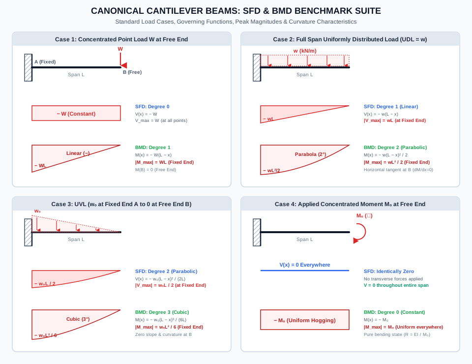
Case 1: Concentrated End Load W at Free End
Reactions at Fixed End A (x=0):VA=W(upward),MA=−WL(hogging couple)
Shear Force Equation:
At any section x (0≤x<L), looking to the right:
V(x)=−W(constant horizontal profile, Degree 0)
Bending Moment Equation:
At any section x, moment of force W to the right:
M(x)=−W(L−x)(linear profile, Degree 1)
At x=0 (Fixed End): M(0)=−WL
At x=L (Free End): M(L)=0
Case 2: Full Span Uniformly Distributed Load w
Reactions at Fixed End A (x=0):VA=wL(upward),MA=−2wL2(hogging couple)
Shear Force Equation:V(x)=−w(L−x)(linear profile, Degree 1)
At x=0: V(0)=−wL
At x=L: V(L)=0
Bending Moment Equation:M(x)=−2w(L−x)2(2nd-degree parabolic profile, Degree 2)
At x=0: M(0)=−2wL2
At x=L: M(L)=0 with horizontal tangent (dxdMx=L=V(L)=0)
Case 3: Uniformly Varying Load (UVL: w0 at Fixed Base to 0 at Free End)
Load Intensity:w(x′)=w0Lx′=w0LL−x
Total Load:Wtotal=21w0L
Reactions at Fixed End A (x=0):VA=21w0L,MA=−(21w0L)(3L)=−6w0L2
Shear Force & Moment Functions:V(x)=−2Lw0(L−x)2(2nd-degree parabola)M(x)=−6Lw0(L−x)3(3rd-degree cubic parabola)
Case 4: Applied Concentrated Couple M0 at Free End
Reactions at Fixed End A (x=0):VA=0,MA=−M0
Shear Force & Moment Functions:V(x)=0(identically zero across the entire span)M(x)=−M0(uniform constant hogging moment across the entire span, Degree 0)Note: The beam is in a state of pure bending with constant curvature κ=EIM0.
3.2 Simply Supported Beam Canonical Cases
Let the left pin support be at A (x=0) and the right roller support be at B (x=L).
        Pin A                                          Roller B
         ▲ =============================================== ▲
        / \                                               / \
         │←────────────────────── L ─────────────────────→│
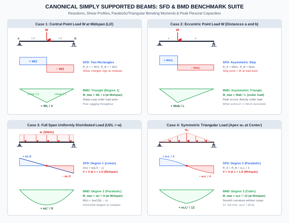
Case 1: Central Concentrated Load W at Midspan (x=L/2)
Support Reactions: By symmetry,
RA=RB=2W
Shear Force Profile:V(x)={+2W−2Wfor 0≤x<2Lfor 2L<x≤L
Step discontinuity of magnitude ΔV=−W occurs at x=L/2.
Bending Moment Profile:M(x)={2Wx2W(L−x)for 0≤x≤2Lfor 2L≤x≤L
Peak bending moment at midspan:
Mmax=2W(2L)=4WL
Case 2: Eccentric Point Load W at Distances a and b (a+b=L)
Support Reactions: Taking moments about B and A:
RA=LWb,RB=LWa
Shear Force Profile:V(x)={+LWb−LWafor 0≤x<afor a<x≤L
Bending Moment Profile:M(x)={(LWb)x(LWa)(L−x)for 0≤x≤afor a≤x≤L
Peak bending moment under the load point (x=a):
Mmax=RA⋅a=LWab
Special check: When a=b=L/2, Mmax=LW(L/2)(L/2)=4WL, recovering Case 1.
Case 3: Full Span Uniformly Distributed Load w
Support Reactions: By symmetry,
RA=RB=2wL
Shear Force Profile:V(x)=RA−wx=2wL−wx=w(2L−x)
Slopes linearly from +wL/2 at A to −wL/2 at B.
Crosses zero (V=0) at midspan: x=L/2.
Bending Moment Profile:M(x)=RAx−2wx2=2wLx−2wx2=2wx(L−x)
Maximum bending moment at x=L/2:
Mmax=2w(L/2)(L−2L)=8wL2
Curve is a 2nd-degree symmetric parabola with a horizontal tangent (dxdM=0) at midspan.
Case 4: Symmetric Triangular Load (0 at Supports to w0 at Midspan)
Total Load:Wtotal=21w0L
Support Reactions: By symmetry,
RA=RB=2Wtotal=4w0L
Shear Force Profile (Left Half 0≤x≤L/2):
Load intensity: w(x)=L2w0xV(x)=RA−∫0xL2w0udu=4w0L−Lw0x2
At x=0: V=+w0L/4
At x=L/2: V(L/2)=4w0L−Lw0(L/2)2=4w0L−4w0L=0
Bending Moment Profile (Left Half 0≤x≤L/2):M(x)=RAx−(21w(x)x)(3x)=4w0Lx−3Lw0x3
Maximum bending moment at midspan (x=L/2):
Mmax=4w0L(L/2)−3Lw0(L/2)3=8w0L2−24w0L2=(243−1)w0L2=242w0L2=12w0L2
4. Engineering Assumptions & Validity Limits
Prismatic Cross-Sections: The flexural rigidity EI is assumed constant along the beam length. (Non-prismatic haunched beams alter deflection and indeterminate distributions, though determinate SFD/BMD statically remains governed by equilibrium).
Euler-Bernoulli Hypothesis: Plane sections normal to the longitudinal neutral axis before bending remain plane and normal to the axis after bending.
Small Linear Displacements: Transverse beam deflections v(x)≪L. Slopes θ≪1 such that equilibrium can be formulated on the undeformed geometry.
Idealized Support Boundaries: Pin supports are frictionless hinges permitting unrestrained rotation; roller supports allow frictionless horizontal translation; fixed supports prevent both translation and rotation completely.
No Axial-Flexural Interaction: Axial thrust N(x)=0; column-buckling beam-column effects (P−δ) are neglected.
The following benchmark illustration compiles the four canonical cantilever beam load configurations alongside their exact shear force and bending moment diagrams, including peak values and polynomial curve degrees.
Figure 2: Canonical Simply Supported Beam Cases
The following benchmark illustration compiles the four canonical simply supported beam configurations: central point load, eccentric point load, full span UDL, and symmetric triangular load.
6. Solved Numerical Examples (Python-Verified)
Example 1: Multi-Loaded Stepped Cantilever Beam
Problem Statement:
A cantilever beam ABCD of length L=6.0 m is rigidly clamped at support A (x=0) and free at D (x=6.0 m). The beam is subjected to:
A uniformly distributed load w=15.0 kN/m over segment AB (0≤x≤2.0 m).
A downward concentrated point load P1=30.0 kN at B (x=2.0 m).
An applied clockwise concentrated moment M0=40.0 kNm at C (x=4.0 m).
A downward concentrated point load P2=20.0 kN at the free tip D (x=6.0 m).
Determine:
The reactive vertical shear force VA and fixed-end moment MA at support A.
Piecewise mathematical equations for shear force V(x) and bending moment M(x).
Numerical values of shear force and bending moment at critical sections (A,B−,B+,C−,C+,D).
         w = 15 kN/m          P_1 = 30 kN             M_0 = 40 kNm (↷)       P_2 = 20 kN
       ↓↓↓↓↓↓↓↓↓↓↓↓↓↓              ↓                         ↻                   ↓
    ┌──┐──────────────┬───────────────────────────────┬──────────────────────────┐
    │  │ Segment AB   │ B                             │ C                        │ D (Free)
    │A │   (2.0 m)    │           (2.0 m)             │         (2.0 m)          │
    └──┴──────────────┴───────────────────────────────┴──────────────────────────┘
Solution:
Step 1: Fixed-End Reactions at Support A:
Sum of all downward vertical loads:
WUDL=15.0 kN/m×2.0 m=30.0 kN(acting at x=1.0 m)VA=WUDL+P1+P2=30.0+30.0+20.0=80.0 kN(upward)
Taking moments about the fixed base A (ΣMA=0, counter-clockwise reactive moment Mreact balancing clockwise external moments):
Because Mreact exerts a counter-clockwise couple on the left face of the beam, the internal bending moment at A in the sagging-positive convention is:
Segment 3: 6.0<x≤9.0 m (Segment DB, unloaded):
At x=6.0 m, the second downward load W=40.0 kN drops the shear force:
V(6.0+)=−18.0−40.0=−58.0 kNV(x)=−58.0 kN(constant for 6.0<x<9.0 m)M(x)=174.0−58.0(x−6.0)
At x=9.0 m: M(9.0)=174.0−58.0(3.0)=174.0−174.0=0.0 kNm.
Closure at right roller support B: V(9.0+)=−58.0+RB=−58.0+58.0=0.0 kN.
Example 3: Comparative Analysis — Symmetric vs Asymmetric Triangular Load
Problem Statement:
A bridge girder of span L=6.0 m is simply supported at both ends. Compare the structural demands under two distinct triangular loading distributions, each with maximum peak intensity w0=24.0 kN/m:
Case A (Symmetric Triangular Load): Intensity is 0 at supports A and B, increasing linearly to w0=24.0 kN/m at midspan (x=3.0 m).
Case B (Full Span Asymmetric Triangular Load): Intensity is 0 at support A (x=0), increasing linearly across the entire span to w0=24.0 kN/m at support B (x=6.0 m).
Compute and compare:
The total applied load Wtotal and support reactions for both cases.
The location xmax and magnitude Mmax of the peak bending moment.
The percentage difference in maximum bending moment between Case A and Case B.
Solution:
Analysis of Case A (Symmetric Peak at Midspan):
Total Load:WA=21w0L=21(24.0)(6.0)=72.0 kN
Support Reactions:RA=RB=272.0=36.0 kN
Location of Peak Moment: By symmetry, V=0 occurs at midspan:
xmax,A=2L=3.0 m
Maximum Bending Moment:Mmax,A=12w0L2=1224.0×(6.0)2=1224.0×36.0=72.0 kNm
Analysis of Case B (Asymmetric UVL across full span):
Total Load:WB=21w0L=21(24.0)(6.0)=72.0 kN
Centroid Location: At 32L=4.0 m from A.
Support Reactions:RB=6.0WB×4.0=6.072.0×4.0=48.0 kNRA=72.0−48.0=24.0 kN
Location of Zero Shear (V(x)=0):V(x)=RA−2Lw0x2=24.0−2(6.0)24.0x2=24.0−2.0x2=0⟹x2=12.0xmax,B=3L=36.0=23 m≈3.4641 m
Maximum Bending Moment:Mmax,B=93w0L2=9324.0×(6.0)2=93864.0=396.0≈55.4256 kNm
Comparative Performance Summary:
Parameter
Case A (Symmetric UVL)
Case B (Full Span Asymmetric UVL)
Ratio (Case A / Case B)
Total Applied Load
72.0 kN
72.0 kN
1.000
Maximum Reaction
36.0 kN (at both ends)
48.0 kN (at support B)
0.750
Peak Moment Location xmax
3.000 m (Midspan)
3.464 m (L/3)
-
Maximum Bending Moment Mmax
72.000 kNm
55.426 kNm
1.299 (+29.90%)
Crucial Engineering Insight: Although both beams carry the exact same total load of 72.0 kN, concentrating load intensity toward the midspan (Case A) increases the flexural moment demand by 29.90% compared to pushing load toward the support (Case B). Structural engineers must therefore avoid placing heavy distributed equipment near center span.
7. Engineering Applications & Real-World Case Studies
Cantilever Balcony Slabs & Canopy Beams (IS 456:2000 Cl. 23.2):
Cantilever beams have an allowable basic span-to-effective-depth ratio of only 7 (compared to 20 for simply supported beams), reflecting their severe susceptibility to flexural creep deflection. Because M(x) is strictly negative (hogging), any misplacement of tension steel towards the bottom during construction leads to catastrophic collapse upon formwork removal.
Highway Bridge Precast Prestressed Concrete (PSC) Girders (IRC:112-2020):
Simply supported PSC I-girders or box-girders are standard across highway flyovers. The parabolic sagging BMD (Mmax=8wL2) perfectly matches the profile of a parabolic post-tensioned tendon cable:
e(x)=e0(1−L24x2)
The upward equivalent balancing load weq=L28Pe0 generated by tendon curvature directly neutralizes the gravity UDL bending moment.
Overhead Crane Gantry Girders (IS 800:2007 Cl. 3.4.2):
Crane wheel loads traveling over simply supported gantry girders represent eccentric point loads (W). The envelope of maximum bending moment is generated by evaluating Mmax=LWab as the trolley moves across the span, supplemented by a 25% dynamic impact factor.
Tower Crane Jibs:
A tower crane jib functions as a large-scale steel lattice cantilever. Counterweights placed on the short counter-jib create a counter-moment that reduces the high fixed-end moment MA produced by the lifted payload.
8. Comparative Analysis & Summary Matrix
Beam & Loading Condition
Reaction RA (Left)
Reaction RB (Right)
Max Shear Force ∥Vmax∥
Max Bending Moment ∥Mmax∥
Location of ∥Mmax∥
Moment Diagram Shape
Cantilever: End Point Load W
W
-
W
WL
Fixed Support (x=0)
Triangle (Degree 1, Hogging)
Cantilever: Full UDL w
wL
-
wL
2wL2
Fixed Support (x=0)
Parabola (Degree 2, Hogging)
Cantilever: UVL (w0 at base to 0)
2w0L
-
2w0L
6w0L2
Fixed Support (x=0)
Cubic (Degree 3, Hogging)
Cantilever: End Couple M0
0
-
0
M0
Uniform across span
Rectangle (Degree 0, Hogging)
SS: Central Point Load W
2W
2W
2W
4WL
Midspan (x=L/2)
Triangle (Degree 1, Sagging)
SS: Eccentric Load W (a,b)
LWb
LWa
max(LWb,LWa)
LWab
Under Load (x=a)
Asymmetric Triangle (Degree 1)
SS: Full UDL w
2wL
2wL
2wL
8wL2
Midspan (x=L/2)
Parabola (Degree 2, Sagging)
SS: Symmetric UVL (Apex w0)
4w0L
4w0L
4w0L
12w0L2
Midspan (x=L/2)
Cubic (Degree 3, Sagging)
SS: Full UVL (0 to w0)
6w0L
3w0L
3w0L
93w0L2
x=3L≈0.577L
Cubic (Degree 3, Sagging)
9. Key Takeaways & Exam-Oriented Mnemonics
The Cantilever Factor Rule: WL→2wL2→6w0L2:
Point load factor =1.
UDL factor =1/2.
UVL (peak at base) factor =1/6.
The Simply Supported Denominator Mnemonic: 4→8→12→93:
Concentrated point load at midspan: 4WL (Denominator = 4).
Asymmetric triangular load (0 to w0): 93w0L2≈15.588w0L2 (Denominator = 93).
Cantilever Fixed Base Rule: In any statically determinate cantilever under downward load, the maximum shear and maximum bending moment always occur together at the fixed end.
Zero Contraflexure in Simply Supported Beams: A simply supported beam under purely downward gravity loading contains zero internal points of contraflexure; the entire span undergoes pure sagging curvature.
10. Common Pitfalls, Traps & Misconceptions
[!WARNING]
Pitfall 1: Misplacing Reinforcement in Cantilevers
In competitive exams (and real-life construction site failures), assuming that "beams always require tension steel at the bottom" is a fatal error. A cantilever under gravity loads sags downward, stretching the top fibers. Tension reinforcement must be anchored at the top face.
[!CAUTION]
Pitfall 2: Forgetting That Shear Magnitude is Larger Near the Stiffer Support in Eccentric Loads
For an eccentric point load at distance a from A and b from B: if a<b (load closer to A), then RA=LWb>RB=LWa. The shear force is higher on the shorter shear span, but the maximum moment remains LWab.
[!NOTE]
Pitfall 3: Tangent Angle at Free End of Cantilever with UDL
In BMD for a cantilever with UDL, the parabola has a horizontal tangent (dxdM=0) at the free end B because the shear force is zero there (V(L)=0). At the fixed support A, the slope is steep and equals −wL. Drawing a horizontal tangent at the fixed base is a standard drafting error.
11. Standard Specifications & Code Provisions
Standard
Clause / Section
Engineering Requirement
IS 456:2000
Table 22 & Cl. 23.2.1
Basic span-to-effective-depth ratios for deflection control: Cantilever = 7, Simply Supported = 20, Continuous = 26 (valid for spans up to 10 m).
IS 456:2000
Cl. 22.2 (a)
Effective span of simply supported beams: smaller of (clear span+effective depth d) or (center-to-center distance of supports).
IS 456:2000
Cl. 22.2 (c)
Effective span of cantilever beams: length to the face of support plus half the effective depth d/2 (or to the center of support for continuous beams).
(GATE CE Pattern) A simply supported beam of span L=8 m carries a concentrated load W=60 kN at a distance of 2 m from the left support. Find the maximum bending moment and the shear force in the longer segment.
Answer:a=2 m,b=6 m. RA=860×6=45 kN,RB=860×2=15 kN. Maximum bending moment Mmax=LWab=860×2×6=90 kNm. Shear force in the longer segment (between load and B) is V=−RB=−15 kN.
(UPSC ESE Pattern) A cantilever beam of length L carries a UDL w over half its length starting from the fixed support (from x=0 to x=L/2). Determine the maximum bending moment at the fixed support.
Answer: The load acts over length L/2 with resultant W=w(L/2)=2wL. The centroid of this UDL is at distance 21(L/2)=4L from the fixed base. Therefore, the moment at the fixed base is MA=−W×4L=−(2wL)(4L)=−8wL2.
(SSC JE Pattern) The ratio of maximum bending moment in a simply supported beam of span L carrying a central point load W to that in a cantilever beam of length L carrying the same point load W at its free end is:
(A) 1/2
(B) 1/4
(C) 1/8
(D) 2
Answer: (B) 1/4. For simply supported beam, Mmax=4WL. For cantilever, Mmax=WL. Ratio =WLWL/4=41.