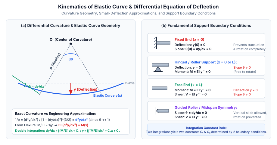
When a straight structural beam is subjected to transverse loads or bending couples, its longitudinal centroidal axis bends into a continuous, smooth plane curve called the elastic curve (or deflection curve).
Under standard Euler-Bernoulli assumptions:
Cross-sections originally perpendicular to the beam axis remain planar and perpendicular to the deformed neutral axis after bending (Bernoulli's hypothesis).
The material obeys Hooke's law linearly (E=constant).
Deformations are strictly elastic and small compared to the overall beam dimensions.
2.2 Why Deflection Governs Structural Design (Serviceability vs Strength)
In modern civil engineering practice, sizing a beam purely to resist bending stress (σ≤σallow) and shear stress (τ≤τallow) is insufficient:
Serviceability Limit State (SLS): A beam may possess abundant strength against collapse, yet fail in service due to excessive flexibility:
Aesthetic and Psychological Distress: Excessive sag creates a visible impression of impending collapse, alarming building occupants.
Non-Structural Damage: Sagging floors crack brittle partition walls, shatter plastered ceilings, and jam doors and windows.
Drainage Ponding: Severe sag on flat roofs traps rainwater, creating a dangerous progressive ponding cycle leading to roof collapse.
Machinery Misalignment: Crane gantry girders and bridge decks require stringent deflection control (e.g., span/750) to prevent crane derailment and high dynamic vibrations.
Sagging Bending Moment (+M): Centers of curvature lie above the beam (concave upwards); dx2d2y>0.
Hogging Bending Moment (−M): Centers of curvature lie below the beam (concave downwards); dx2d2y<0.
Deflection (y): Upward displacement is +y; downward displacement is −y.
5. Support Boundary Conditions
Solving the second-order differential equation requires evaluating two constants of integration (C1 and C2) using the physical constraints imposed by the supports:
  ┌──────────────────────────────┬─────────────────────────────────────────────────────────┐
  │ Support Type                 │ Boundary Conditions (at position x = a)                 │
  ├──────────────────────────────┼─────────────────────────────────────────────────────────┤
  │ Fixed Support (Built-in)     │ Deflection: y(a) = 0                                    │
  │                              │ Slope: θ(a) = dy/dx = 0                                 │
  ├──────────────────────────────┼─────────────────────────────────────────────────────────┤
  │ Pinned / Hinged Support      │ Deflection: y(a) = 0                                    │
  │                              │ Bending Moment: M(a) = EI (d²y/dx²) = 0                 │
  ├──────────────────────────────┼─────────────────────────────────────────────────────────┤
  │ Roller Support               │ Deflection: y(a) = 0                                    │
  │                              │ Bending Moment: M(a) = EI (d²y/dx²) = 0                 │
  ├──────────────────────────────┼─────────────────────────────────────────────────────────┤
  │ Free End (Cantilever Tip)    │ Bending Moment: M(a) = EI (d²y/dx²) = 0                 │
  │                              │ Shear Force: V(a) = EI (d³y/dx³) = 0                    │
  ├──────────────────────────────┼─────────────────────────────────────────────────────────┤
  │ Guided Roller (Shear Slide)  │ Slope: θ(a) = dy/dx = 0                                 │
  │                              │ Shear Force: V(a) = EI (d³y/dx³) = 0                    │
  ├──────────────────────────────┼─────────────────────────────────────────────────────────┤
  │ Line of Symmetry (Midspan)   │ Slope: θ(L/2) = dy/dx = 0                               │
  │                              │ Shear Force: V(L/2) = 0 (for symmetric load)            │
  └──────────────────────────────┴─────────────────────────────────────────────────────────┘
6. Mathematical Derivations of Canonical Load Cases
6.1 Cantilever Beam with Concentrated Load W at Free End
Consider a cantilever of length L and constant flexural rigidity EI, built-in at x=0 and carrying point load W at free tip x=L.
Bending Moment Equation:
At distance x from the fixed end (0≤x≤L):
M(x)=−W(L−x)=W(x−L)
Governing Differential Equation:EIdx2d2y=W(x−L)
First Integration (Slope Equation):EIdxdy=W(2x2−Lx)+C1
Boundary condition at fixed end: at x=0, dxdy=0:
0=W(0−0)+C1⟹C1=0
Hence, the slope equation is:
EIθ(x)=W(2x2−Lx)
Second Integration (Deflection Equation):EIy=W(6x3−2Lx2)+C2
Boundary condition at fixed end: at x=0, y=0:
0=W(0−0)+C2⟹C2=0
Hence, the elastic curve equation is:
EIy(x)=W(6x3−2Lx2)=−6Wx2(3L−x)
Values at Free End (x=L):
Maximum Slope:θmax=θB=dxdyx=L=EIW(2L2−L2)=−2EIWL2∣θmax∣=2EIWL2
Maximum Deflection:δmax=y(L)=EIW(6L3−2L3)=−3EIWL3∣δmax∣=3EIWL3
6.2 Cantilever Beam with Uniformly Distributed Load w over Entire Span
Consider a cantilever of length L carrying full UDL w (downward).
Bending Moment Equation:M(x)=−2w(L−x)2=−2w(L2−2Lx+x2)
Governing Equation:EIdx2d2y=−2w(L2−2Lx+x2)
First Integration:EIdxdy=−2w(L2x−Lx2+3x3)+C1
At x=0, dxdy=0⟹C1=0.
Second Integration:EIy=−2w(2L2x2−3Lx3+12x4)+C2
At x=0, y=0⟹C2=0.
EIy(x)=−24wx2(6L2−4Lx+x2)
Values at Free End (x=L):
Maximum Slope:θB=−2EIw(L3−L3+3L3)=−6EIwL3⟹∣θmax∣=6EIwL3
Maximum Deflection:δB=−24EIwL2(6L2−4L2+L2)=−24EIwL4(3)=−8EIwL4⟹∣δmax∣=8EIwL4
6.3 Simply Supported Beam with Concentrated Load W at Midspan
Consider a beam of span L supported at A (x=0) and B (x=L), with load W at center C (x=L/2).
Reactions by Equilibrium:RA=RB=2W
Bending Moment in Left Half (0≤x≤L/2):M(x)=RA⋅x=2Wx
Governing Differential Equation:EIdx2d2y=2Wx
First Integration:EIdxdy=4Wx2+C1
Due to structural and load symmetry, the elastic curve has a horizontal tangent at midspan:
At x=2L,dxdy=00=4W(2L)2+C1=16WL2+C1⟹C1=−16WL2
Therefore, the slope equation is:
EIdxdy=4Wx2−16WL2
Second Integration:EIy=12Wx3−16WL2x+C2
Boundary condition at support A: at x=0, y=0⟹C2=0.
Slope at Support A (x=0):θA=dxdyx=0=−16EIWL2⟹∣θA∣=∣θB∣=16EIWL2
Maximum Deflection at Midspan (x=L/2):δmax=y(2L)=48EIW(L/2)[4(2L)2−3L2]=96EIWL[L2−3L2]=−48EIWL3∣δmax∣=48EIWL3
6.4 Simply Supported Beam with Uniformly Distributed Load w over Full Span
Consider a beam of span L carrying full downward UDL w.
Reactions:RA=RB=2wL
Bending Moment Equation:M(x)=2wLx−2wx2=2w(Lx−x2)
Governing Equation:EIdx2d2y=2w(Lx−x2)
First Integration:EIdxdy=2w(2Lx2−3x3)+C1=4wLx2−6wx3+C1
By symmetry, at x=L/2, dxdy=0:
0=4wL(L/2)2−6w(L/2)3+C1=16wL3−48wL3+C1=24wL3+C1C1=−24wL3
Slope equation:
EIdxdy=4wLx2−6wx3−24wL3
Second Integration:EIy=12wLx3−24wx4−24wL3x+C2
Boundary condition at x=0, y=0⟹C2=0.
Elastic curve equation:
EIy(x)=−24wx(L3−2Lx2+x3)
Critical Values:
Slope at Supports (x=0):θA=−24EIwL3⟹∣θA∣=∣θB∣=24EIwL3
Maximum Deflection at Midspan (x=L/2):y(2L)=−24EIw(L/2)[L3−2L(2L)2+(2L)3]=−48EIwL[L3−2L3+8L3]=−48EIwL[85L3]=−384EI5wL4∣δmax∣=384EI5wL4
7. SVG Technical Diagrams & Visual Explanations
7.1 Kinematics of Elastic Curve & Curvature Geometry
The diagram below details the differential curvature relationships, radius of curvature ρ, small-deflection geometry, and support boundary conditions:
7.2 Canonical Slope and Deflection Coefficients
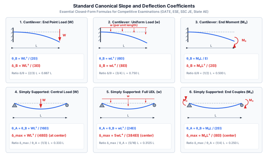
The diagram below summarizes the exact closed-form expressions for the 6 primary canonical cantilever and simply supported load cases:
8. Step-by-Step Solved Numerical Examples
Problem 1: Steel I-Beam under Combined UDL & Point Load with Serviceability Check (GATE Pattern)
Statement:
A simply supported steel floor beam of span L=6.0 m carries a uniformly distributed dead load w=20 kN/m over its entire length and a concentrated central live load W=50 kN at midspan. The beam has Young's modulus E=200 GPa (2.0×10⁵ N/mm2) and second moment of area Ixx=8.0×107 mm4.
Calculate the flexural rigidity EI in N⋅mm2 and kN⋅m2.
Compute the midspan deflection due to the UDL alone (δudl).
Compute the midspan deflection due to the point load alone (δpoint).
Determine the total midspan deflection and check if it satisfies the IS 800:2007 serviceability deflection limit (δlimit=Span/300).
Solution:
Step 1: Flexural Rigidity (EI)
EI=(2.0×10⁵ N/mm2)×(8.0×107 mm4)=1.60×10¹³ N⋅mm2
In kN⋅m2:
EI=(2.0×10⁸ kN/m2)×(8.0×10−5 m4)=16000 kN⋅m2
Step 2: Deflection due to UDL
Here w=20 kN/m=20 N/mm, L=6000 mm:
δudl=384EI5wL4=384×1.60×1013 N⋅mm25×20 N/mm×(6000 mm)4(6000)4=1.296×1015 mm4δudl=6.144×1015100×1.296×1015=6.144×10151.296×1017=21.094 mm
Step 3: Deflection due to Point Load
Here W=50 kN=50000 N:
δpoint=48EIWL3=48×1.60×1013 N⋅mm250000 N×(6000 mm)3(6000)3=2.16×1011 mm3δpoint=7.68×101450000×2.16×1011=7.68×10141.08×1016=14.062 mm
Step 4: Total Deflection & Serviceability Limit Check
By the principle of superposition:
δtotal=δudl+δpoint=21.094+14.062=35.156 mm
The permissible deflection limit according to IS 800:2007 (Table 6) for industrial buildings:
δlimit=300L=3006000 mm=20.00 mmδtotal=35.16 mm>δlimit=20.00 mm
Conclusion: The beam FAILS the serviceability deflection criterion (by +75.8%), even though it may satisfy bending stress limits. The engineer must choose a deeper section with larger Ixx.
Problem 2: Cantilever under Triangular (UVL) Load (UPSC ESE Pattern)
Statement:
A cantilever beam of span L=3.0 m is rigidly fixed at A (x=0) and carries a uniformly varying load (UVL) that is zero at the free tip B (x=L) and increases linearly to maximum intensity w0=30 kN/m at the fixed support A. Given flexural rigidity EI=1.6×10¹³ N⋅mm2, determine:
The mathematical equation for internal bending moment M(x) measuring x from the free tip.
The tip slope θB and tip deflection δB by double integration.
Solution:
Step 1: Set up Coordinate System from Free Tip
Measure coordinate z from the free end B (z=0) towards the fixed end A (z=L):
Load intensity at distance z:
w(z)=w0(Lz)
Total load on segment of length z:
W(z)=21⋅z⋅w(z)=21z(w0Lz)=2Lw0z2
Centroid of this triangular load from section z is at zˉ=z/3.
Bending moment at section z (hogging):
M(z)=−W(z)⋅3z=−(2Lw0z2)(3z)=−6Lw0z3
Slope is zero: dzdyz=L=0:
0=−24Lw0L4+C1⟹C1=24w0L3
Deflection is zero: y(L)=0:
0=−120Lw0L5+(24w0L3)L+C2=−120w0L4+24w0L4+C20=24w0L4(1−51)+C2=1204w0L4+C2=30w0L4+C2⟹C2=−30w0L4
Step 3: Values at Free Tip (z=0)
Tip Slope:θB=dzdyz=0=EIC1=24EIw0L3θB=24×(1.6×1013 N⋅mm2)(30 N/mm)×(3000 mm)3=3.84×10148.1×1011=0.00211 rad=0.121∘
Tip Deflection:δB=∣y(0)∣=EI∣C2∣=30EIw0L4δB=30×(1.6×1013 N⋅mm2)(30 N/mm)×(3000 mm)4=1.6×10¹³(3000)4=1.6×10138.1×1013=5.062 mm
Problem 3: Propped Cantilever Reaction & Maximum Deflection (State AE Pattern)
Statement:
A propped cantilever beam of span L=4.0 m is rigidly built-in at A (x=0) and supported by an unyielding roller prop at B (x=L). It carries a uniform load w=15 kN/m over its entire length. Given EI=2.0×10¹³ N⋅mm2:
Determine the prop reaction RB using deflection compatibility.
Find the fixed end moment MA.
Determine the location and magnitude of the maximum span deflection.
Solution:
Step 1: Prop Reaction via Superposition of Deflections
Treat the prop reaction RB as a redundant upward force:
Downward deflection at tip B due to UDL w on an unpropped cantilever:
δB,w=8EIwL4
Upward deflection at tip B due to upward prop reaction RB:
δB,R=3EIRBL3
Compatibility condition: The unyielding prop permits zero vertical deflection at B:
δnet=δB,w−δB,R=0⟹8EIwL4=3EIRBL3RB=83wL
Step 3: Location and Magnitude of Maximum Deflection
Measuring x from the simple prop B towards fixed end A:
M(x)=RB⋅x−2wx2=83wLx−2wx2
Integrating twice with boundary conditions y(0)=0, y(L)=0, θ(L)=0:
EIy(x)=48wx(3Lx2−2x3−L3)
Setting slope dxdy=0 yields:
6Lx−6x2−L2=0⟹6x2−6Lx+L2=0
Using the quadratic formula:
x=126±36−24L=126−12L=(63−3)L=0.421535L
For L=4000 mm:
xmax=0.421535×4000 mm=1686.14 mm from the prop
Substituting into the deflection expression yields:
δmax=EIwL4×0.005416=2.0×10¹³ N⋅mm2(15 N/mm)×(4000 mm)4×0.005416=1.040 mm
9. Comparative Analysis & Summary Matrix
Loading Case
Beam Type & Span
Maximum Slope (θmax)
Maximum Deflection (δmax)
Ratio δmax/θmax
End Point Load W
Cantilever (L)
2EIWL2 (at free tip)
3EIWL3 (at free tip)
32L≈0.667L
Full UDL w
Cantilever (L)
6EIwL3 (at free tip)
8EIwL4 (at free tip)
43L=0.750L
End Couple M0
Cantilever (L)
EIM0L (at free tip)
2EIM0L2 (at free tip)
21L=0.500L
Central Point Load W
Simply Supported (L)
16EIWL2 (at supports)
48EIWL3 (at center)
31L≈0.333L
Full UDL w
Simply Supported (L)
24EIwL3 (at supports)
384EI5wL4 (at center)
165L=0.3125L
Symmetrical Couples M0
Simply Supported (L)
2EIM0L (at supports)
8EIM0L2 (at center)
41L=0.250L
Triangular Load (0 to w0)
Cantilever (L, peak at wall)
24EIw0L3 (at free tip)
30EIw0L4 (at free tip)
54L=0.800L
Triangular Load (0 to w0)
Cantilever (L, peak at tip)
8EIw0L3 (at free tip)
120EI11w0L4 (at free tip)
1511L≈0.733L
10. Key Takeaways & Exam-Oriented Highlights
Denominators Memory Trick for Simply Supported Beams:
Central point load: θ=16EIWL2, δ=48EIWL3 (Notice 48=3×16).
Full UDL: θ=24EIwL3, δ=384EI5wL4 (Notice 384=16×24).
Denominators Memory Trick for Cantilever Beams:
Tip point load: θ=2EIWL2, δ=3EIWL3.
Full UDL: θ=6EIwL3, δ=8EIwL4.
End couple: θ=1EIML, δ=2EIML2.
Double Integration Boundary Condition Count:
Because EIdx2d2y=M(x) is a 2nd-order ODE, each integration introduces one constant, requiring strictly 2 physical boundary conditions to solve.
Propped Cantilever Fundamental Constant:
Prop reaction under UDL is always 83wL (37.5% of total load). The fixed wall takes 85wL (62.5%).
Max positive moment occurs at x=83L from prop: Mmax=1289wL2.
Max deflection occurs at x=0.4215L from prop: δmax≈185EIwL4.
11. Common Traps, Pitfalls & Counter-Intuitive Exam Scenarios
Trap 1: Applying Symmetry Condition When Load is Asymmetric: Misconception: Setting dxdyL/2=0 for a beam with an eccentric point load at L/3. Correction:dxdy=0 at midspan only if the loading and supports are perfectly symmetric. For asymmetric loads, midspan slope is non-zero, and maximum deflection shifts away from center towards the heavier load.
Trap 2: Confusing Total Load W and UDL Intensity w: Misconception: Writing 384EI5WL4 where W is total load. Correction: Total load is W=wL. In terms of total load W, the midspan deflection is 384EI5WL3.
Trap 3: Sign Confusion in Cantilever Tip Deflection: Misconception: Thinking positive y denotes downward sag. Correction: Downward displacement is mathematically −y. In descriptive questions, state either y=−8EIwL4 or "downward deflection =8EIwL4".
Trap 4: Discontinuous Moments in Double Integration: Misconception: Attempting to use a single double integration polynomial across the entire span when point loads act at interior locations. Correction: Direct double integration requires splitting the beam into segments (0≤x≤a and a≤x≤L) with 4 constants of integration, unless Macaulay's method (SOM-07-02) is employed.
12. Standard Code Provisions & Objective Practice Problems
Reference Code Clauses
IS 456:2000 Cl. 23.2 (Serviceability Deflection Limits for RCC):
Final deflection due to all loads (including shrinkage, creep, and temperature): ≤250Span.
Deflection occurring after erection of partitions and finishes: ≤350Span or 20 mm, whichever is less.
IS 800:2007 Table 6 (Deflection Limits for Steel Structures):
Purlins and girts: ≤150Span to 180Span.
Floor beams (elastic deflection under live load): ≤300Span (or 325Span for plaster ceilings).
A cantilever beam of span L and flexural rigidity EI is subjected to a concentrated couple M0 at its free end. The slope and deflection at the free end are, respectively:
(A) EIM0L and 2EIM0L2
(B) 2EIM0L and 3EIM0L2
(C) 2EIM0L2 and 3EIM0L3
(D) EIM0L and 8EIM0L2
Answer:(A) Solution: M(x)=M0⟹EIdxdy=M0x+C1. With θ(0)=0⟹C1=0⟹θB=EIM0L.
Integrating again: EIy=2M0x2+C2⟹C2=0⟹δB=2EIM0L2.
Problem 2 (UPSC ESE)
If the span of a simply supported beam carrying a uniformly distributed load over its entire length is doubled while keeping the load intensity and cross-section unchanged, the maximum deflection increases by a factor of:
(A) 4
(B) 8
(C) 16
(D) 32
Answer:(C) Solution: δmax=384EI5wL4∝L4.
If L→2L, δnew∝(2L)4=16L4. Deflection increases by a factor of 16.
Problem 3 (SSC JE / RRB JE)
A simply supported beam of span L carries a point load W at its center. The ratio of maximum deflection to maximum slope is: