Bending Stresses in Beams (04_bending_stresses_in_beams)
Difficulty Level
Intermediate to Advanced
Target Examinations
GATE CE, UPSC ESE, SSC JE, State AE/JE, RRB JE
Primary Prerequisites
Pure Bending Theory (SOM-04-01), Centroid & Moment of Inertia, Parallel Axis Theorem
Benchmark Formulas
Z=ymaxI; Log Max Strength: b=3D,d=D32⟹bd=2; Log Max Stiffness: bd=3; Diamond vs Flat: ZdiagZflat=2
Authoritative Code References
IS 800:2007 (Table 2 & Section 8), IS 456:2000, SP: 6(1)-1964
2. Physical Mechanics & Theoretical Foundation
The elastic section modulus (Z) is the fundamental geometric metric governing the flexural load-carrying capacity of a beam. Defined as the ratio of the cross-section's second moment of area (I) to the distance (ymax) from the neutral axis to the most distant extreme fiber:
Z=ymaxI
The maximum elastic bending moment (Mcapacity) that a beam can resist without exceeding the material's allowable bending stress (σallow) is directly proportional to its section modulus:
Mcapacity=σallow⋅Z
2.1 The Concept of Cross-Sectional Flexural Efficiency (η)
Not all cross-sections distribute material with equal effectiveness. Bending normal stresses vary linearly with distance from the neutral axis (σ∝y), reaching zero at the centroid. Consequently, material placed near the neutral axis contributes minimally to the moment of inertia (I=∫y2dA) while adding significant dead weight.
To quantify how efficiently a shape utilizes its cross-sectional area A to generate section modulus Z, structural mechanicians define the non-dimensional efficiency factor (η):
η=A⋅ymaxZ=A⋅ymaxI/ymax=A⋅ymax2I=(ymaxr)2
where:
r=I/A is the radius of gyration about the flexural axis.
Low Efficiency Sections (η<0.30): Diamond and solid circular sections concentrate considerable material near the neutral axis where y≈0 and taper down to narrow tips at ymax, making them inherently inefficient for uniaxial bending.
High Efficiency Sections (η≥0.50): Rolled steel I-sections, wide-flange girders, and hollow structural sections (HSS) concentrate over 70% of their area in outer flanges located at maximum distance ymax, maximizing flexural resistance per unit weight.
3. Mathematical Derivations & Governing Equations
3.1 Mathematical Formulation for Canonical Cross-Sections
Centroid Location:yˉ=3h from base; distance to apex is 32h.
Centroidal Moment of Inertia:INA=36bh3
Section Moduli:
Because the section is unsymmetrical about the neutral axis:
Ztop=ytopINA=2h/3bh3/36=24bh2(Apex fiber)Zbot=ybotINA=h/3bh3/36=12bh2(Base fiber)
Critical Ratio:
ZtopZbot=bh2/24bh2/12=2.0
Under sagging bending moments, tensile stress at the apex is twice as large as compressive stress at the base! For materials weaker in tension than compression, an upright triangle is severely disadvantaged.
6. Diamond / Square Section Bent Along Its Diagonal (Side a, Diagonal a2)
Moment of Inertia:
By rotating the coordinate axes by 45∘, the moment of inertia of a square is invariant under orthogonal rotation:
Idiag=Iflat=12a4
Extreme Fiber Distance:
Measuring to the corner tip:
ymax=2a2=2a
Section Modulus on Diagonal:Zdiag=ymaxIdiag=a/2a4/12=12/2a3=62a3≈0.11785a3
Comparison with Flat-Oriented Square Section (Zflat=6a3≈0.16667a3):ZdiagZflat=a3/(62)a3/6=2≈1.4142ZflatZdiag=21≈0.7071
The Diamond Paradox: Although both orientations possess identical cross-sectional areas (a2) and identical moments of inertia (12a4), bending a square billet along its diagonal reduces its section modulus by 29.29% because the corner tips are situated at ymax=0.707a instead of 0.500a.
3.2 Calculus Derivation: Strongest Beam Cut from a Circular Log
Consider sawing a rectangular beam of width b and depth d from a circular tree trunk of usable diameter D.
                    ┌─────── b ───────┐
                 ───┼─────────────────┼───
                ▲   │                 │
                │   │                 │
                d   │     Log Dia D   │
                │   │        /        │
                ▼   │       /         │
                 ───┼─────────────────┼───
                    └─────────────────┘
1. Geometric Constraint
From the Pythagorean theorem on the inscribed right triangle:
b2+d2=D2⟹d2=D2−b2
2. Objective Function: Maximum Flexural Strength (Section Modulus Z)
Z(b)=6bd2=6b(D2−b2)=6bD2−b3
To find the stationary point yielding maximum section modulus, differentiate Z with respect to b and set the derivative to zero:
dbdZ=6D2−3b2=0D2−3b2=0⟹b2=3D2⟹b=3D≈0.5774D
Solving for depth d:
d2=D2−b2=D2−3D2=32D2⟹d=D32≈0.8165D
3. Optimum Aspect Ratio for Strength:
bd=D/3D2/3=2≈1.4142
4. Second Derivative Concavity Verification:
db2d2Z=6−6b=−b<0
Because the second derivative is strictly negative, b=3D corresponds to a strict global maximum.
3.3 Comparative Optimizations: Strength vs Stiffness vs Area
Optimization Objective
Objective Function to Maximize
Optimal Width b
Optimal Depth d
Optimal Ratio d/b
Performance Metric
Maximum Strength
Z=6bd2
3D≈0.577D
D32≈0.816D
2≈1.414
Zmax=93D3≈0.06415D3
Maximum Stiffness
I=12bd3
2D=0.500D
D23≈0.866D
3≈1.732
Imax=323D4≈0.05413D4
Maximum Area
A=b⋅d
2D≈0.707D
2D≈0.707D
1.000 (Square)
Amax=2D2=0.5000D2
Universal Mnemonic for Inscribed Beams:
The optimal aspect ratio progresses as:
Area (d/b=1.0)⟶Strength (d/b=2)⟶Stiffness (d/b=3)
4. Engineering Assumptions & Validity Limits
Homogeneous Elastic Behavior: The cross-section consists of a single isotropic material obeying Hooke's law up to the yield stress (σ≤fy).
Symmetric Bending Axis: Bending occurs about a principal centroidal axis. If moments are applied at an inclination to the principal axes, unsymmetrical bending analysis (Mu/Iu+Mv/Iv) must be applied.
Flange and Web Slenderness (Local Buckling): For steel rolled and built-up sections, widths and thicknesses must satisfy IS 800:2007 limits (Table 2) to prevent premature local flange/web buckling before reaching the elastic section modulus Ze.
Prismatic Inscription: The cut timber beam maintains full cross-sectional rectangularity along its span without grain slope or wane exceeding IS 3629 structural timber allowances.
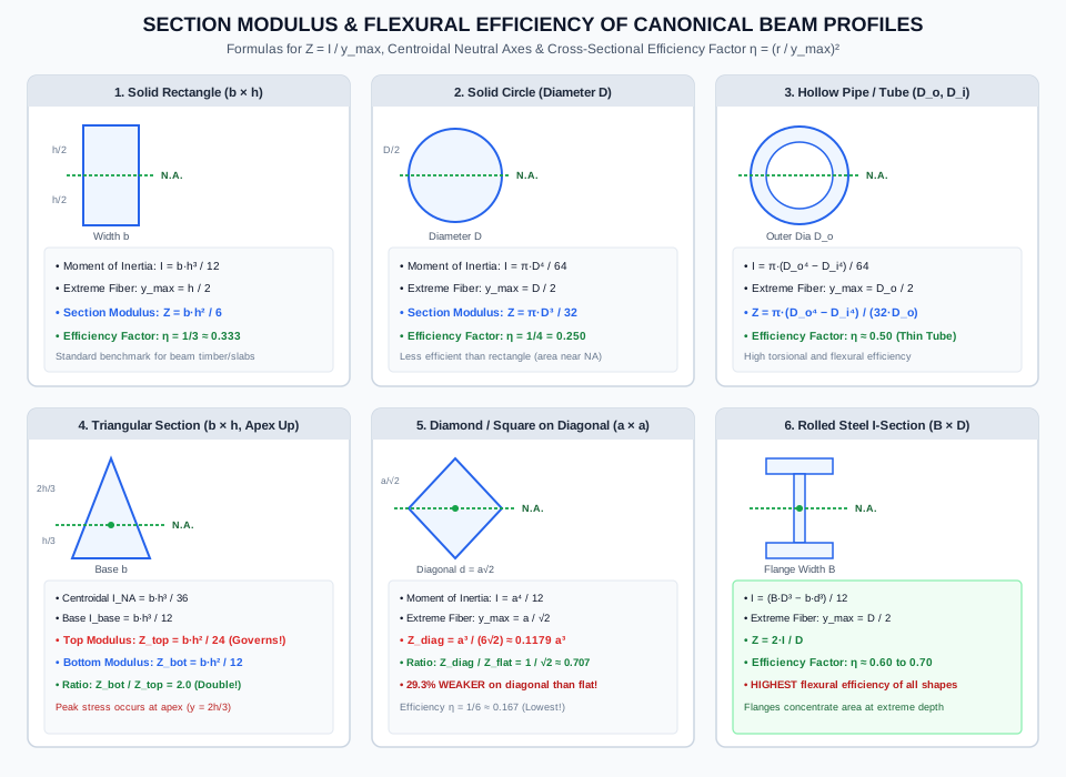
Figure 1: Section Modulus & Flexural Efficiency Across 6 Profiles
The benchmark illustration below compiles the centroidal neutral axes, section moduli Z, and cross-sectional efficiency factors η across the six canonical structural profiles.
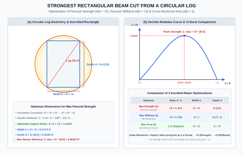
Figure 2: Strongest Beam Cut from a Circular Log
The diagram below presents the geometric constraint circle, the calculus curve Z(b) peaking at b=D/3, and the comparative performance parameters between maximum strength, stiffness, and area.
6. Solved Numerical Examples (Python-Verified)
Example 1: Timber Log Sizing — Strength vs Stiffness Tradeoff
Problem Statement:
A felled sal wood tree trunk has a circular diameter D=360.0 mm. A timber bridge contractor wishes to saw a rectangular stringer beam from this log.
The allowable bending stress for sal wood is σallow=14.0 N/mm2 and the elastic modulus is E=12.5 GPa.
Determine the cross-sectional dimensions (b and d), the section modulus Zstrength, and the allowable bending moment capacity Mstrength of the strongest beam that can be sawn from this log.
Determine the cross-sectional dimensions (b and d), the moment of inertia Istiff, and the allowable bending moment capacity Mstiff of the stiffest beam that can be sawn from this log.
Compare both beams: calculate the percentage strength advantage of the strongest beam and the percentage deflection stiffness advantage of the stiffest beam.
Solution:
Step 1: Strongest Beam (Maximizing Flexural Section Modulus Z):
Using the derived optimization formulas:
b=3D=3360.0 mm=207.8461 mmd=D32=360.0×32=360.0×0.8164966=293.9388 mm
Example 2: Flat Square vs Diamond Orientation — Quantitative Strength Degradation
Problem Statement:
A solid square structural steel billet of side dimension a=120.0 mm is used as a flexural member.
Compute the second moment of area I, extreme fiber distance ymax, section modulus Z, and efficiency factor η for:
Case A: Flat orientation (sides horizontal and vertical).
Case B: Diamond orientation (diagonal horizontal).
If both beams are subjected to a service bending moment M=25.0 kNm, calculate the maximum flexural stress induced in each orientation.
If the permissible bending stress is σallow=165.0 N/mm2, calculate the safe moment capacity of both orientations and confirm the ratio MdiagMflat=2.
Solution:
Step 1: Section Properties for Case A (Flat Orientation):
Example 3: Hollow Box Girder vs Equivalent Solid Section — Structural Efficiency
Problem Statement:
A pedestrian walkway girder is constructed as a hollow rectangular steel box of outer dimensions B=200.0 mm, H=400.0 mm and wall thickness t=12.0 mm on all four sides (b=176.0 mm,h=376.0 mm).
Calculate the cross-sectional area A, moment of inertia Ixx, section modulus Zxx, and flexural efficiency factor η of the hollow box.
Determine the dimensions Bs and Hs of an equivalent solid rectangular beam having the exact same cross-sectional area A and the same geometric aspect ratio Hs/Bs=2.0.
Calculate the section modulus Zsolid of this equivalent solid beam.
Calculate the ratio of bending moment capacities ZsolidZbox to evaluate the material efficiency of using hollow structural sections.
Centroidal Moment of Inertia:
Ixx=12BH3−bh3=12200.0×(400.0)3−176.0×(376.0)3200.0×(400.0)3=200.0×64.0×106=12,800.0×106 mm4176.0×(376.0)3=176.0×53,157,376.0=9,355.698×106 mm4Ixx=1212,800.0×106−9,355.698×106=123,444.302×106=287.025×106 mm4
Extreme Fiber Distance:
ymax=2H=2400.0=200.0 mm
Key Civil Engineering Takeaway: For the exact same steel material volume and tonnage (13,824 mm2), forming the plates into a hollow box girder increases flexural strength by 275% (3.75×) compared to a solid bar of identical proportions.
7. Engineering Applications & Real-World Case Studies
Steel Transmission Towers & Pylon Cross-Arms (IS 802):
Angle sections and built-up channels used in transmission towers are evaluated by their minimum section modulus Zvv about the minor principal axis to prevent localized overstress under lateral hurricane wind loads.
Structural Hollow Sections (SHS and RHS) in Modern Architecture (IS 4923 / IS 1161):
Architectural space trusses, airport terminal canopy cantilevers, and highway sign gantries utilize rectangular hollow sections (RHS). With an efficiency factor η≈0.52, RHS profiles offer outstanding biaxial flexural capacity combined with high closed-loop Saint-Venant torsional rigidity (J).
Optimized Formwork and Falsework Timber Joists (IRC:87-2018):
Temporary support falsework for bridge decks relies on rectangular timber joists cut from circular eucalyptus or pine logs. Civil site engineers specify sawn timber aspect ratios strictly adhering to d/b≈1.4 to extract the highest allowable design moment per cubic meter of timber purchased.
Flange Width Sizing in Plate Girders (IS 800:2007 Cl. 8.2.1):
In highway plate girders with deep thin webs, the elastic section modulus can be approximated closely by Ze≈Af⋅dw, where Af is the flange area and dw is the web depth. Flange plate thicknesses are stepped down along the span to match the decreasing moment envelope M(x).
8. Comparative Analysis & Summary Matrix
Cross-Section Type
Primary Geometry
Moment of Inertia Ixx
Section Modulus Zxx
Efficiency Factor η=(r/ymax)2
Dominant Practical Use
Solid Rectangle
b×h
12bh3
6bh2
1/3≈0.333
Timber beams, RC slabs, lintels
Solid Circle
Dia D
64πD4
32πD3
1/4=0.250
Bridge rocker pins, foundation piles, shafts
Hollow Pipe
Do,Di
64π(Do4−Di4)
32Doπ(Do4−Di4)
≈0.500
Pipeline bridges, tubular truss poles
Square (Flat)
Side a
12a4
6a3
1/3≈0.333
Machine keys, columns, billets
Square (Diamond)
Diagonal a2
12a4
62a3≈0.118a3
1/6≈0.167
Architectural columns, decorative rails
Isosceles Triangle
Base b, height h
36bh3
Ztop=24bh2,Zbot=12bh2
1/4 to 1/6
Precast inverted deck ribs
Rolled I-Beam
B×D
12BD3−bd3
D2I
0.60−0.70 (Optimal)
Primary building columns & bridge girders
9. Key Takeaways & Exam-Oriented Mnemonics
The Inscribed Log "One-Two-Three" Progression Rule:
Maximum Area: bd=1=1.0 (Square)
Maximum Strength: bd=2≈1.414 (b=D/3,d=D2/3)
Maximum Stiffness: bd=3≈1.732 (b=D/2,d=D3/2)
The "Diamond Factor" 21≈0.707:
Bending a square along its diagonal reduces Z by ≈29.3%.
Zflat=1.414Zdiag.
The Triangle Double-Modulus Rule:
In an upright triangular section (b×h): Zbot=2Ztop.
Maximum stress always occurs at the apex (ytop=2h/3).
[!WARNING]
Pitfall 1: Assuming Diamond Orientation Has a Lower Moment of Inertia
A frequent competitive exam trap states: "A square beam has lower moment of inertia along its diagonal than along its sides." This statement is FALSE. For any regular polygon (or square), the moment of inertia is strictly identical about all centroidal axes (Idiag=Iflat=a4/12). The diamond is weaker solely because its extreme fiber distance ymax=a/2 is larger than a/2!
[!CAUTION]
Pitfall 2: Confusing Strength Optimization with Stiffness Optimization
When asked for the "strongest beam cut from a log", students often inadvertently use the maximum stiffness formula (d/b=3) instead of the maximum section modulus formula (d/b=2). Remember: Strength ⟹2, Stiffness ⟹3!
[!NOTE]
Pitfall 3: Inverting Section Moduli in Triangular Cross-Sections
For an upright triangle with apex at top: ytop=2h/3 is greater than ybot=h/3. Therefore, Ztop=2h/3I=24bh2 is the smaller section modulus, not the larger one!
11. Standard Specifications & Code Provisions
Standard
Clause / Section
Engineering Requirement
IS 800:2007
Table 2 & Cl. 3.7
Limiting width-to-thickness ratios for elements of I-sections: outstanding flange width-to-thickness ratio b/tf≤9.4ϵ for Class 1 plastic, ≤10.5ϵ for Class 2 compact, and ≤15.7ϵ for Class 3 semi-compact sections (ϵ=250/fy).
IS 800:2007
Cl. 8.2.1.2
Plastic vs Elastic Section Modulus: Plastic section modulus Zp=∑Ai∣yi∣ accounts for full cross-sectional plastification, with shape factor S=Zp/Ze≈1.12−1.15 for rolled I-sections and 1.50 for solid rectangular sections.
IS 456:2000
Cl. 23.2.1
Minimum beam dimensions to avoid excessive lateral torsional buckling: unbraced length Lb≤60b or 250b2/d, whichever is less.
SP: 6(1)-1964
Section 1
Standard structural steel handbook profiles: provides tabulated values of elastic section moduli Zxx and Zyy for Indian Standard Medium Weight Beams (ISMB) and Indian Standard Wide Flange Beams (ISWB).
12. Comprehensive Formula Box & Practice Problems
Governing Formula Summary
Section Modulus: Z=ymaxI,Mallow=σallow⋅ZFlexural Efficiency Factor: η=A⋅ymaxZ=(ymaxr)2Solid Rectangle: Z=6bh2,η=31Solid Circle: Z=32πD3,η=41Hollow Circle: Z=32Doπ(Do4−Di4),η≈0.50Square Bent Flat: Zflat=6a3;Square Bent Diagonal: Zdiag=62a3=2ZflatTriangular Section (Apex Up): Ztop=24bh2,Zbot=12bh2Strongest Beam from Log: b=3D,d=D32⟹bd=2,Zmax=93D3Stiffest Beam from Log: b=2D,d=D23⟹bd=3,Imax=323D4
Practice Problems
(GATE CE Pattern) A beam of circular cross-section of diameter D is to be replaced by a rectangular beam of depth h and width b. If both beams have the same cross-sectional area and the same allowable bending stress, find the ratio of the bending strength of the rectangular beam to that of the circular beam when h=2b.
Answer: Equal area: bh=b(2b)=2b2=4πD2⟹b2=8πD2⟹b=D8π,h=2D8π. Section modulus of rectangular beam: Zr=6bh2=6b(4b2)=32b3=32(8π)3/2D3=32×162π3/2D3=242π3/2D3≈0.1641D3. Section modulus of circular beam: Zc=32πD3≈0.09817D3. Ratio: ZcZr=0.098170.1641≈1.671. The rectangular beam is ≈67.1% stronger.
(UPSC ESE Pattern) The ratio of the section modulus of a square section of side B with its sides horizontal to the section modulus of the same square section with its diagonal horizontal is: