Mohr's Circle of Plane Stress
In this chapter (5 topics)
On this page
- 1. Metadata & Syllabus Mapping
- Official Examination Syllabus Mapping
- 2. Introduction & Physical Mechanics
- Core Insights:
- 3. Mathematical Formulations & Derivations
- 3.1 Derivation of the Equation of Mohr's Circle
- 3.2 Sign Conventions for Mohr's Circle
- 3.3 Extraction of Critical Stress Values from Mohr's Circle
- 3.4 Canonical Stress States on Mohr's Circle
- 3.5 The Method of the Pole (Origin of Planes)
- 3.6 3D Triaxial Mohr's Circles & The Stress Envelope
- 4. Engineering Assumptions & Limitations
- 5. Technical Diagrams
- Diagram 1: Geometric Construction of Mohr's Circle of Stress
- Diagram 2: Canonical Stress States and 3D Mohr's Circles
- 6. Solved Numerical Examples
- Example 3.1: General 2D State of Stress & Oblique Plane Stresses
- Example 3.2: Biaxial Compression with Shear & 3D Shear Analysis
- Example 3.3: Inverse Mohr's Circle Problem (Stresses on Perpendicular Planes)
- 7. Practical & Field Engineering Applications
- 8. Comparative Analysis
- Analytical Equations vs. Mohr's Circle vs. Method of the Pole
- Canonical Stress States Summary
- 9. Key Engineering Facts & Exam Takeaways
- 10. Common Pitfalls, Traps & Anti-Patterns
- 11. Standards & Code Provisions
- IS 456:2000 (Plain and Reinforced Concrete)
- IS 800:2007 (General Construction in Steel)
- ASTM D2850 / IS 2720 (Part 10 & 12) (Soil Testing)
- 12. Comprehensive Formula Box & Practice Problems
- Master Formula Summary
- Practice Problems
1. Metadata & Syllabus Mapping
| Attribute | Specification |
|---|---|
| Topic ID | SOM-02-03 |
| Module / Subject | Subject 02: Strength of Materials (notes/strength_of_materials/) |
| Chapter | Chapter 02: Principal Stresses and Strains (02_principal_stresses_and_strains) |
| Target Examinations | GATE CE, UPSC ESE, SSC JE, RRB JE, State AE, State JE |
| Prerequisites | SOM-01-01 (Stress and Strain), SOM-02-01 (Transformation on Oblique Planes), SOM-02-02 (Principal Stresses & Max Shear) |
| Primary Code References | IS 456:2000 (Concrete Shear & Principal Stresses), IS 800:2007 (Steel Yield Criteria), ASTM D2850 (Triaxial Soil Testing) |
| Verification Gate | Level 1 through Level 7 Quality Standards |
Official Examination Syllabus Mapping
Website note: this mapping is from the author’s notes. It has not been checked against the official notification for each examination; confirm the current syllabus with the examining body.
- GATE Civil Engineering: Solid Mechanics — Transformation of plane stress; Mohr's circle of stress; principal stresses and maximum shear stress; graphical interpretation; absolute maximum shear stress; stress invariants.
- UPSC ESE (Engineering Services): Paper-I Solid Mechanics — Graphical representation of state of stress; Mohr's circle construction; pole of Mohr's circle; application to canonical stress states (pure shear, hydrostatic, uniaxial).
- SSC JE / RRB JE / State AE: Mohr's stress circle radius, center, and coordinate properties; relationship between physical plane angle θ and circle angle 2θ; radius equals maximum in-plane shear stress.
2. Introduction & Physical Mechanics
In 1882, German civil engineer Christian Otto Mohr devised an elegant, exact graphical representation of stress transformation in continuous deformable bodies.
While the analytical equations for plane stress transformation (derived in SOM-02-01) involve coupled trigonometric functions:
Mohr recognized that by eliminating the parameter , the transformation equations describe the equation of a circle in the Cartesian plane .
Core Insights:
- Duality Between Physical Element and Mohr's Circle:
- Every physical plane through a stressed point corresponds to a single point on Mohr's circle.
- Two mutually perpendicular planes in physical space (separated by ) correspond to the two diametrically opposite endpoints of a diameter on Mohr's circle (separated by ).
- Any physical rotation of angle corresponds to an angular rotation of on Mohr's circle in the same directional sense.
- Stress Invariants Visualized Geometrically:
- The center of the circle lies permanently on the normal stress axis (-axis) at coordinates . Its position is completely independent of the element's coordinate orientation.
- The radius is constant regardless of how the coordinate axes are rotated, proving that the maximum in-plane shear stress is an inherent physical property of the stress state.
- The Pole (Origin of Planes):
- A unique point on Mohr's circle that allows direct, instantaneous determination of the stresses on any plane simply by drawing a line parallel to that physical plane.
3. Mathematical Formulations & Derivations
3.1 Derivation of the Equation of Mohr's Circle
Recall the plane stress transformation relations for an oblique plane inclined at angle counterclockwise from the vertical plane:
Squaring both sides of Eq. (3.1):
Squaring both sides of Eq. (3.2):
Adding Eq. (3.3) and Eq. (3.4) directly eliminates the cross-product terms:
Using the fundamental identity :
where:
This is the standard algebraic equation of a circle:
where:
- The horizontal coordinate is normal stress: .
- The vertical coordinate is shear stress: .
- Center Coordinates: .
- Radius of Circle: .
3.2 Sign Conventions for Mohr's Circle
To ensure complete correspondence between mathematical equations and graphical constructions, the standard engineering sign convention is:
- Normal Stress ():
- Tensile stress (): Plotted to the right of the vertical -axis.
- Compressive stress (): Plotted to the left of the vertical -axis.
- Shear Stress ():
- Clockwise Shear (): Plotted upward (above the -axis). A shear stress that tends to rotate the differential element clockwise is assigned a positive vertical coordinate.
- Counterclockwise Shear (): Plotted downward (below the -axis).
- Reference Planes:
- Vertical Plane (Face ): Coordinates .
- Horizontal Plane (Face ): Coordinates .
- By complementary shear: if the shear on Face is clockwise, the shear on Face is counterclockwise. Thus, and always lie on opposite sides of the -axis!
Point X (Vertical face of element): (σ_x, τ_xy)   [Shear plotted according to rotational tendency]
Point Y (Horizontal face of element): (σ_y, -τ_xy)
The line connecting and passes directly through the center , forming the reference diameter of Mohr's circle.
3.3 Extraction of Critical Stress Values from Mohr's Circle
                             τ (Shear: CW +)
                                   |
                                   |         Top Point: τ_max = R
                                   |             (σ_avg, R)
                                   |                 ▲
                                   |              *  *  *
                                   |          *      |      *
                          X(σ_x,τ) |       *         |         *
                               \   |      *          |          *
                                \  |     *           |           *
    Minor Principal P2           \ |    *            |            *    Major Principal P1
    (σ_2, 0)                      \|   *             |             *   (σ_1, 0)
    ---|---------------------------+--*--------------+--------------*--|------------> σ
      O \                         C| (σ_avg,0)                       \
         \                         |                                  \
          \                        |                                   \
           \                       |                                    \
            \                      |                                     \
             *                     |                                      *
              *                    |                                     *
               *                   |                  *                 *
                 *                 |              *      *           *
                   *  *  *         |          *              *  *  *
                          \        |         ▼
                        Y(σ_y,-τ)  |    Bottom Point: -τ_max = -R
                                   |       (σ_avg, -R)
-
Major Principal Stress (): The rightmost intersection of the circle with the -axis ():
-
Minor Principal Stress (): The leftmost intersection of the circle with the -axis ():
-
Maximum In-Plane Shear Stress (): The highest and lowest peaks of the circle (ordinates at ):
-
Normal Stress on Maximum Shear Planes (): The abscissa of the highest/lowest points on the circle:
-
Principal Plane Orientations: The angle between the reference diameter and the principal axis is :
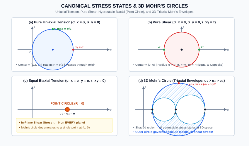
3.4 Canonical Stress States on Mohr's Circle
Mohr's circle provides rapid visual insight into standard canonical stress fields:
1. Pure Uniaxial Tension ()
- Center:
- Radius:
- Principal Stresses:
- Maximum In-Plane Shear:
- Geometrical Property: The circle touches the vertical -axis at the origin and lies entirely in the positive half-plane.
2. Pure Uniaxial Compression ()
- Center:
- Radius:
- Principal Stresses:
- Maximum In-Plane Shear:
- Geometrical Property: The circle touches the vertical -axis at the origin and lies entirely in the negative half-plane.
3. Pure Shear ()
- Center: (the origin itself!)
- Radius:
- Principal Stresses:
- Geometrical Property: The circle is centered symmetrically at the origin. The principal stresses are equal in magnitude and opposite in sign ().
4. Hydrostatic / Equal Biaxial Stress ()
- Center:
- Radius:
- Geometrical Property: The circle degenerates into a single point on the normal stress axis!
- Consequence: Every plane through the point has the identical normal stress and zero shear stress (). No in-plane shear stress can exist on any plane.
5. Equal and Opposite Biaxial Stress ()
- Center:
- Radius:
- Principal Stresses:
- Geometrical Property: Identical in geometry to pure shear rotated by . Demonstrates that equal and opposite biaxial tension/compression produces pure shear of magnitude on planes at .
3.5 The Method of the Pole (Origin of Planes)
The Pole (also called the Origin of Planes) is a unique reference point on Mohr's circle with a powerful geometric property:
The Pole Theorem:
A straight line drawn from the Pole parallel to any physical plane will intersect Mohr's circle at the point representing the state of stress acting on that physical plane.
Conversely, a straight line connecting the Pole to any stress point on the circle gives the true physical inclination of that plane!
Construction Procedure to Find the Pole:
- Locate the stress point representing the vertical plane of the element.
- From point , draw a line parallel to the plane on which those stresses act (i.e., draw a vertical line).
- The intersection of this line with Mohr's circle is the Pole ().
- (Alternatively, from point representing the horizontal plane, draw a horizontal line. It will intersect the circle at the exact same point ).
Once the Pole is found, the physical direction of the principal planes is immediately obtained by drawing straight lines from to and .
3.6 3D Triaxial Mohr's Circles & The Stress Envelope
In general three-dimensional stress analysis, every stress state is characterized by three principal stresses ordered algebraically:
The Mohr representation in 3D consists of three distinct circles plotted on the plane:
- Circle 1-2: Spanning from to , with center and radius .
- Circle 2-3: Spanning from to , with center and radius .
- Circle 1-3 (Outer Circle): Spanning from to , with center and radius .
                 τ
                 |                Outer Circle (1-3)
                 |                     *  *  *
                 |                 *      |      *
                 |              *      *  *  *      *
                 |             *   *     / \     *   *
                 |            *  *      /   \      *  *
                 |           * *       /     \       * *
                 |          **         Circle 1-2     **
                 |          *           *  *  *        *
                 |          *   *   *             *    *
                 +----------+-------+-------------+----+------------> σ
                O         σ_3     σ_2           σ_1
                           Circle 2-3
The Admissible Stress Domain:
For any arbitrarily oriented oblique plane in three-dimensional space, the normal stress and shear stress cannot fall outside the outer circle, nor can they fall inside the two inner circles.
All possible stress combinations in the body lie within the shaded annular region bounded between the three circles.
Absolute Maximum Shear Stress:
The peak of the outermost circle gives the true 3D maximum shear stress:
For a state of plane stress, . Hence:
- If and : .
- If : .
4. Engineering Assumptions & Limitations
- Infinitesimal Element Assumption: The stress tensor components represent point values across an infinitesimal continuum element where stress gradients are negligible.
- Plane Stress Formulation: Normal and shear stresses in the -direction are zero (). For thick structural walls or deep geotechnical soil masses, 3D Mohr's circles must be used.
- Linear Elastic Constitutive Response: While Mohr's circle is fundamentally a kinematic/static stress transformation tool that holds regardless of material linearity, its direct link to strains and deflections assumes Hookean behavior.
- Sign Convention Rigor: The clockwise-positive shear convention on Face is required for the angle rotation on the circle to match the physical rotation direction.
5. Technical Diagrams
Diagram 1: Geometric Construction of Mohr's Circle of Stress
The vector diagram below details the mapping from reference coordinates and to the center , the major and minor principal points , and the maximum shear stress point.
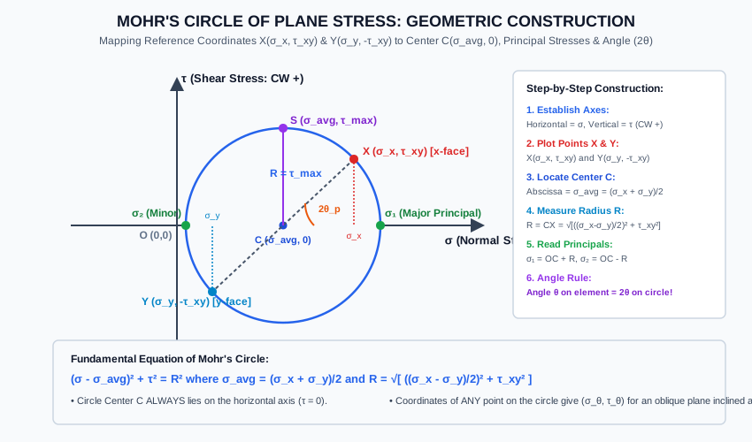
Diagram 2: Canonical Stress States and 3D Mohr's Circles
The diagram below illustrates the four fundamental canonical stress states (Uniaxial Tension, Pure Shear, Hydrostatic Point Circle) and the 3D Triaxial Mohr's Circle envelope.
6. Solved Numerical Examples
Example 3.1: General 2D State of Stress & Oblique Plane Stresses
At a critical point on the web of a plate girder, the stress components are:
- (Tension)
- (Compression)
- (Clockwise on the vertical face)
Using Mohr's circle:
- Determine the center and radius of the circle.
- Calculate the major and minor principal stresses ().
- Find the orientation of the principal planes ().
- Determine the normal and shear stresses acting on an oblique plane inclined at counterclockwise to the vertical plane.
Given:
σx = +120 MPa
σy = -20 MPa
τxy = +24 MPa
Solution:
Step 1: Compute Center Coordinates and Radius
-
Abscissa of center:
-
Half-difference of normal stresses:
-
Radius :
Step 2: Calculate Principal Stresses
- Major Principal Stress ():
- Minor Principal Stress ():
- Maximum In-Plane Shear Stress:
Check Invariant 1:
Step 3: Principal Plane Orientations
Step 4: Stresses on Oblique Plane at For point , its coordinates relative to the circle center are and (clockwise shear on the -face, plotted below the -axis in the clockwise-downward Mohr's circle convention, at angle from the -axis). Rotating counterclockwise by from radius (i.e., beyond the principal axis ), or directly via the stress transformation equations:
(Magnitude , acting counterclockwise on the plane).
Example 3.2: Biaxial Compression with Shear & 3D Shear Analysis
A soil specimen inside a triaxial testing cell is subjected to:
- (Compression)
- (Compression)
Determine:
- The center and radius of Mohr's circle.
- The principal stresses in the -plane.
- The in-plane maximum shear stress.
- The true absolute 3D maximum shear stress, assuming .
Given:
σx = -60 kPa
σy = -60 kPa
τxy = +45 kPa
σz = 0 kPa
Solution:
Step 1: Center and Radius
Step 2: Principal Stresses in the Plane
Step 3: Maximum In-Plane Shear Stress
Step 4: Absolute 3D Maximum Shear Stress The three 3D principal stresses are:
Notice that both in-plane principal stresses are compressive (same sign: and ). Therefore, the algebraically largest principal stress is , and the algebraically smallest is .
The true 3D absolute maximum shear stress is:
Key Observation: The true maximum shear stress () is greater than the in-plane maximum shear stress ()! Failing to consider the out-of-plane stress would lead to unconservative design.
Example 3.3: Inverse Mohr's Circle Problem (Stresses on Perpendicular Planes)
On two mutually perpendicular planes and passing through a point in a masonry wall, the stresses are measured as:
- Plane : (Tension), (Clockwise)
- Plane : (Tension), (Counterclockwise)
Using Mohr's circle geometry:
- Prove that line forms a diameter of the circle.
- Find the coordinates of the center and the radius .
- Determine the major and minor principal stresses.
- Calculate the stresses on a plane inclined at counterclockwise to Plane .
Given:
Point A: (90, +30)
Point B: (30, -30)
Angle between Plane A and Plane B in physical space: 90°
Solution:
Step 1: Diameter Property
In physical space, Plane and Plane are separated by .
On Mohr's circle, the angular separation is .
Therefore, points and are diametrically opposite points, and the line segment is a true diameter of the circle.
Step 2: Center Coordinates and Radius The center is the midpoint of diameter :
The radius is half the length of diameter :
Step 3: Principal Stresses
Step 4: Stresses on Plane at to Plane Rotating counterclockwise in physical space corresponds to rotating counterclockwise on Mohr's circle from point .
Relative to center , point has coordinates:
The angle of vector with the horizontal is:
Rotating counterclockwise from brings the radius vector to:
The coordinates of this new plane are:
7. Practical & Field Engineering Applications
-
Geotechnical Engineering & Mohr-Coulomb Failure Criterion:
In soil mechanics (shear strength of clays and sands), Mohr's circles are plotted from consolidated drained (CD) or undrained (CU) triaxial compression tests. The tangent line touching the failure circles across varying cell pressures () defines the Mohr-Coulomb Failure Envelope:where is soil cohesion and is the internal angle of friction.
-
Concrete Shear Design & Diagonal Tension:
Because concrete has very high compressive strength but brittle tensile strength (), Mohr's circle analysis near the supports of reinforced concrete beams demonstrates that flexural shear () and longitudinal bending () combine to produce principal tensile stresses inclined at approximately . Stirrups (shear reinforcement) are placed vertically or diagonally across these tension cracks. -
Strain Rosette Data Reduction:
In aerospace and bridge testing, electrical resistance strain rosettes measure strains along three angles (e.g., ). Mohr's circle of strain is constructed to graphically determine the principal strains () and principal directions without manual tensor mathematics. -
Underground Tunnels & In-Situ Stress Measurement:
During hydraulic fracturing or overcoring tests in rock mechanics, Mohr's circle determines whether high tectonic horizontal stresses will trigger rockbursting or roof collapse.
8. Comparative Analysis
Analytical Equations vs. Mohr's Circle vs. Method of the Pole
| Characteristic | Analytical Equations | Mohr's Stress Circle | Method of the Pole |
|---|---|---|---|
| Primary Advantage | High numerical precision, easy to code | Instant visual comprehension of all planes | Physical plane angles matched 1:1 without confusion |
| Angular Domain | Angle is | Angle is | Angle is directly parallel to physical plane |
| Principal Stresses | Calculated via quadratic square root | Extracted from circle intercepts on -axis | Intersection of rays from Pole to circle intercepts |
| Max Shear Stress | Peak of trigonometric expression | Circle radius directly | Highest point of circle directly |
| Risk of Sign Error | Moderate to High (signs in ) | Very Low (visual coordinate placement) | Lowest (pure visual ray casting) |
Canonical Stress States Summary
| Stress State | Non-Zero Stresses | Center | Radius | Major | Minor | Max In-Plane |
|---|---|---|---|---|---|---|
| Uniaxial Tension | ||||||
| Uniaxial Compression | ||||||
| Pure Shear | ||||||
| Hydrostatic Biaxial | (Point) | |||||
| Pure Biaxial Equal & Opposite |
9. Key Engineering Facts & Exam Takeaways
- Center Always on -Axis: The center of Mohr's circle always lies on the normal stress axis () because shear stress is zero when averaged across orthogonal planes ().
- Radius Equals Maximum In-Plane Shear: The radius is identically equal to the maximum in-plane shear stress .
- Point Circle (Zero Radius): A state of equal biaxial stress () produces a Mohr's circle with radius zero (a point on the -axis). Under this state, shear stress is zero on every plane in that 2D space.
- First Stress Invariant: The distance from the origin to the center of the circle is . Thus, shifting coordinate axes rotates diameter but leaves the center fixed.
- Angle Doubling (): A physical rotation of in the real element corresponds to a rotation of on Mohr's circle in the same direction.
- Complementary Shear on Circle: Points and always have equal and opposite shear ordinates, ensuring that is always a straight diameter passing through .
10. Common Pitfalls, Traps & Anti-Patterns
- Trap 1 (The Radius vs Diameter Trap): Confusing the diameter with the radius. The difference is the diameter of Mohr's circle, while is the radius.
- Trap 2 (Sign of the Center Abscissa): When one normal stress is compressive, students often write . The formula is always the algebraic average: . If and , , not .
- Trap 3 (The Same-Sign 3D Shear Blunder): Assuming the maximum shear stress is always the radius of the plane stress circle. When and have the same sign, the true maximum shear stress is , which is represented by the out-of-plane circle spanning between and .
- Trap 4 (Clockwise vs Counterclockwise Direction on Circle): Rotating the angle in the opposite direction. If the physical plane is rotated by counterclockwise, you must rotate on Mohr's circle by counterclockwise.
- Trap 5 (Shear Sign Convention Inversion): Plotting shear without checking rotational tendency. Always plot clockwise-tending shear as positive (upward) and counterclockwise as negative (downward) to preserve the rotation-direction equivalence.
11. Standards & Code Provisions
IS 456:2000 (Plain and Reinforced Concrete)
- Clause 31.6.2 & Clause 40 (Diagonal Tension & Shear):
In prestressed and reinforced concrete elements, Mohr's circle is used to calculate the principal tensile stress caused by the combination of prestress compression () and shear stress (): The cracking load is reached when exceeds the tensile strength of concrete .
IS 800:2007 (General Construction in Steel)
- Section 9 & Clause 10.5 (Combined Stresses):
Mohr's circle radius forms the basis of the Tresca maximum shear stress criterion (), which serves as a lower-bound safe design against plastic yield.
ASTM D2850 / IS 2720 (Part 10 & 12) (Soil Testing)
- Triaxial shear testing requires plotting multiple Mohr's circles at failure for varying confining pressures () to establish the strength envelope of soils.
12. Comprehensive Formula Box & Practice Problems
Master Formula Summary
Practice Problems
-
Problem 1 (GATE CE Objective):
At a point in a strained material, the state of stress is , , and . The radius of Mohr's circle is:
Answer:
Explanation: . -
Problem 2 (SSC JE Objective):
If Mohr's circle of stress for a given state of stress degenerates into a single point on the horizontal axis, the state of stress is:
Answer: Hydrostatic / Pure Biaxial equal stress ( and ).
Explanation: For radius , both and . -
Problem 3 (UPSC ESE Style):
In a state of pure shear where and normal stresses are zero, the center and radius of Mohr's circle are:
Answer: Center and Radius .
Explanation: , and . The circle is centered at the origin. -
Problem 4 (GATE CE Conceptual):
A state of plane stress has principal stresses and . The absolute maximum shear stress is:
Answer:
Explanation: Because both principal stresses are positive, . The three principal stresses are . The absolute maximum shear stress is . (Notice that in-plane shear is only ). -
Problem 5 (State AE Objective):
The coordinates of the Pole on Mohr's circle have the property that:
Answer: A straight line drawn from the Pole parallel to any physical plane intersects the circle at the stress coordinates acting on that plane.
Explanation: This is the defining kinematic property of the Pole (Origin of Planes).