SOM-04-04 Chapter 04 · Bending Stresses in Beams

Beams of Uniform Strength and Laminated Leaf Springs

1. Topic Metadata

Field Detail
Topic Identifier SOM-04-04
Subject Strength of Materials / Solid Mechanics
Chapter Bending Stresses in Beams (04_bending_stresses_in_beams)
Difficulty Level Intermediate to Advanced
Target Examinations GATE CE, UPSC ESE, SSC JE, State AE/JE, RRB JE
Primary Prerequisites Pure Bending Theory (SOM-04-01), Section Modulus (SOM-04-02), SFD and BMD (SOM-03-03)
Benchmark Formulas Beam of Uniform Strength: σmax⁡(x)=M(x)Z(x)=σallow\sigma_{\max}(x) = \frac{M(x)}{Z(x)} = \sigma_{\text{allow}}; Constant Depth: b(x)=6M(x)σallowh2b(x) = \frac{6 M(x)}{\sigma_{\text{allow}} h^2}; Constant Width: h(x)=6M(x)σallowbh(x) = \sqrt{\frac{6 M(x)}{\sigma_{\text{allow}} b}}; Leaf Spring Stress: σ=6WLnbt2\sigma = \frac{6 W L}{n b t^2}; Deflection: δ=6WL3nEbt3\delta = \frac{6 W L^3}{n E b t^3}; Nip: C=2WL3nEbt3C = \frac{2 W L^3}{n E b t^3}
Authoritative Code References IS 800:2007 (Cl. 8.2), IS 1135:1995 (Leaf Springs for Automotive Suspensions), IRS R-19 (Railway Rolling Stock Springs), SAE J510

2. Physical Mechanics & Theoretical Foundation

In conventional structural design, beams are typically manufactured with uniform (prismatic) cross-sections along their entire span. However, under non-uniform bending moments (M(x)≠constantM(x) \neq \text{constant}), the maximum permissible bending stress (σallow\sigma_{\text{allow}}) is reached at only one single critical cross-section (e.g., at the fixed root of a cantilever or at midspan of a simply supported beam). At all other sections, the induced bending stress is substantially lower than the material's allowable capacity (σ(x)≪σallow\sigma(x) \ll \sigma_{\text{allow}}).

This under-utilization represents unnecessary dead weight, higher material costs, and reduced structural efficiency—which is especially detrimental in aerospace structures, bridge cantilevers, crane booms, and automotive suspension systems.

                    PRISMATIC BEAM (Wasted Material):
         Fixed Root                                    Free Tip
        ┌──────────────────────────────────────────────────┐
        │/////// EXCESS UNUTILIZED MATERIAL ///////////////│
        ├──────────────────────────────────────────────────┤  M(x) decreases ->
        │                 Active Core                      │  σ << σ_allow
        ├──────────────────────────────────────────────────┤
        │/////// EXCESS UNUTILIZED MATERIAL ///////////////│
        └──────────────────────────────────────────────────┘

                    BEAM OF UNIFORM STRENGTH:
        Fixed Root                                    Free Tip
        \                                                 /
         \                   Tapered Profile             /
          \─────────────────────────────────────────────/
            σ_max(x) = σ_allow = CONSTANT across all x!

2.1 The Concept of Uniform Strength

A beam of uniform strength is a flexural member whose cross-sectional dimensions vary continuously along its length such that the maximum extreme fiber bending stress under a given design load is strictly equal to the allowable working stress at every single cross-section along the span:

σmax⁡(x)=M(x)Z(x)=σallow=constant for all x\sigma_{\max}(x) = \frac{M(x)}{Z(x)} = \sigma_{\text{allow}} = \text{constant for all } x   ⟹  Z(x)=M(x)σallow\implies Z(x) = \frac{M(x)}{\sigma_{\text{allow}}}

The required elastic section modulus Z(x)Z(x) at any distance xx is directly proportional to the bending moment M(x)M(x) acting at that location.


2.2 Material Savings & Structural Efficiency

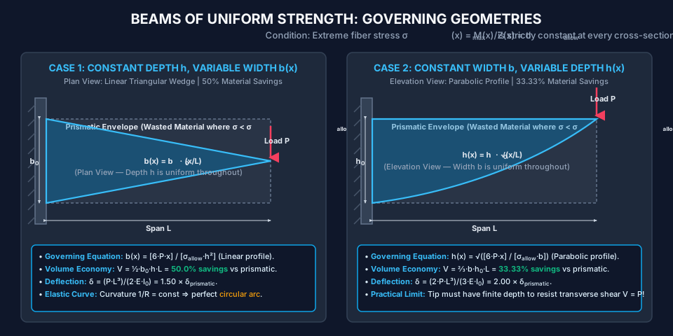
  • Constant Depth (h=consth = \text{const}), Variable Width (b(x)b(x)): For a cantilever carrying a concentrated tip load, tapering width linearly reduces beam volume and self-weight by 50.0%50.0\% compared to a prismatic beam of identical root size.
  • Constant Width (b=constb = \text{const}), Variable Depth (h(x)h(x)): Tapering depth parabolically reduces beam volume by 33.33%33.33\% (13\frac{1}{3} weight reduction).

3. Mathematical Derivations & Governing Equations

For a rectangular cross-section of width b(x)b(x) and depth h(x)h(x):

Z(x)=b(x)[h(x)]26Z(x) = \frac{b(x) [h(x)]^2}{6}

Equating this to the uniform strength requirement:

b(x)[h(x)]26=M(x)σallow\frac{b(x) [h(x)]^2}{6} = \frac{M(x)}{\sigma_{\text{allow}}}

This fundamental equation yields two primary design implementations.


3.1 Case 1: Constant Depth (h=constanth = \text{constant}), Variable Width (b(x)b(x))

When depth hh is held constant along the span, the required width profile is:

b(x)=6M(x)σallowh2b(x) = \frac{6 M(x)}{\sigma_{\text{allow}} h^2}

The width b(x)b(x) varies in direct linear proportion to the bending moment diagram M(x)M(x).

1. Cantilever with Tip Point Load PP:

Let xx be measured from the free end (0≤x≤L0 \le x \le L):

M(x)=P⋅xM(x) = P \cdot x b(x)=6Pxσallowh2=b0(xL)b(x) = \frac{6 P x}{\sigma_{\text{allow}} h^2} = b_0 \left(\frac{x}{L}\right)

where b0=6PLσallowh2b_0 = \frac{6 P L}{\sigma_{\text{allow}} h^2} is the required width at the fixed root (x=Lx = L).

  • Plan Geometry: The beam forms a symmetric triangular wedge in plan view, tapering from b0b_0 at the support to a sharp point (b=0b = 0) at the free tip.
  • Volume Economy: Vuniform=∫0Lb(x)h dx=h∫0Lb0xL dx=12b0hL=0.50⋅VprismaticV_{\text{uniform}} = \int_0^L b(x) h \, dx = h \int_0^L b_0 \frac{x}{L} \, dx = \frac{1}{2} b_0 h L = \mathbf{0.50 \cdot V_{\text{prismatic}}} Yields exactly 50.0%50.0\% material savings!

2. Deflection Analysis (Constant Depth):

From pure bending kinematics:

σmax⁡(x)=E[h/2]R(x)=σallow  ⟹  1R(x)=2σallowEh=constant\sigma_{\max}(x) = \frac{E [h/2]}{R(x)} = \sigma_{\text{allow}} \implies \frac{1}{R(x)} = \frac{2 \sigma_{\text{allow}}}{E h} = \text{constant}

Key Discovery: Because curvature 1/R1/R is constant everywhere along the span, a cantilever beam of uniform strength and constant depth bends into a perfect circular arc!

The tip deflection can be derived using the moment-area method or direct integration:

δtip=∫0L1Rx dx=2σallowEh[x22]0L=σallowL2Eh\delta_{\text{tip}} = \int_0^L \frac{1}{R} x \, dx = \frac{2 \sigma_{\text{allow}}}{E h} \left[\frac{x^2}{2}\right]_0^L = \frac{\sigma_{\text{allow}} L^2}{E h}

Substituting σallow=Mmax⁡Z0=PLb0h2/6\sigma_{\text{allow}} = \frac{M_{\max}}{Z_0} = \frac{P L}{b_0 h^2 / 6} and I0=b0h312I_0 = \frac{b_0 h^3}{12}:

δtip=PL32EI0\delta_{\text{tip}} = \frac{P L^3}{2 E I_0}

Comparing with a standard prismatic beam (δprismatic=PL33EI0\delta_{\text{prismatic}} = \frac{P L^3}{3 E I_0}):

δuniformδprismatic=1/21/3=1.50\frac{\delta_{\text{uniform}}}{\delta_{\text{prismatic}}} = \frac{1/2}{1/3} = \mathbf{1.50}

A beam of uniform strength is 50%50\% more flexible than a prismatic beam having the same root cross-section.


3.2 Case 2: Constant Width (b=constantb = \text{constant}), Variable Depth (h(x)h(x))

When width bb is held constant along the span, the required depth profile is:

h(x)=6M(x)σallowbh(x) = \sqrt{\frac{6 M(x)}{\sigma_{\text{allow}} b}}

The depth h(x)h(x) varies as the square root of the bending moment.

1. Cantilever with Tip Point Load PP:

With M(x)=PxM(x) = P x:

h(x)=6Pxσallowb=h0xLh(x) = \sqrt{\frac{6 P x}{\sigma_{\text{allow}} b}} = h_0 \sqrt{\frac{x}{L}}

where h0=6PLσallowbh_0 = \sqrt{\frac{6 P L}{\sigma_{\text{allow}} b}} is the depth at the fixed root (x=Lx = L).

  • Elevation Geometry: The profile is a parabola having a horizontal axis with its vertex located at the free end.
  • Volume Economy: Vuniform=∫0Lb⋅h(x) dx=bh0∫0LxL dx=bh0[23x3/2L1/2]0L=23bh0L=0.6667⋅VprismaticV_{\text{uniform}} = \int_0^L b \cdot h(x) \, dx = b h_0 \int_0^L \sqrt{\frac{x}{L}} \, dx = b h_0 \left[\frac{2}{3} \frac{x^{3/2}}{L^{1/2}}\right]_0^L = \frac{2}{3} b h_0 L = \mathbf{0.6667 \cdot V_{\text{prismatic}}} Yields exactly 33.33%33.33\% material savings!

2. Deflection Analysis (Constant Width):

I(x)=b[h(x)]312=bh03(x/L)3/212=I0(xL)3/2I(x) = \frac{b [h(x)]^3}{12} = \frac{b h_0^3 (x/L)^{3/2}}{12} = I_0 \left(\frac{x}{L}\right)^{3/2}

Using Castigliano's theorem or virtual work:

δtip=∫0LM(x)m(x)EI(x) dx=∫0L(Px)(x)EI0(x/L)3/2 dx=PL3/2EI0∫0Lx1/2 dx=PL3/2EI0[23x3/2]0L\delta_{\text{tip}} = \int_0^L \frac{M(x) m(x)}{E I(x)} \, dx = \int_0^L \frac{(P x)(x)}{E I_0 (x/L)^{3/2}} \, dx = \frac{P L^{3/2}}{E I_0} \int_0^L x^{1/2} \, dx = \frac{P L^{3/2}}{E I_0} \left[\frac{2}{3} x^{3/2}\right]_0^L δtip=2PL33EI0=2.00⋅δprismatic\delta_{\text{tip}} = \frac{2 P L^3}{3 E I_0} = \mathbf{2.00 \cdot \delta_{\text{prismatic}}}

A variable-depth cantilever of uniform strength deflects twice as much as an equivalent prismatic beam!


3.3 Application: Mechanics of Laminated Leaf Springs

A semi-elliptical laminated leaf spring (used extensively in automotive, railway wagon, and heavy trailer suspensions) is the direct practical realization of a beam of uniform strength.

1. Slicing and Stacking Equivalence:

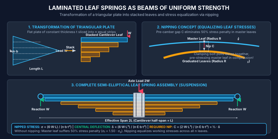
Consider a flat triangular plate of span LL, base width b0b_0, and constant thickness tt, loaded by tip force WW. As derived in Case 1, this plate is a beam of uniform strength with b(x)=b0(x/L)b(x) = b_0 (x/L). If this wide triangular plate is sliced longitudinally into nn strips of equal width b=b0/nb = b_0 / n and stacked in descending order of length, we obtain a stepped cantilever leaf spring consisting of:

  • nfn_f full-length leaves (master leaves with eye connections).
  • ngn_g graduated leaves (cut progressively shorter).
  • Total leaves: n=nf+ngn = n_f + n_g.

For a semi-elliptical spring supported at both ends over span 2L2L and loaded centrally by axle load 2W2W, each half acts as a cantilever of length LL carrying end load WW.

2. Leaf Stresses Without Nipping:

Because full-length leaves must extend to the support eyes, they bend as cantilevers over their entire length, while graduated leaves are supported by lower leaves. An un-nipped spring develops unequal stresses:

σf=18WLbt2(2ng+3nf)(Master Leaf Stress)\sigma_f = \frac{18 W L}{b t^2 (2 n_g + 3 n_f)} \quad (\text{Master Leaf Stress}) σg=12WLbt2(2ng+3nf)(Graduated Leaf Stress)\sigma_g = \frac{12 W L}{b t^2 (2 n_g + 3 n_f)} \quad (\text{Graduated Leaf Stress}) σfσg=1812=1.50\frac{\sigma_f}{\sigma_g} = \frac{18}{12} = \mathbf{1.50}

The master leaf is subjected to 50%50\% higher bending stress than the graduated leaves, leading to premature fatigue failure!

3. Stress Equalization via Nipping (Prestressing):

To overcome this stress inequality, automotive spring designers use nipping:

  • Graduated leaves are pre-bent to a smaller radius of curvature R2R_2 than the master leaves (R1R_1).
  • Before clamping, an initial gap CC (the nip) exists between the master and graduated leaves at the center.
  • Clamping the central U-bolt band draws the leaves together, inducing an initial prestress:
    • Initial compression in the top fibers of master leaves.
    • Initial tension in the top fibers of graduated leaves.
  • Under full design service load 2W2W, the initial prestress counteracts the excess bending stress in the master leaf, resulting in equalized, uniform stress across all nn leaves:
σnipped=6WLnbt2\sigma_{\text{nipped}} = \frac{6 W L}{n b t^2} δcentral=6WL3nEbt3\delta_{\text{central}} = \frac{6 W L^3}{n E b t^3} Required Initial Nip: C=2WL3nEbt3=13⋅δcentral\text{Required Initial Nip: } C = \frac{2 W L^3}{n E b t^3} = \frac{1}{3} \cdot \delta_{\text{central}} Initial Clamping Bolt Force: Pclamp=2nfngWn(2ng+3nf)\text{Initial Clamping Bolt Force: } P_{\text{clamp}} = \frac{2 n_f n_g W}{n (2 n_g + 3 n_f)}

4. Engineering Assumptions & Validity Limits

  1. Slender Euler-Bernoulli Kinematics: Standard beam theory applies (L/h≥10L/h \ge 10). Taper angles are small (≤15∘\le 15^\circ) so that the assumption of plane cross-sections remains valid.
  2. Transverse Shear Cutoff at Tip: Real beams of uniform strength cannot taper to zero dimension (b=0b=0 or h=0h=0) at the load point because the section must provide adequate shear area to resist the transverse shear force (Atip≥1.5VτallowA_{\text{tip}} \ge \frac{1.5 V}{\tau_{\text{allow}}}).
  3. Friction and Inter-Leaf Contact: In laminated leaf springs, inter-leaf friction is neglected during elastic deflection analysis, or graphite lubrication is applied between leaves.
  4. No Lateral Torsional Buckling: For beams with variable width, the slender root must satisfy IS 800:2007 lateral bracing criteria.

5. SVG Technical Illustrations & Diagrammatic Analysis

Figure 1: Beams of Uniform Strength — Governing Geometries

The diagram below illustrates the mathematical geometry of Case 1 (constant depth, linear plan wedge) and Case 2 (constant width, parabolic elevation profile) compared against prismatic envelopes.

Beams of Uniform Strength Profiles

Figure 2: Laminated Leaf Spring Mechanics & Nipping

The diagram below illustrates the conceptual transformation from a flat triangular plate of uniform strength into stacked leaves, the semi-elliptical suspension assembly, and the nip prestressing mechanics.

Laminated Leaf Spring Mechanics

6. Solved Numerical Examples (Python-Verified)

Example 1: Cantilever Beam of Uniform Strength — Linear Wedge vs Parabolic Profile

Problem Statement: A cantilever pedestrian overlook bracket of length L=2.40 mL = 2.40\text{ m} (2400.0 mm2400.0\text{ mm}) carries a downward design tip load P=15.0 kNP = 15.0\text{ kN} (15,000.0 N15,000.0\text{ N}). The allowable bending stress of the structural timber is σallow=12.0 N/mm2\sigma_{\text{allow}} = 12.0\text{ N/mm}^2.

  1. Design Case A (Constant Depth): If the depth is constant at h=250.0 mmh = 250.0\text{ mm}, calculate the required width b0b_0 at the fixed support, write the equation for b(x)b(x), and calculate the total timber volume. Compare this with a prismatic beam of cross-section b0×hb_0 \times h.
  2. Design Case B (Constant Width): If the width is constant at b=100.0 mmb = 100.0\text{ mm}, calculate the required depth h0h_0 at the fixed support, write the equation for h(x)h(x), and calculate the total timber volume. Compare this with a prismatic beam of cross-section b×h0b \times h_0.
  3. Check the required minimum dimensions at the tip (x=0x = 0) to resist transverse shear if the allowable shear stress parallel to grain is τallow=1.20 N/mm2\tau_{\text{allow}} = 1.20\text{ N/mm}^2.

Solution:

Step 1: Design Case A (Constant Depth h=250.0 mmh = 250.0\text{ mm}): Maximum bending moment occurs at the fixed root (x=L=2400.0 mmx = L = 2400.0\text{ mm}):

Mmax⁡=P×L=15,000.0 N×2400.0 mm=36.0×10⁶ N⋅mm=36.0 kNmM_{\max} = P \times L = 15,000.0\text{ N} \times 2400.0\text{ mm} = 36.0 \times 10^6\text{ N}\cdot\text{mm} = 36.0\text{ kNm}

Required section modulus at root:

Zreq=Mmax⁡σallow=36.0×10⁶ N⋅mm12.0 N/mm2=3.0×106 mm3Z_{\text{req}} = \frac{M_{\max}}{\sigma_{\text{allow}}} = \frac{36.0 \times 10^6\text{ N}\cdot\text{mm}}{12.0\text{ N/mm}^2} = 3.0 \times 10^6\text{ mm}^3

Since depth is constant (h=250.0 mmh = 250.0\text{ mm}):

Z0=b0h26  ⟹  b0=6Zreqh2=6×3.0×106(250.0)2=18.0×10662,500.0=288.0 mmZ_0 = \frac{b_0 h^2}{6} \implies b_0 = \frac{6 Z_{\text{req}}}{h^2} = \frac{6 \times 3.0 \times 10^6}{(250.0)^2} = \frac{18.0 \times 10^6}{62,500.0} = \mathbf{288.0\text{ mm}}

Width variation equation (measured from tip, 0≤x≤2400 mm0 \le x \le 2400\text{ mm}):

b(x)=b0(xL)=288.0(x2400.0)=0.120⋅x mmb(x) = b_0 \left(\frac{x}{L}\right) = 288.0 \left(\frac{x}{2400.0}\right) = \mathbf{0.120 \cdot x\text{ mm}}

Timber Volume of Case A:

VA=12b0hL=0.5×288.0 mm×250.0 mm×2400.0 mm=86.40×106 mm3=86.40 dm3 (liters)V_A = \frac{1}{2} b_0 h L = 0.5 \times 288.0\text{ mm} \times 250.0\text{ mm} \times 2400.0\text{ mm} = 86.40 \times 10^6\text{ mm}^3 = \mathbf{86.40\text{ dm}^3\text{ (liters)}}

Prismatic beam volume (288×250×2400 mm288 \times 250 \times 2400\text{ mm}):

Vprismatic,A=288.0×250.0×2400.0=172.80×106 mm3=172.80 dm3V_{\text{prismatic}, A} = 288.0 \times 250.0 \times 2400.0 = 172.80 \times 10^6\text{ mm}^3 = 172.80\text{ dm}^3 Volume Savings=172.80−86.40172.80×100%=50.0%\text{Volume Savings} = \frac{172.80 - 86.40}{172.80} \times 100\% = \mathbf{50.0\%}

Step 2: Design Case B (Constant Width b=100.0 mmb = 100.0\text{ mm}): Since width is constant (b=100.0 mmb = 100.0\text{ mm}):

Z0=bh026  ⟹  h0=6Zreqb=6×3.0×106100.0=180,000.0=424.26 mmZ_0 = \frac{b h_0^2}{6} \implies h_0 = \sqrt{\frac{6 Z_{\text{req}}}{b}} = \sqrt{\frac{6 \times 3.0 \times 10^6}{100.0}} = \sqrt{180,000.0} = \mathbf{424.26\text{ mm}}

Depth variation equation:

h(x)=h0xL=424.264x2400.0=8.6603x mmh(x) = h_0 \sqrt{\frac{x}{L}} = 424.264 \sqrt{\frac{x}{2400.0}} = \mathbf{8.6603 \sqrt{x}\text{ mm}}

Timber Volume of Case B:

VB=23bh0L=23×100.0 mm×424.264 mm×2400.0 mm=67.882×106 mm3=67.88 dm3 (liters)V_B = \frac{2}{3} b h_0 L = \frac{2}{3} \times 100.0\text{ mm} \times 424.264\text{ mm} \times 2400.0\text{ mm} = 67.882 \times 10^6\text{ mm}^3 = \mathbf{67.88\text{ dm}^3\text{ (liters)}}

Prismatic beam volume (100×424.26×2400 mm100 \times 424.26 \times 2400\text{ mm}):

Vprismatic,B=100.0×424.264×2400.0=101.823×106 mm3=101.82 dm3V_{\text{prismatic}, B} = 100.0 \times 424.264 \times 2400.0 = 101.823 \times 10^6\text{ mm}^3 = 101.82\text{ dm}^3 Volume Savings=101.823−67.882101.823×100%=33.33%\text{Volume Savings} = \frac{101.823 - 67.882}{101.823} \times 100\% = \mathbf{33.33\%}

Step 3: Transverse Shear Cutoff at Tip: At the free tip, transverse shear force is V=P=15,000.0 NV = P = 15,000.0\text{ N}. For a rectangular section, peak shear stress is τmax⁡=1.5VAtip\tau_{\max} = 1.5 \frac{V}{A_{\text{tip}}}.

Atip≥1.5Vτallow=1.5×15,000.0 N1.20 N/mm2=18,750.0 mm2A_{\text{tip}} \ge \frac{1.5 V}{\tau_{\text{allow}}} = \frac{1.5 \times 15,000.0\text{ N}}{1.20\text{ N/mm}^2} = 18,750.0\text{ mm}^2
  • For Case A (h=250 mmh = 250\text{ mm}): Minimum tip width btip=18,750.0250.0=75.0 mmb_{\text{tip}} = \frac{18,750.0}{250.0} = \mathbf{75.0\text{ mm}} (instead of 00).
  • For Case B (b=100 mmb = 100\text{ mm}): Minimum tip depth htip=18,750.0100.0=187.5 mmh_{\text{tip}} = \frac{18,750.0}{100.0} = \mathbf{187.5\text{ mm}} (instead of 00).

Example 2: Tip Deflection Comparison — Uniform Strength vs Prismatic Beam

Problem Statement: For the cantilever beam designed in Example 1, Case A (constant depth h=250.0 mmh = 250.0\text{ mm}, fixed-end width b0=288.0 mmb_0 = 288.0\text{ mm}, length L=2400.0 mmL = 2400.0\text{ mm} under load P=15.0 kNP = 15.0\text{ kN}): Given the timber Young's modulus E=11.0 GPa=11,000.0 N/mm2E = 11.0\text{ GPa} = 11,000.0\text{ N/mm}^2.

  1. Compute the tip deflection δuniform\delta_{\text{uniform}} of the beam of uniform strength.
  2. Compute the tip deflection δprismatic\delta_{\text{prismatic}} of a prismatic beam having the uniform cross-section 288.0×250.0 mm288.0 \times 250.0\text{ mm} over the entire span.
  3. Confirm the theoretical deflection ratio δuniformδprismatic=1.50\frac{\delta_{\text{uniform}}}{\delta_{\text{prismatic}}} = 1.50.

Solution:

Step 1: Tip Deflection of Beam of Uniform Strength: Root moment of inertia:

I0=b0h312=288.0×(250.0)312=288.0×15.625×10612=375.0×106 mm4I_0 = \frac{b_0 h^3}{12} = \frac{288.0 \times (250.0)^3}{12} = \frac{288.0 \times 15.625 \times 10^6}{12} = 375.0 \times 10^6\text{ mm}^4

Using the closed-form uniform strength deflection formula:

δuniform=σallowL2Eh=(12.0 N/mm2)×(2400.0 mm)2(11,000.0 N/mm2)×(250.0 mm)\delta_{\text{uniform}} = \frac{\sigma_{\text{allow}} L^2}{E h} = \frac{(12.0\text{ N/mm}^2) \times (2400.0\text{ mm})^2}{(11,000.0\text{ N/mm}^2) \times (250.0\text{ mm})} δuniform=12.0×5.76×1062,750,000.0=69.12×1062.75×106=25.1345 mm\delta_{\text{uniform}} = \frac{12.0 \times 5.76 \times 10^6}{2,750,000.0} = \frac{69.12 \times 10^6}{2.75 \times 10^6} = \mathbf{25.1345\text{ mm}}

(Verification via load formula: δ=PL32EI0=15,000.0×(2400.0)32×11,000.0×375.0×106=2.0736×10148.25×1012=25.1345 mm\delta = \frac{P L^3}{2 E I_0} = \frac{15,000.0 \times (2400.0)^3}{2 \times 11,000.0 \times 375.0 \times 10^6} = \frac{2.0736 \times 10^{14}}{8.25 \times 10^{12}} = 25.1345\text{ mm}, exact match!)

Step 2: Tip Deflection of Equivalent Prismatic Beam:

δprismatic=PL33EI0=15,000.0×(2400.0)33×11,000.0×375.0×106=2.0736×10141.2375×1013=16.7564 mm\delta_{\text{prismatic}} = \frac{P L^3}{3 E I_0} = \frac{15,000.0 \times (2400.0)^3}{3 \times 11,000.0 \times 375.0 \times 10^6} = \frac{2.0736 \times 10^{14}}{1.2375 \times 10^{13}} = \mathbf{16.7564\text{ mm}}

Step 3: Deflection Ratio:

δuniformδprismatic=25.1345 mm16.7564 mm=1.5000\frac{\delta_{\text{uniform}}}{\delta_{\text{prismatic}}} = \frac{25.1345\text{ mm}}{16.7564\text{ mm}} = \mathbf{1.5000}

Conclusion: By shaving off 50%50\% of the timber dead weight, the tip deflection increases by exactly 50%50\% (1.5×1.5\times).


Example 3: Semi-Elliptical Laminated Leaf Spring with Nipping

Problem Statement: A semi-elliptical laminated leaf spring for a railway freight wagon bogie has an effective span 2L=1000.0 mm2L = 1000.0\text{ mm} (L=500.0 mmL = 500.0\text{ mm}) and carries a central axle load 2W=10.0 kN2W = 10.0\text{ kN} (10,000.0 N10,000.0\text{ N}). The spring consists of n=10n = 10 leaves of spring steel, comprising:

  • nf=2n_f = 2 full-length master leaves.
  • ng=8n_g = 8 graduated leaves. Each leaf has width b=50.0 mmb = 50.0\text{ mm} and thickness t=10.0 mmt = 10.0\text{ mm}. Modulus of elasticity of spring steel is E=200.0 GPa=200,000.0 N/mm2E = 200.0\text{ GPa} = 200,000.0\text{ N/mm}^2.
  1. If the spring is not nipped, calculate the maximum bending stress in the master leaves (σf\sigma_f) and in the graduated leaves (σg\sigma_g).
  2. If the spring is nipped to equalize the bending stresses across all leaves, calculate the uniform working stress σnipped\sigma_{\text{nipped}} under design load 2W2W.
  3. Compute the central deflection δ\delta of the nipped spring under the 10.0 kN10.0\text{ kN} load.
  4. Determine the required initial nip CC (gap between master and graduated leaves before clamping) and the clamping bolt force PclampP_{\text{clamp}} needed to draw the leaves tight.

Solution:

Step 1: Stresses in Un-Nipped Spring: Each half of the spring carries load W=2W2=10,000.02=5,000.0 NW = \frac{2W}{2} = \frac{10,000.0}{2} = 5,000.0\text{ N}. Effective cantilever length L=500.0 mmL = 500.0\text{ mm}. Total leaves n=10n = 10, nf=2n_f = 2, ng=8n_g = 8.

Denominator term:

2ng+3nf=2(8)+3(2)=16+6=222 n_g + 3 n_f = 2(8) + 3(2) = 16 + 6 = 22

Stress in full-length master leaves:

σf=18WLbt2(2ng+3nf)=18×5,000.0×500.050.0×(10.0)2×22=45.0×1065,000.0×22=45.0×106110,000.0=409.09 N/mm2 (MPa)\sigma_f = \frac{18 W L}{b t^2 (2 n_g + 3 n_f)} = \frac{18 \times 5,000.0 \times 500.0}{50.0 \times (10.0)^2 \times 22} = \frac{45.0 \times 10^6}{5,000.0 \times 22} = \frac{45.0 \times 10^6}{110,000.0} = \mathbf{409.09\text{ N/mm}^2\text{ (MPa)}}

Stress in graduated leaves:

σg=12WLbt2(2ng+3nf)=12×5,000.0×500.0110,000.0=30.0×106110,000.0=272.73 N/mm2 (MPa)\sigma_g = \frac{12 W L}{b t^2 (2 n_g + 3 n_f)} = \frac{12 \times 5,000.0 \times 500.0}{110,000.0} = \frac{30.0 \times 10^6}{110,000.0} = \mathbf{272.73\text{ N/mm}^2\text{ (MPa)}}

Stress penalty ratio:

σfσg=409.09272.73=1.50\frac{\sigma_f}{\sigma_g} = \frac{409.09}{272.73} = \mathbf{1.50}

Without nipping, the master leaf suffers 50%50\% higher stress than the graduated leaves!

Step 2: Uniform Stress in Nipped Spring: With proper nipping, the initial prestress balances the load sharing so all n=10n = 10 leaves achieve identical stress:

σnipped=6WLnbt2=6×5,000.0 N×500.0 mm10×50.0 mm×(10.0 mm)2\sigma_{\text{nipped}} = \frac{6 W L}{n b t^2} = \frac{6 \times 5,000.0\text{ N} \times 500.0\text{ mm}}{10 \times 50.0\text{ mm} \times (10.0\text{ mm})^2} σnipped=15.0×10610×50.0×100.0=15.0×10650,000.0=300.00 N/mm2 (MPa)\sigma_{\text{nipped}} = \frac{15.0 \times 10^6}{10 \times 50.0 \times 100.0} = \frac{15.0 \times 10^6}{50,000.0} = \mathbf{300.00\text{ N/mm}^2\text{ (MPa)}}

Engineering Impact of Nipping: Nipping reduces peak stress in the master leaf from 409.09 MPa409.09\text{ MPa} down to 300.00 MPa300.00\text{ MPa}—a 26.67%26.67\% reduction in maximum stress, drastically increasing fatigue life under road vibration!

Step 3: Central Deflection of Nipped Spring:

δ=6WL3nEbt3=6×(5,000.0 N)×(500.0 mm)310×(200,000.0 N/mm2)×(50.0 mm)×(10.0 mm)3\delta = \frac{6 W L^3}{n E b t^3} = \frac{6 \times (5,000.0\text{ N}) \times (500.0\text{ mm})^3}{10 \times (200,000.0\text{ N/mm}^2) \times (50.0\text{ mm}) \times (10.0\text{ mm})^3} δ=6×5,000.0×125.0×10610×2.0×105×50.0×1,000.0=3.75×10121.0×1011=37.50 mm\delta = \frac{6 \times 5,000.0 \times 125.0 \times 10^6}{10 \times 2.0 \times 10^5 \times 50.0 \times 1,000.0} = \frac{3.75 \times 10^{12}}{1.0 \times 10^{11}} = \mathbf{37.50\text{ mm}}

Step 4: Required Initial Nip (CC) and Clamping Bolt Force (PclampP_{\text{clamp}}): Initial gap (nip) between master and graduated leaves prior to tightening the central band:

C=2WL3nEbt3=13δ=37.50 mm3=12.50 mmC = \frac{2 W L^3}{n E b t^3} = \frac{1}{3} \delta = \frac{37.50\text{ mm}}{3} = \mathbf{12.50\text{ mm}}

Clamping force required on the central U-bolt band to close the nip gap CC:

Pclamp=2nfngWn(2ng+3nf)=2×2×8×5,000.0 N10×22=160,000.0220=727.27 NP_{\text{clamp}} = \frac{2 n_f n_g W}{n (2 n_g + 3 n_f)} = \frac{2 \times 2 \times 8 \times 5,000.0\text{ N}}{10 \times 22} = \frac{160,000.0}{220} = \mathbf{727.27\text{ N}}

7. Engineering Applications & Real-World Case Studies

  1. Heavy Commercial Vehicle & Railway Bogie Leaf Springs (IS 1135 / IRS R-19): Heavy trucks, freight wagons, and locomotives rely on semi-elliptical laminated leaf springs because they function simultaneously as suspension springs and structural trailing arms, locating the axle without needing separate control links.
  2. Highway Cantilever Overhead Sign Girders & High-Mast Lighting Poles: Cantilevered highway gantry arms carrying electronic variable message signs (VMS) are fabricated with linear web-depth tapers (h(x)∝xh(x) \propto x), approaching a beam of uniform strength to minimize base overturning moments during typhoon wind gusts.
  3. Tower Crane Jibs and Mobile Telescopic Booms: The lattice and box jibs of construction tower cranes taper continuously from cab pivot to hook tip, reducing the suspended self-weight and counterweight requirements.
  4. Prestressed Concrete Variable-Depth Continuous Box Girder Bridges (IRC:112-2020): Long-span balanced cantilever concrete bridges (such as the Mahatma Gandhi Setu across the Ganges) feature parabolic haunches at pier supports, matching section depth to the high negative moment envelope M(x)M(x).

8. Comparative Analysis & Summary Matrix

Parameter Prismatic Cantilever Uniform Strength: Constant Depth (hh) Uniform Strength: Constant Width (bb) Laminated Leaf Spring
Cross-Section Variation b×h=constb \times h = \text{const} Width b(x)=b0(x/L)b(x) = b_0 (x/L) Depth h(x)=h0x/Lh(x) = h_0 \sqrt{x/L} nn stacked leaves of width bb, thick tt
Extreme Fiber Stress σ(x)\sigma(x) Linear (∝x\propto x) Constant (σallow\sigma_{\text{allow}}) Constant (σallow\sigma_{\text{allow}}) Uniform σ=6WLnbt2\sigma = \frac{6WL}{nbt^2} (if nipped)
Material Volume (VV) b0h0Lb_0 h_0 L 0.50⋅b0hL\mathbf{0.50 \cdot b_0 h L} 0.67⋅bh0L\mathbf{0.67 \cdot b h_0 L} Discrete approximation of 0.500.50
Weight Savings vs Prismatic 0%0\% (Baseline) 50.0%50.0\% Savings 33.33%33.33\% Savings ≈45−50%\approx 45 - 50\% Savings
Tip Deflection (δtip\delta_{\text{tip}}) PL33EI0\frac{P L^3}{3 E I_0} 1.50⋅δprismatic\mathbf{1.50 \cdot \delta_{\text{prismatic}}} 2.00⋅δprismatic\mathbf{2.00 \cdot \delta_{\text{prismatic}}} δ=6WL3nEbt3\delta = \frac{6 W L^3}{n E b t^3}
Elastic Curve Geometry Cubic polynomial Perfect Circular Arc Quadratic/Parabolic Arch arc (pre-cambered)

9. Key Takeaways & Exam-Oriented Mnemonics

  • The Governing Condition: σmax⁡(x)=M(x)Z(x)=σallow  ⟹  Z(x)∝M(x)\sigma_{\max}(x) = \frac{M(x)}{Z(x)} = \sigma_{\text{allow}} \implies Z(x) \propto M(x)
  • The "50-33" Volume Savings Rule:
    • Constant Depth, Linear Width   ⟹  50%\implies \mathbf{50\%} weight savings.
    • Constant Width, Parabolic Depth   ⟹  33.3%\implies \mathbf{33.3\%} (13\frac{1}{3}) weight savings.
  • The "1.5 vs 2.0" Deflection Multipliers:
    • Constant Depth   ⟹  δ=1.50×δprismatic\implies \delta = \mathbf{1.50} \times \delta_{\text{prismatic}} (Circular arc curvature 1/R=const1/R = \text{const}).
    • Constant Width   ⟹  δ=2.00×δprismatic\implies \delta = \mathbf{2.00} \times \delta_{\text{prismatic}}.
  • The Un-Nipped Spring "1.50 Stress Penalty": σmaster=1.50⋅σgraduated\sigma_{\text{master}} = 1.50 \cdot \sigma_{\text{graduated}}
  • The Nipping Rule of One-Third: Required Initial Nip C=13⋅δdesign\text{Required Initial Nip } C = \frac{1}{3} \cdot \delta_{\text{design}}

10. Common Pitfalls, Traps & Misconceptions

[!WARNING] Pitfall 1: Confusing Depth Profile with Width Profile A frequent examination trap asks for the depth variation of a cantilever point-load beam of uniform strength. Students often incorrectly answer "linear" (wedge). Linear variation applies to width (b∝xb \propto x). For depth, the relationship is parabolic: h∝xh \propto \sqrt{x}!

[!CAUTION] Pitfall 2: Neglecting Transverse Shear Failure at the Tip Mathematically, b(0)=0b(0) = 0 or h(0)=0h(0) = 0 at x=0x=0. In actual civil and mechanical practice, tapering all the way to zero thickness causes immediate punch shear failure. A minimum cross-sectional area Atip=1.5V/τallowA_{\text{tip}} = 1.5 V / \tau_{\text{allow}} must always be maintained at the load point.

[!NOTE] Pitfall 3: Inverting Full vs Cantilever Span in Leaf Springs A semi-elliptical spring of total span 2L2L loaded by 2W2W is modeled as two back-to-back cantilevers of span LL loaded by WW. Be careful not to substitute 2W2W and 2L2L directly into the single cantilever formula!


11. Standard Specifications & Code Provisions

Standard Clause / Section Engineering Requirement
IS 800:2007 Cl. 8.2 & Cl. 8.3 Tapered Structural Members: Design provisions for web-tapered I-sections in pre-engineered buildings (PEBs); requires verification that lateral torsional buckling strength is governed by the critical cross-section located at distance 0.45L0.45 L to 0.55L0.55 L from the smaller end.
IS 1135:1995 Cl. 5 & Cl. 7 Automotive Laminated Leaf Springs: Material specifications (55Si7, 60Cr4V2, 65Si7 spring steels), allowable stresses, camber tolerances (±6 mm\pm 6\text{ mm}), and fatigue life test protocols (>100,000> 100,000 full-deflection cycles).
IRS R-19 Part IV Indian Railways Rolling Stock Springs: Mandatory nipping procedures, shot peening of tension surfaces of master leaves, and eye bush clearances for broad gauge coaches and freight wagons.
SAE J510 / J1123 Section 3 Standard manual on design and application of leaf springs in commercial road transport vehicles.

12. Comprehensive Formula Box & Practice Problems

Governing Formula Summary

Beam of Uniform Strength: Z(x)=M(x)σallow\text{Beam of Uniform Strength: } Z(x) = \frac{M(x)}{\sigma_{\text{allow}}} Constant Depth Cantilever (Point Load): b(x)=6Pxσallowh2=b0xL,V=12b0hL,δ=PL32EI0\text{Constant Depth Cantilever (Point Load): } b(x) = \frac{6 P x}{\sigma_{\text{allow}} h^2} = b_0 \frac{x}{L}, \quad V = \frac{1}{2} b_0 h L, \quad \delta = \frac{P L^3}{2 E I_0} Constant Width Cantilever (Point Load): h(x)=6Pxσallowb=h0xL,V=23bh0L,δ=2PL33EI0\text{Constant Width Cantilever (Point Load): } h(x) = \sqrt{\frac{6 P x}{\sigma_{\text{allow}} b}} = h_0 \sqrt{\frac{x}{L}}, \quad V = \frac{2}{3} b h_0 L, \quad \delta = \frac{2 P L^3}{3 E I_0} Constant Depth Cantilever (UDL w): b(x)=3wx2σallowh2(Parabolic in Plan)\text{Constant Depth Cantilever (UDL } w\text{): } b(x) = \frac{3 w x^2}{\sigma_{\text{allow}} h^2} \quad (\text{Parabolic in Plan}) Constant Width Cantilever (UDL w): h(x)=x3wσallowb(Straight Wedge in Elevation)\text{Constant Width Cantilever (UDL } w\text{): } h(x) = x \sqrt{\frac{3 w}{\sigma_{\text{allow}} b}} \quad (\text{Straight Wedge in Elevation}) Un-Nipped Leaf Spring: σf=18WLbt2(2ng+3nf),σg=12WLbt2(2ng+3nf)\text{Un-Nipped Leaf Spring: } \sigma_f = \frac{18 W L}{b t^2 (2 n_g + 3 n_f)}, \quad \sigma_g = \frac{12 W L}{b t^2 (2 n_g + 3 n_f)} Nipped Leaf Spring: σ=6WLnbt2,δ=6WL3nEbt3,C=2WL3nEbt3=δ3\text{Nipped Leaf Spring: } \sigma = \frac{6 W L}{n b t^2}, \quad \delta = \frac{6 W L^3}{n E b t^3}, \quad C = \frac{2 W L^3}{n E b t^3} = \frac{\delta}{3}

Practice Problems

  1. (GATE CE Pattern) A cantilever beam of length LL carries a concentrated load PP at its free end. If the beam is designed to have uniform strength throughout its length by keeping its width constant, the depth of the beam varies:

    • (A) Linearly with xx
    • (B) Inversely with xx
    • (C) Proportional to x\sqrt{x}
    • (D) Proportional to x2x^2
    • Answer: (C) Proportional to x\sqrt{x}. Since M(x)=PxM(x) = P x, Z(x)=bh(x)26=Pxσallow  ⟹  h(x)=6Pxσallowb∝xZ(x) = \frac{b h(x)^2}{6} = \frac{P x}{\sigma_{\text{allow}}} \implies h(x) = \sqrt{\frac{6 P x}{\sigma_{\text{allow}} b}} \propto \sqrt{x}.
  2. (UPSC ESE Pattern) A cantilever beam of uniform strength with constant depth hh and fixed-end width b0b_0 has tip deflection δ1\delta_1. An otherwise identical prismatic cantilever of width b0b_0 and depth hh has tip deflection δ2\delta_2. The ratio δ1/δ2\delta_1 / \delta_2 is:

    • (A) 1.01.0
    • (B) 1.51.5
    • (C) 2.02.0
    • (D) 0.670.67
    • Answer: (B) 1.51.5. δ1=PL32EI0\delta_1 = \frac{P L^3}{2 E I_0} and δ2=PL33EI0  ⟹  δ1/δ2=1/21/3=1.50\delta_2 = \frac{P L^3}{3 E I_0} \implies \delta_1 / \delta_2 = \frac{1/2}{1/3} = 1.50.
  3. (State AE Pattern) In a laminated semi-elliptical leaf spring, "nipping" is done to:

    • (A) Increase the natural frequency of the spring
    • (B) Equalize stresses in the master leaves and graduated leaves
    • (C) Reduce friction between the leaves
    • (D) Prevent lateral buckling of the spring
    • Answer: (B) Equalize stresses in the master leaves and graduated leaves.