Shear Center in Thin-Walled Open Sections & Unsymmetrical Bending
In this chapter (3 topics)
On this page
- 1. Topic Metadata & Scope
- 2. Physical Mechanics & Theoretical Foundation
- 2.1 The Concept of Shear Center (Center of Flexure)
- 2.2 Why Thin-Walled Open Sections Are Extremely Vulnerable to Twisting
- 3. Symmetry Principles & Location Rules
- Proof of the Concurrent Intersecting Legs Theorem:
- 4. Mathematical Derivations of Shear Center
- 4.1 Thin-Walled Channel Section (Flange Width b, Web Height h, Thickness t)
- 4.2 Thin-Walled Semicircular Open Split Tube (Mean Radius R, Thickness t)
- 5. Theory of Unsymmetrical Bending
- 5.1 When Does Unsymmetrical Bending Occur?
- 5.2 Product of Inertia (Ixy)
- 5.3 Principal Axes and Principal Moments of Inertia
- 5.4 Generalized Flexural Normal Stress Formula
- 5.5 Orientation of the Neutral Axis (β)
- 6. SVG Technical Illustrations
- Figure 1: Shear Center Locations in Canonical Thin-Walled Open Sections
- Figure 2: Mechanics of Unsymmetrical Bending & Neutral Axis Deviation
- 7. Python-Recalculated Solved Numerical Examples
- Numerical Example 1: Thin-Walled Channel Section Shear Center & Shear Flows
- Numerical Example 2: Unsymmetrical Bending of an Inclined Roof Purlin
- Numerical Example 3: Split Semicircular Tube & Angle Section Accidental Torque
- 8. Practical Engineering Applications & Structural Design Considerations
- 9. Comparative Analysis & Summary Matrix
- 10. Key Takeaways & Exam-Oriented Highlights
- 11. Common Traps, Pitfalls & Counter-Intuitive Exam Scenarios
- 12. Standard Code Provisions & Objective Practice Problems
- Reference Code Clauses
- Objective Practice Problems
1. Topic Metadata & Scope
| Attribute | Specification |
|---|---|
| Topic ID | SOM-05-03 |
| Chapter | Chapter 05: Shear Stresses in Beams (05_shear_stresses) |
| Subject | Strength of Materials (Solid Mechanics) |
| Target Examinations | GATE CE, UPSC ESE, State AE |
| Prerequisites | SOM-04-01 (Flexure Formula), SOM-04-02 (Section Modulus & Principal Moments of Inertia), SOM-05-01 (Transverse Shear & Shear Flow), SOM-05-02 (Shear Stress Distribution Profiles) |
| Authoritative Reference Codes | IS 800:2007 (General Construction in Steel — Section 8 & Section 12 on Purlins and Girts), IS 801:1975 (Code of Practice for Use of Cold-Formed Light Gauge Steel Structural Members) |
| Key Terminology | Shear center (center of flexure), thin-walled open sections, shear flow line of action, concurrent intersection theorem, unsymmetrical bending, product of inertia (), principal planes of bending, neutral axis inclination () |
2. Physical Mechanics & Theoretical Foundation
2.1 The Concept of Shear Center (Center of Flexure)
In classical beam flexure theory (Euler-Bernoulli and Jourawski), it is implicitly assumed that a transverse lateral load produces pure plane bending without twisting or torsional rotation of the cross-section.
However, this assumption is physically valid if and only if the resultant transverse load passes through a unique geometric point in the cross-section known as the Shear Center (), also referred to as the Center of Flexure:
[!IMPORTANT] Definition: The Shear Center () is that unique point in the plane of a beam's cross-section through which the line of action of the transverse resultant shear force must pass such that the beam undergoes pure bending with zero torsional twisting ().
If a transverse load is applied through any point other than the shear center—for instance, through the geometric Centroid () of an asymmetric or mono-symmetric open section—the load has an eccentricity with respect to the shear center. This induces an accidental twisting couple:
2.2 Why Thin-Walled Open Sections Are Extremely Vulnerable to Twisting
Closed cross-sections (such as hollow circular tubes and rectangular box girders) possess massive torsional rigidity governed by Bredt-Batho shear flow ().
In contrast, thin-walled open sections (such as channels, angles, Z-sections, and open split tubes) enclose zero net area (). Their St. Venant torsional constant is governed solely by the sum of individual plate strips:
Because plate thickness is cubed, is orders of magnitude smaller than or (often by a factor of to ). Even a small accidental torque produces catastrophic torsional twist and lateral torsional warping, leading to premature structural collapse if the load is not applied through the shear center.
3. Symmetry Principles & Location Rules
The position of the shear center can often be determined by inspection using fundamental symmetry theorems:
+---------------------------------------------------------------------------------------+
|                              UNIVERSAL SYMMETRY THEOREMS                              |
+---------------------------------------------------------------------------------------+
| 1. TWO AXES OF SYMMETRY:                                                              |
|    If a cross-section has two mutually perpendicular axes of symmetry, the shear      |
|    center coincides EXACTLY with the centroid:                                        |
|                                       S ≡ G                                           |
|    (Examples: Symmetrical I-beam, Rectangular hollow box, Solid rectangle, Circle)    |
+---------------------------------------------------------------------------------------+
| 2. ONE AXIS OF SYMMETRY:                                                              |
|    If a cross-section has a single axis of symmetry, the shear center MUST LIE        |
|    somewhere on that axis of symmetry.                                                |
|    (Examples: Channel section [on horizontal axis], T-section [on vertical stem],     |
|     Semicircular split tube, Hat section)                                             |
+---------------------------------------------------------------------------------------+
| 3. POINT SYMMETRY (ANTISYMMETRY):                                                     |
|    If a cross-section is point-symmetric about its centroid, the shear center         |
|    coincides with the centroid:                                                       |
|                                       S ≡ G                                           |
|    (Example: Equal-flanged Z-section: S is at the center of the web)                  |
+---------------------------------------------------------------------------------------+
| 4. CONCURRENT INTERSECTING LEGS THEOREM:                                              |
|    For thin-walled open sections composed of two or more narrow straight legs whose   |
|    centerlines intersect at a single concurrent point, the shear center is located    |
|    EXACTLY at that intersection point.                                                |
|    (Examples: Angle section [corner junction], T-section [flange-stem intersection],   |
|     Cruciform cross [+] section [center of cross])                                    |
+---------------------------------------------------------------------------------------+
Proof of the Concurrent Intersecting Legs Theorem:
Consider an angle section (L-shape) or T-section composed of thin legs of thickness .
- In any thin rectangular leg of an open section, the shear flow must run parallel to the leg's centerline; the transverse shear component perpendicular to the plate thickness is negligible.
- The resultant shear force in each leg is the integral of this shear flow: , which acts strictly along the leg's centerline.
- Because the centerlines of all legs intersect concurrently at a single common junction point , the moment arm of every internal leg shear force about point is identically zero:
- Since the internal resisting shear forces generate zero moment about point , an applied external load passing through produces zero twisting moment:
- Therefore, the shear center coincides exactly with the junction of the leg centerlines!
4. Mathematical Derivations of Shear Center
4.1 Thin-Walled Channel Section (Flange Width , Web Height , Thickness )
Consider a thin-walled channel section with horizontal top and bottom flanges of width , vertical web of height , and uniform wall thickness ().
         |<--------- b --------->|
      +--+-----------------------+  ^
      |  |-------> q_f(s)           |
      |  +-----------------------+  |
      |  |                          |
      |  |                          |
   S  |  |           G              h
   •  |  | - - - - - • - - - - - -  |
      |  |           (Centroid)     |
      |  |                          |
      |  +-----------------------+  |
      |  |<------- q_f(s)           |
      +--+-----------------------+  v
      |<-e->|
Step 1: Second Moment of Area About Horizontal Centroidal Axis
The horizontal axis passing through the mid-height of the web is an axis of symmetry. The second moment of area about this neutral axis:
Step 2: Shear Flow in the Top Flange
Let be the coordinate measured along the top flange starting from the outer free edge () moving toward the web junction (). The area of the flange segment from to is . Its centroid is at distance from the neutral axis. The first moment of area of this segment:
The horizontal shear flow in the top flange is:
The total horizontal shear force in the top flange is obtained by integrating from to :
Step 3: Shear Flow in the Bottom Flange
By antisymmetry of the shear flow direction, the bottom flange carries an equal horizontal force directed in the opposite direction (from the web outward towards the free edge):
Step 4: Vertical Shear Force in the Web
The vertical shear flow in the web integrates to the total vertical applied shear force:
Step 5: Moment Equilibrium About the Web Centerline
The two horizontal flange forces are separated by the vertical distance (the web height). They form an internal couple:
This internal couple tends to twist the section counter-clockwise. For the external vertical load to produce zero twisting, it must be applied at a distance to the left of the web centerline such that its clockwise moment balances the internal couple:
Dividing both sides by :
Substituting :
Dividing numerator and denominator by :
Limiting Cases:
- Square Channel ():
- Deep Narrow Channel (, i.e., ):
- Shallow Wide Channel (, i.e., ):
[!NOTE] The shear center of a channel section lies completely outside the physical cross-section, on the side of the web opposite to the flanges!
4.2 Thin-Walled Semicircular Open Split Tube (Mean Radius , Thickness )
Consider a thin semicircular tube of mean radius and wall thickness open along one vertical diameter. Let be the circumferential angle measured from the horizontal axis of symmetry ().
- Area moment of inertia about the horizontal axis of symmetry:
- First moment of area of a circumferential segment from angle to :
- Circumferential shear flow:
- Moment of this circumferential shear flow about the center of curvature : Every element of shear flow acts tangentially at distance from the center of curvature . Therefore:
- For equilibrium without twisting, an external load applied at distance from center must satisfy:
The shear center lies on the axis of symmetry at a distance:
Because the tube radius is , the shear center lies outside the outer boundary of the tube by a distance of .
5. Theory of Unsymmetrical Bending
5.1 When Does Unsymmetrical Bending Occur?
Unsymmetrical (or biaxial) bending occurs under either of two physical conditions:
- The beam cross-section is asymmetrical (lacks axes of symmetry, e.g., unequal angle sections, Z-purlins).
- The plane of the applied bending moment does not coincide with either of the two principal centroidal axes of inertia of the cross-section.
Under unsymmetrical bending, the classical 1D flexure formula fails because the neutral axis rotates, and the beam deflects in a direction different from the plane of the applied load.
5.2 Product of Inertia ()
The product of inertia of a cross-section with respect to centroidal axes and is defined as:
Properties of :
- Unlike and (which are strictly positive), can be positive, negative, or zero.
- Symmetry Rule: If either the -axis or the -axis is an axis of symmetry, then for every area element at , there is an identical element at or . Consequently:
- For sections lacking symmetry (such as unequal angles or Z-sections), .
5.3 Principal Axes and Principal Moments of Inertia
The Principal Axes of Inertia (denoted and ) are the unique pair of orthogonal centroidal axes about which the product of inertia vanishes:
The inclination of the principal axes with respect to the reference axes is given by Mohr's circle of inertia:
The corresponding Principal Moments of Inertia are:
5.4 Generalized Flexural Normal Stress Formula
Once the principal axes and principal moments of inertia are established, any applied bending moment vector inclined at angle to the major principal axis is decomposed into components:
By the principle of superposition, the total longitudinal normal stress at any point in the cross-section is:
5.5 Orientation of the Neutral Axis ()
The Neutral Axis (N-A) is the line across the cross-section where the flexural normal stress is identically zero ():
Solving for the slope of the neutral axis :
Let be the angle that the neutral axis makes with the major principal axis ():
[!IMPORTANT] The Neutral Axis Paradox in Unsymmetrical Bending:
If the section had equal principal moments of inertia (, like a square or circle), then , meaning the neutral axis would be strictly perpendicular to the moment plane.
However, in structural beams, (often to ). Therefore, , which forces the neutral axis to swing heavily toward the minor principal axis . The neutral axis is NEVER perpendicular to the plane of the applied bending moment!
6. SVG Technical Illustrations
Figure 1: Shear Center Locations in Canonical Thin-Walled Open Sections
The diagram below illustrates the exact location of the shear center relative to the centroid and the internal shear flow mechanisms for a Channel Section, Angle Section, T-Section, and Semicircular Split Tube.
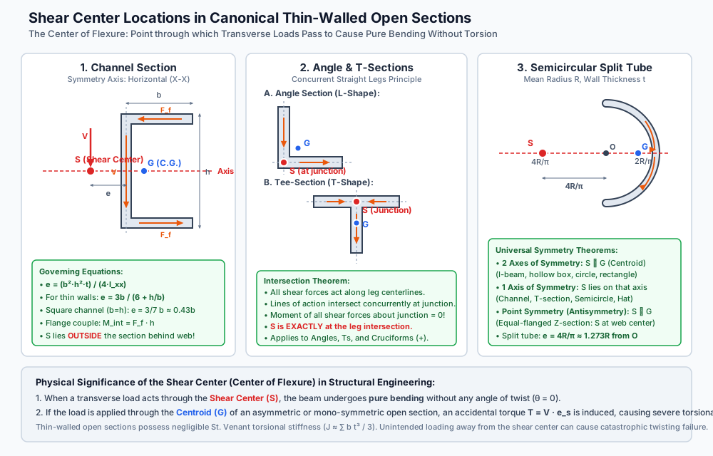
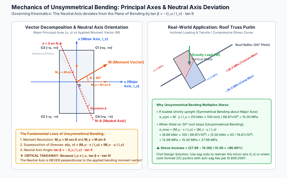
Figure 2: Mechanics of Unsymmetrical Bending & Neutral Axis Deviation
The diagram below demonstrates the vector resolution of bending moments along principal axes , the angular deviation of the neutral axis, and the resulting stress multiplication on an inclined roof purlin.
7. Python-Recalculated Solved Numerical Examples
Numerical Example 1: Thin-Walled Channel Section Shear Center & Shear Flows
Problem Statement:
A thin-walled channel section has web height , flange width , and uniform wall thickness . The section carries a vertical transverse shear force .
Calculate:
- The second moment of area about the horizontal axis of symmetry.
- The distance of the shear center from the web centerline.
- The maximum shear flow and maximum shear stress in the flanges (at the junction with the web).
- The total horizontal shear force carried by each flange.
- The maximum shear flow and maximum shear stress in the web at the neutral axis.
- Verify moment equilibrium of internal shear forces with the external load about the web midpoint.
Step-by-Step Solution:
-
Second Moment of Area :
-
Location of Shear Center :
Alternatively, using the simplified formula:
The shear center is located to the left of the web centerline (outside the channel).
-
Flange Shear Flow and Shear Stress at Junction: At the junction (), the first moment of area of the flange:
-
Total Horizontal Flange Force : Since varies linearly from at the free edge to at the web:
-
Maximum Web Shear Flow and Stress at Neutral Axis:
-
Verification of Moment Equilibrium: Internal couple produced by the two horizontal flange forces:
External moment produced by load applied through shear center:
Numerical Example 2: Unsymmetrical Bending of an Inclined Roof Purlin
Problem Statement:
A wooden roof purlin of rectangular cross-section is placed on a roof truss inclined at an angle to the horizontal. The gravity roof loads produce a vertical bending moment in the vertical plane.
Determine:
- The components of bending moment and about the principal axes of the purlin ( parallel to the side, parallel to the side).
- The inclination of the neutral axis relative to the major principal axis .
- The flexural normal stresses at each of the four corners ().
- The maximum tensile and compressive bending stresses.
- The percentage increase in maximum stress compared to pure symmetrical bending about the major axis.
Step-by-Step Solution:
-
Section Properties & Moment Decomposition:
Because the purlin is tilted by on the rafter, the vertical gravity moment vector makes an angle with the -axis:
-
Neutral Axis Inclination ():
(Note: The neutral axis is inclined at to the -axis. The normal to the moment vector is at [or ]. The neutral axis has deviated by toward the weak axis .)
-
Corner Stresses: Using the coordinates:
- (Top-Right):
- (Bottom-Left):
- (Top-Left):
- (Bottom-Right):
-
Maximum Stresses:
- Maximum tensile stress: at corner .
- Maximum compressive stress: at corner .
-
Comparison with Symmetrical Bending: If the beam had been placed upright (symmetrical bending):
Stress increase factor:
Numerical Example 3: Split Semicircular Tube & Angle Section Accidental Torque
Problem Statement:
- A thin-walled semicircular split tube has a mean radius and wall thickness . Calculate the distance of its shear center from the center of curvature .
- An equal angle section ISA carries a vertical load . The centroid of the angle is located at from the outer heel. If the load is applied directly through the centroid , calculate the accidental twisting torque induced in the member.
Step-by-Step Solution:
Part A: Semicircular Split Tube
Using the derived formula:
Distance outside the tube boundary:
Part B: Angle Section Accidental Torque
- Shear Center Location of Angle Section: By the Concurrent Intersecting Legs Theorem, the shear center of an angle section is located at the intersection of the two leg centerlines. Outer heel coordinates are . The leg centerlines are at distance from the outer edges:
- Centroid Coordinates:
- Eccentricity Between Centroid and Shear Center:
- Accidental Twisting Torque: When the vertical load is applied through centroid , its horizontal distance from the shear center is : A severe torque of is developed, which will cause massive torsional twisting of the thin angle strut unless torsional restraints are provided!
8. Practical Engineering Applications & Structural Design Considerations
- Light-Gauge Cold-Formed Steel Purlins (IS 800:2007 Cl. 8.9 & IS 801:1975): Cold-formed C-channels and Z-purlins are standard in pre-engineered industrial buildings (PEBs). Because roofs slope at , purlins undergo unsymmetrical bending. To prevent excessive lateral deflection along the weak axis (), structural engineers install sag rods (tie rods) at mid-span or third-points connecting purlins to the apex ridge purlin.
- Crane Gantry Girders: Gantry girders carry vertical wheel loads from the overhead crane as well as horizontal surge/lateral forces from crane braking. Because the horizontal surge force acts on the top flange while vertical loads act downwards, gantry girders undergo severe unsymmetrical bending and torsion. To resist this, a channel section is welded horizontally to the top flange of an I-beam to dramatically increase and relocate the shear center upward.
- Purlin Orientation on Sloping Roofs: Cold-formed Z-sections are preferred over C-channels for continuous purlins because the top flange can be oriented facing up the roof slope, creating a component of bending that opposes gravity-induced lateral drift.
9. Comparative Analysis & Summary Matrix
| Section Type | Symmetry Class | Centroid Location () | Shear Center Location () | Does ? | Accidental Torque if Loaded at ? |
|---|---|---|---|---|---|
| Symmetrical I-Beam | Double Symmetry | Geometric Center | Geometric Center | YES () | None () |
| Hollow Rectangular Box | Double Symmetry | Geometric Center | Geometric Center | YES () | None () |
| Equal-Flanged Z-Section | Point Symmetry | Web Midpoint | Web Midpoint | YES () | None () |
| Channel Section | Single Symmetry | Inside channel cavity | Outside web () | NO | Severe () |
| Angle Section (L-Shape) | Single / Asymmetry | Interior of corner | Corner junction of leg centerlines | NO | Severe () |
| Tee-Section (T-Shape) | Single Symmetry | On stem below flange | Junction of flange and web centerlines | NO | Moderate (on stem axis) |
| Cruciform Section (+) | Double Symmetry | Intersection of legs | Intersection of legs | YES () | None () |
| Split Semicircular Tube | Single Symmetry | from center | from center (Outside tube) | NO | Extreme () |
10. Key Takeaways & Exam-Oriented Highlights
- Definition of Shear Center: The point in the cross-section through which transverse shear loads must pass to produce pure bending without any twisting.
- Channel Section Formula: The shear center of a channel section lies outside the web on the horizontal symmetry axis.
- Semicircular Split Tube Formula:
- Concurrent Intersection Theorem: For angles, T-sections, and cruciforms, the shear center is located exactly at the intersection of the leg centerlines.
- Double Symmetry & Point Symmetry:
- If a section has 2 axes of symmetry .
- If a section has point symmetry (equal Z-section) .
- Unsymmetrical Bending Normal Stress:
- Neutral Axis Inclination in Unsymmetrical Bending: The neutral axis is never perpendicular to the moment plane when .
11. Common Traps, Pitfalls & Counter-Intuitive Exam Scenarios
- Trap 1: Assuming Shear Center Always Lies Within the Cross-Section Material:
Misconception: Believing must be a physical point on the beam material.
Correction: For channel sections, hat sections, and split semicircular tubes, lies in empty space outside the cross-section boundary! - Trap 2: Assuming for Channel Sections:
Misconception: Applying loads through the centroid of a channel beam.
Correction: Loading through induces a large twisting torque , causing severe twisting. - Trap 3: Believing the Neutral Axis is Perpendicular to the Applied Load in Purlins:
Misconception: Calculating roof purlin bending assuming 1D deflection perpendicular to the roof rafter.
Correction: Due to the factor , the neutral axis rotates heavily, increasing bending stresses by to . - Trap 4: Forgetting the Web Centerline Reference for Channel :
Misconception: Measuring from the outer face or centroid instead of the web centerline.
Correction: In standard formula derivations, is measured from the centerline of the web.
12. Standard Code Provisions & Objective Practice Problems
Reference Code Clauses
- IS 800:2007 (Cl. 8.9): Design of members subject to combined bending and torsion must satisfy , and torsional warping stresses must be superposed onto flexural stresses.
- IS 800:2007 (Cl. 12.3.2): Purlins subjected to inclined loads on sloping roofs should be designed considering biaxial bending, or provided with sag rods to restrain lateral deflection along the weak axis.
- IS 801:1975 (Cl. 6.4): Open light gauge steel members must be loaded through the shear center or provided with lateral bracing to prevent lateral torsional buckling.
Objective Practice Problems
Problem 1 (GATE CE)
A thin-walled channel section of flange width , web depth , and uniform wall thickness has its shear center located at distance from the web centerline. If the flange width is doubled while web depth and thickness remain unchanged, the value of :
- (A) Doubles
- (B) Quadruples
- (C) Increases by a factor of
- (D) Decreases
Answer: (C)
Solution: . When : .
Problem 2 (UPSC ESE)
The shear center of an equal angle section ISA is located at:
- (A) The centroid of the section
- (B) The intersection of the centerlines of the two legs
- (C) The outer corner (heel) of the angle
- (D) Mid-length of each leg
Answer: (B)
Solution: By the concurrent intersecting legs theorem, the shear flows in both legs act along their centerlines and intersect concurrently at the junction of the centerlines. Therefore, the internal shear forces exert zero moment about this junction, making it the shear center.
Problem 3 (GATE CE / State AE)
For a thin-walled semicircular split tube of mean radius , the shear center is located on the axis of symmetry at a distance from the center of curvature equal to:
- (A)
- (B)
- (C)
- (D)
Answer: (C)
Solution: measured from the center of curvature . (Note: is the location of the centroid, not the shear center).
Problem 4 (ESE / State AE)
In unsymmetrical bending of a beam, the neutral axis:
- (A) Always passes through the shear center and is perpendicular to the bending moment vector
- (B) Passes through the centroid and is perpendicular to the bending moment vector
- (C) Passes through the centroid but is NOT generally perpendicular to the bending moment vector
- (D) Coincides with the minor principal axis
Answer: (C)
Solution: In unsymmetrical bending, . Because , , meaning the neutral axis is not perpendicular to the bending moment vector.
Problem 5 (GATE CE)
A rectangular beam with is subjected to a bending moment inclined at to the major principal axis . The angle made by the neutral axis with the -axis is:
- (A)
- (B)
- (C)
- (D)
Answer: (C)
Solution: .
.