Anchor Bolts, Holding Down Bolts & Shear Keys
In this chapter (3 topics)
On this page
- 1. Topic Metadata & Syllabus Mapping
- 2. Executive Summary & Core Engineering Concepts
- 3. Comprehensive Technical Principles & Mechanics
- 3.1 Eccentricity Regimes in Base Plates
- 3.2 Limit State Equilibrium under Large Eccentricity (e > L/6)
- 3.3 Anchor Bolt Failure Modes & Embedment Mechanics
- 3.4 Horizontal Shear Transfer Mechanisms
- 4. Detailed Technical Diagrams & Visual Models
- 4.1 Moment-Resisting Base Plate Stress Block and Anchor Bolt Mechanics
- 4.2 Anchor Bolt Embedment Failure Modes & Welded Shear Lug Detailing
- 5. Comprehensive Step-by-Step Mathematical Derivations & Code Clauses
- 5.1 Derivation of Compression Depth xu & Bolt Tension T
- 5.2 Combined Tension & Shear Interaction (IS 800:2007 Cl. 10.3.6)
- 5.3 Welded Shear Lug Design Formulation
- 6. Three Fully Worked Unit-Checked Numerical Examples
- Example 1: Moment-Resisting Base Plate with Large Uplift Eccentricity
- Example 2: Heavy Lateral Shear Lug Design
- Example 3: Anchor Bolt Combined Tension & Shear Interaction Check
- 7. Common Engineering Pitfalls & Examination Traps
- 8. Real-World Failure Case Studies & Forensic Analysis
- Forensic Investigation: Braced Industrial Mill Building Erection Collapse
- 9. Competitive Examination Practice Problems
- Problem 1 (GATE CE - 2 Marks)
- Problem 2 (UPSC ESE Paper-I - 2 Marks)
- Problem 3 (SSC JE - 1 Mark)
- Problem 4 (State PSC AE - 2 Marks)
- Problem 5 (RRB JE - 1 Mark)
- 10. Cross-Subject Synthesis & Advanced Structural Connections
- 11. Standard Reference Textbooks & Official Code Specifications
- 12. Comprehensive Summary, Formula Cheatsheet & Key Takeaways
1. Topic Metadata & Syllabus Mapping
| Attribute | Specification |
|---|---|
| Module / Topic ID | STEEL-07-03 |
| Subject | Design of Steel Structures (IS 800:2007) |
| Chapter | 07: Column Bases and Foundations |
| Topic Title | Anchor Bolts, Holding Down Bolts & Shear Keys |
| Primary Reference Standards | IS 800:2007 (Cl. 7.4, Cl. 10.3, Cl. 10.4), IS 456:2000 (Cl. 34.4), AISC Design Guide 1 (Base Plate and Anchor Rod Design), ACI 318 Annex D / Chapter 17 (Anchoring to Concrete) |
| Target Competitive Examinations | GATE CE, UPSC ESE (Paper-I), SSC JE, State PSC AE/JE, RRB JE |
| Examination Weightage | GATE (1 to 2 Marks), UPSC ESE (12 to 20 Marks subjective / 2 to 4 Marks prelims), State AE/JE (2 to 4 Marks) |
| Prerequisites | STEEL-07-01 (Slab Bases), STEEL-07-02 (Gusseted Bases), SOM-03-01 (Combined Bending & Direct Stress) |
2. Executive Summary & Core Engineering Concepts
In industrial buildings, tall cantilever columns, portal frame eaves, wind towers, and mill buildings, column bases are subjected not merely to concentric gravity thrust (), but simultaneously to large overturning moments () and substantial horizontal lateral shears () generated by wind, seismic, crane braking, and portal action.
When the eccentricity of the resultant axial force exceeds the kern limit of the base plate ( in a rectangular base of length ), the base plate undergoes tensile separation (uplift) along the windward edge. Under limit state design principles:
- Moment-Resisting Base Action: Concrete cannot sustain tension across the steel-concrete interface. Consequently, a triangular compressive bearing stress block develops under the leeward edge (), while tension is mobilized exclusively by steel anchor bolts (holding-down bolts) anchored deep into the reinforced concrete pedestal or footing.
- Anchor Bolt Mechanics: Anchor bolts resist net uplift (), pullout, concrete breakout cone failure, and shear slippage. Bolt diameter and embedment depth must satisfy direct tension resistance (), ductile yield before brittle concrete failure, and combined shear-tension interaction per IS 800:2007 Cl. 10.3.6.
- Horizontal Shear Transfer Mechanics: Lateral shear is resisted through three distinct mechanisms in order of structural efficiency:
- Interfacial Friction: ( between grout/plate). Applicable only under persistent compressive load without uplift.
- Anchor Bolt Dowel Action: Involves bending and shear in the bolts across the grout layer, prone to bolt hole slop (oversized anchor holes) and grout crushing unless welded washer plates are deployed.
- Welded Shear Lugs (Shear Keys): For heavy shear (), solid rectangular steel blocks or structural I/T-sections are shop-welded beneath the base plate and grouted into keyways recessed into the concrete pedestal. Bearing against hardened concrete () bypasses the anchor bolts entirely, safeguarding them against low-cycle fatigue and cyclic shear failure.
3. Comprehensive Technical Principles & Mechanics
3.1 Eccentricity Regimes in Base Plates
Let a column base plate have length (along the moment plane) and width (transverse). Subjected to axial load and bending moment , the eccentricity is:
+-----------------------------------------------------------------------------------+
| Regimes of Base Plate Loading:                                                    |
| 1. e <= L/6: Small Eccentricity (Full Contact)                                    |
|    - Trapezoidal bearing stress: w_max, w_min >= 0                                |
|    - No uplift; anchor bolts carry nominal installation tension only.             |
|                                                                                   |
| 2. e = L/6: Kern Boundary                                                         |
|    - Triangular bearing stress: w_max = 2P / (B*L), w_min = 0                     |
|    - Lift-off is impending along windward edge.                                   |
|                                                                                   |
| 3. e > L/6: Large Eccentricity (Partial Contact / Uplift Regime)                  |
|    - Tensile separation occurs on windward side.                                  |
|    - Concrete bearing block is triangular over contact length x_u.                |
|    - Anchor bolts on windward side carry direct factored tensile force T.         |
+-----------------------------------------------------------------------------------+
3.2 Limit State Equilibrium under Large Eccentricity ()
Let the anchor bolts on the tension side be positioned at an effective distance from the compressive extreme edge of the base plate (edge distance to bolts = ).
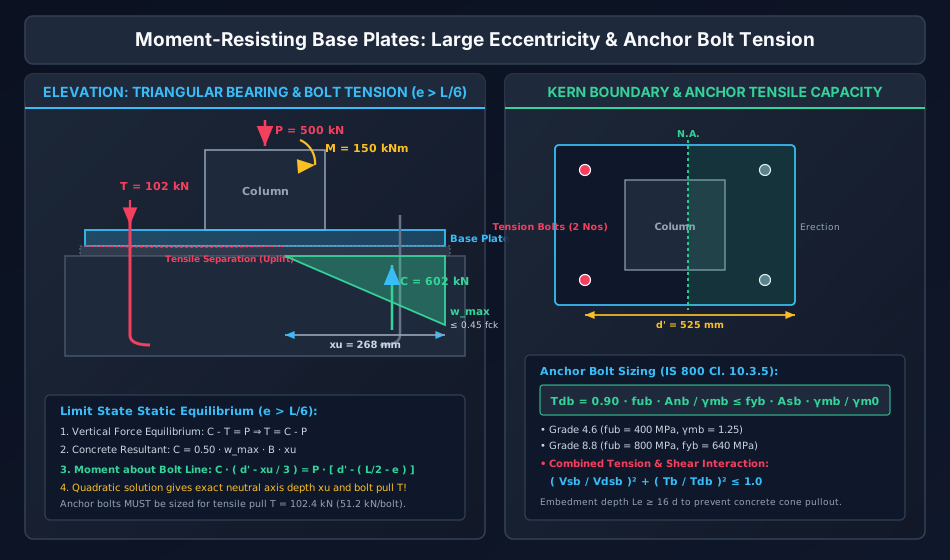
- Concrete compressive bearing stress reaches its limit state capacity: .
- Length of triangular compression zone = .
- Total concrete compressive force: acting at centroidal distance from the extreme compressive edge.
- Anchor bolt tension acts at distance from the compressive edge.
- Axial column load acts at column centerline, located at distance from the edge. Its actual line of action is offset by eccentricity toward the compression edge. Thus, distance of from the compression edge is .
Moment Equilibrium about the Anchor Bolt Line:
Taking moments about the center of tension bolts ( has zero lever arm):
Substitute :
This yields a quadratic equation in :
Solving the quadratic equation gives the contact length . Once is determined:
Vertical Force Equilibrium:
If bolts are provided on the tension side, tension per bolt is:
3.3 Anchor Bolt Failure Modes & Embedment Mechanics
Anchor bolts embedded in concrete can fail in six distinct failure mechanisms (ACI 318-19 Ch. 17 / IS 800:2007 Cl. 10.3 / IS 456 Cl. 26.2):
                   CONCRETE PEDESTAL ANCHORAGE

           Base Plate [=======|=======] Grout Pad (25 mm)
                              |
       +----------------------|----------------------+
       |                      |                      |
       |  \   Concrete Cone   |  Breakout Cone   /   |
       |   \  Failure (35°)   |                 /    |
       |    \                 |                /     |
       |     \                |               /      |
       |      \               |              /       |
       |       \              |             /        |
       |        +-------------O------------+         |
       |                   Anchor Nut                |
       |                   & End Plate               |
       +---------------------------------------------+
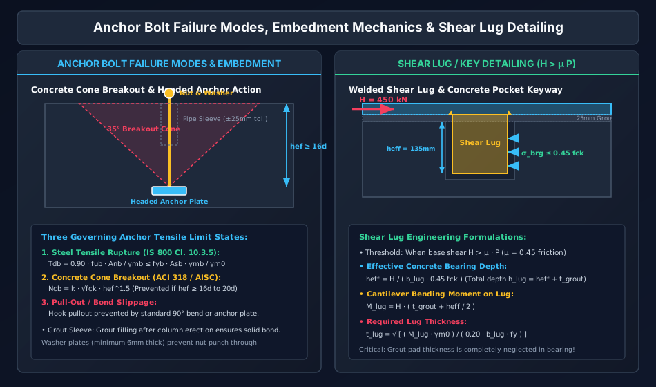
- Steel Tensile Rupture: Bolt shank yields or threads fracture in tension: where is the ultimate tensile strength of bolt material, is the net tensile thread area (), and .
- Concrete Breakout Cone: Tensile stresses in concrete exceed tensile capacity, forming a failure cone radiating from the anchor head to the top surface. Nominal cone breakout capacity per CCD method: where is the effective embedment depth.
- Pullout / Bond Slippage: Mechanical slip of hooked bars or chemical adhesive failure in post-installed anchors.
- For hooked bolts: Anchor hook length .
- For straight deformed bolts: Bond length .
- Code Rule of Thumb: to for anchor bolts with standard hooks or embedded anchor plates.
- Concrete Side-Face Blowout: Occurs when high compression under deep anchor heads bursts thin pedestal cover.
- Concrete Splitting: Tensile cracking between closely spaced bolts ().
- Bolt Shear & Prying: Shear rupture of bolt shank across the grout layer accompanied by flexure.
3.4 Horizontal Shear Transfer Mechanisms
| Mechanism | Structural Characteristics | Design Equation / Code Criterion | Application Range |
|---|---|---|---|
| Interfacial Friction | Shear transfer via friction between base plate, grout pad, and concrete footing | ( for steel on grout) |
Permissible only when is reliably compressive and |
| Anchor Bolt Dowel Action | Bolts act in combined shear and cantilever bending across the 25 mm grout pad | ( reduction for grout pad) |
Light to moderate shear (); requires welded plate washers |
| Welded Shear Lug (Key) | Heavy plate or structural tee shop-welded beneath base plate, recessed into keyway pocket | Cantilever bending of lug checked at weld line |
Heavy shear (, cranes, seismic bracing, wind base shear) |
4. Detailed Technical Diagrams & Visual Models
4.1 Moment-Resisting Base Plate Stress Block and Anchor Bolt Mechanics
The following hand-coded engineering diagram displays the triangular limit-state bearing pressure distribution, the depth of compression zone , the line of action of compressive force , the tension force developed in the holding-down bolts, and the free-body equilibrium under large overturning eccentricity ().
4.2 Anchor Bolt Embedment Failure Modes & Welded Shear Lug Detailing
The following diagram details the concrete breakout cone (), mechanical anchor plates, sleeve grouting tolerances, and the structural detailing and load path of a heavy-duty welded shear lug embedded in an engineered pedestal keyway pocket.
5. Comprehensive Step-by-Step Mathematical Derivations & Code Clauses
5.1 Derivation of Compression Depth & Bolt Tension
Given:
- Base plate dimensions: Length , Width .
- Loading: Factored axial compression , Factored overturning moment .
- Eccentricity: .
- Effective depth to tension bolts: from compressive edge.
- Concrete limit state bearing capacity: .
Assuming limit bearing pressure over triangular contact zone :
The resultant acts at distance from the extreme compressive edge. The lever arm from to the tension bolt line is:
The column axial load acts at distance from the compressive edge. Therefore, the lever arm from to the tension bolt line is:
Taking rotational equilibrium about the anchor bolt centerline:
Multiply both sides by :
Rearranging into canonical quadratic form :
Roots of the quadratic equation:
Physical admissibility condition: . The smaller root corresponds to the physical contact length.
Once is evaluated:
- Compressive force:
- Anchor bolt total tensile force:
- Required net tensile area of anchor bolts on tension side:
5.2 Combined Tension & Shear Interaction (IS 800:2007 Cl. 10.3.6)
When anchor bolts resist concurrent factored tension and factored shear :
Where:
- = Factored shear load per bolt.
- = Design shear capacity per bolt: where is the grout pad reduction factor (accounting for bending across 25 mm non-shrink grout pad).
- = Factored tensile load per bolt.
- = Design tensile capacity per bolt:
5.3 Welded Shear Lug Design Formulation
For heavy lateral shear resisting via a rectangular solid steel bar welded beneath the base plate:
- Width of lug = (parallel to base plate width).
- Total depth of lug = .
- Non-shrink grout thickness = (bearing neglected in grout layer).
- Effective bearing depth in concrete = .
-
Bearing Resistance Check against Concrete:
Total lug depth provided: .
-
Cantilever Bending Moment on Shear Lug: The concrete bearing pressure resultant acts at mid-depth of the effective embedment: below the bottom of the grout pad. Lever arm to the weld junction at the bottom of the base plate:
Cantilever bending moment:
-
Required Lug Thickness (): Treating the lug as a solid rectangular section ():
6. Three Fully Worked Unit-Checked Numerical Examples
Example 1: Moment-Resisting Base Plate with Large Uplift Eccentricity
Problem Statement:
An ISHB 400 column carries a factored axial compressive load and a factored overturning bending moment . The column is supported on a base plate of length (along the bending axis) and width resting on an M25 concrete foundation (). Two anchor bolts are provided on each side, located inward from the plate edges ( from compressive edge).
Using limit state principles:
- Verify if large eccentricity uplift occurs.
- Calculate the depth of the concrete compression zone .
- Determine total anchor bolt tension and tension per bolt.
- Design the anchor bolts using Grade 4.6 steel ().
Step-by-Step Solution:
Step 1: Check Eccentricity Regime
Kern limit of the base plate:
Since , large eccentricity uplift governs. Tensile separation occurs over the windward zone, and holding-down bolts carry net tension.
Step 2: Concrete Bearing Limit State & Quadratic Equilibrium Concrete maximum permissible bearing pressure:
Lever arm of axial load from compression edge:
The resultant axial load acts right at the extreme leeward edge. Lever arm of about the tension bolt line ():
Moment of about the tension bolt line:
Quadratic formulation for contact length :
Solving the quadratic equation:
Step 3: Compressive Force & Anchor Bolt Tension
From vertical equilibrium:
Tension per bolt ( bolts on windward side):
Step 4: Design of Anchor Bolts For Grade 4.6 bolts ():
Provide M20 Grade 4.6 bolts:
- Shank diameter
- Nominal area
- Net tensile thread area
- Capacity:
Example 2: Heavy Lateral Shear Lug Design
Problem Statement:
A steel column base plate () supports a factored column vertical load and a heavy horizontal shear force from a braced crane runway. The base plate rests on a thick non-shrink grout pad over an M25 concrete pedestal ().
- Determine if friction alone can resist the shear force (coefficient of friction ).
- Design a welded rectangular solid steel shear lug of width to transfer the full horizontal shear into the pedestal keyway.
- Calculate the total depth, cantilever bending moment, and required plate thickness of the shear lug.
Step-by-Step Solution:
Step 1: Check Interfacial Frictional Capacity
Since , friction is inadequate. A dedicated welded shear lug is mandatory. Following conservative industrial practice, design the lug for the full shear .
Step 2: Effective Embedment Depth in Concrete Concrete permissible bearing pressure:
Width of lug . Bearing resistance per unit embedment depth:
Required effective bearing depth below the grout pad:
Provide effective embedment in concrete . Accounting for the grout pad (where bearing is neglected):
Step 3: Cantilever Bending Moment at Base Plate Junction The concrete bearing pressure resultant acts at the centroid of the bearing area:
Total lever arm from the weld connection (bottom of base plate) to bearing centroid:
Cantilever bending moment:
Step 4: Lug Thickness Design For a solid rectangular plate subjected to bending:
Provide a thick solid steel plate of dimensions (width) (depth) (thickness). Full-penetration butt weld connects the shear lug to the underside of the base plate.
Example 3: Anchor Bolt Combined Tension & Shear Interaction Check
Problem Statement:
A base plate is secured with 4 Nos. M24 Grade 8.8 anchor bolts (). Under seismic load combination, each bolt is subjected to a factored tensile load and a factored shear force . A non-shrink grout pad exists between the plate and concrete.
- Compute the design tensile capacity and design shear capacity per bolt.
- Verify the combined tension-shear interaction criterion of IS 800:2007 Cl. 10.3.6.
- Determine the required standard embedment depth for the anchor bolts.
Step-by-Step Solution:
Step 1: Bolt Properties and Capacities For M24 Grade 8.8 bolts:
- Shank diameter
- Gross area
- Net tensile thread area
- Partial safety factor
Design tensile capacity:
Design shear capacity (accounting for grout pad reduction factor):
Step 2: Interaction Ratio Verification (IS 800 Cl. 10.3.6) Tensile demand ratio:
Shear demand ratio:
Combined interaction check:
The interaction index is , confirming the bolts are SAFE with substantial structural reserve.
Step 3: Embedment Depth Requirement Standard code anchorage requirement for heavy anchor bolts with welded end anchor plate:
Provide standard embedment depth with an anchor plate washer () and double lock nuts to ensure ductile steel failure precedes concrete breakout.
7. Common Engineering Pitfalls & Examination Traps
| Pitfall / Exam Trap | Erroneous Concept | Correct Physical & Code Principle |
|---|---|---|
| Trap 1: Assuming Anchor Bolts Carry Tension When | Calculating bolt tension whenever moment exists | When , the entire base plate is in compression (). Anchor bolts carry zero tension from column action; they only serve during erection. |
| Trap 2: Neglecting the Grout Layer in Shear Lug Sizing | Including the top 25 mm grout layer in concrete bearing resistance | Non-shrink cementitious grout undergoes spalling under intense localized horizontal thrust. Bearing resistance must be evaluated exclusively over concrete embedment (). |
| Trap 3: Oversized Bolt Holes & Shear Dowel Failure | Assuming standard base plate holes transfer shear without slip | Anchor bolt holes in base plates are typically punched oversized () to accommodate field erection tolerances. Dowel action cannot mobilize until substantial base slip occurs unless heavy plate washers are welded to the base plate after plumbing. |
| Trap 4: Using instead of for Bolt Tensile Fracture | Using for bolt threads | Per IS 800:2007 Cl. 10.3.5, net thread tension capacity is governed by ultimate strength: . |
| Trap 5: Ignoring Linear Bending in Shear Lugs | Treating the shear lug merely in pure shear () | The shear resultant acts at mid-depth of embedment, creating a severe cantilever overturning moment at the weld toe. Lug plate thickness is almost always governed by flexure, not pure shear! |
8. Real-World Failure Case Studies & Forensic Analysis
Forensic Investigation: Braced Industrial Mill Building Erection Collapse
- Context: A high industrial warehouse frame collapsed during a high-wind thunderstorm prior to installation of the shear lug keyways and final grout.
- Root Failure Cause:
- The design specified welded shear lugs under each column base plate to resist of base shear.
- The erection contractor erected the columns on leveling nuts on anchor bolts and omitted temporary wind guys before pouring the non-shrink grout.
- When wind gusted to , lateral shear forced the anchor bolts to act as unbraced cantilevers across a gap.
- The cyclic flexural stress across the unbraced bolts caused low-cycle fatigue brittle fracture at the first exposed thread root, triggering progressive collapse of 4 portal bays.
- Remediation & Forensic Standard: Anchor bolts must never carry horizontal shear across an un-grouted gap unless engineered specifically as cantilever stand-off pins. Erection protocols must prohibit loading until the grout has achieved compressive strength.
9. Competitive Examination Practice Problems
Problem 1 (GATE CE - 2 Marks)
A steel column base plate () is subjected to a factored axial force and factored moment . The eccentricity of the load is:
- (A) , with no uplift
- (B) , with tensile separation and bolt tension
- (C) , with full contact
- (D) , with uniform bearing pressure
Correct Answer: (B)
Step-by-Step Explanation:
The kern limit of the plate is:
Since , the load lies outside the middle third. Tensile separation occurs over the windward side, requiring anchor bolts to resist uplift tension.
Problem 2 (UPSC ESE Paper-I - 2 Marks)
Per IS 800:2007, the design tensile capacity of an anchor bolt of grade 4.6 () with net tensile area is given by:
- (A)
- (B)
- (C)
- (D)
Correct Answer: (B)
Step-by-Step Explanation:
Per IS 800:2007 Clause 10.3.5, the design tensile strength of a bolt is governed by thread rupture:
Problem 3 (SSC JE - 1 Mark)
To resist very high horizontal shear forces at a column base that exceed the frictional capacity, the most effective structural component is:
- (A) Increasing the grout thickness to 75 mm
- (B) Providing a welded shear key (lug) projecting into the concrete footing
- (C) Decreasing the base plate thickness
- (D) Using unhooked smooth anchor bolts
Correct Answer: (B)
Step-by-Step Explanation:
A welded shear key (shear lug) projecting into an engineered pocket in the concrete pedestal provides direct bearing against hardened concrete, safely transferring massive shear forces without bending the anchor bolts.
Problem 4 (State PSC AE - 2 Marks)
In designing anchor bolts for moment-resisting base plates, the minimum embedment depth into concrete for hooked bolts is typically recommended as:
- (A)
- (B)
- (C)
- (D)
Correct Answer: (C)
Step-by-Step Explanation:
To prevent premature concrete breakout cone and pullout failure before developing the full ductile yield strength of the steel anchor bolt, standard practice (IS 800/IS 456/AISC) mandates an embedment depth to .
Problem 5 (RRB JE - 1 Mark)
For an anchor bolt subjected to combined shear force and tensile force , where design capacities are and , the IS 800:2007 interaction formula is:
- (A)
- (B)
- (C)
- (D)
Correct Answer: (B)
Step-by-Step Explanation:
IS 800:2007 Clause 10.3.6 mandates the elliptical quadratic interaction equation:
10. Cross-Subject Synthesis & Advanced Structural Connections
                             CROSS-DISCIPLINARY COUPLING

    Design of Steel Structures (IS 800:2007)
    - Anchor Bolt Tension (T_db = 0.9 fub Anb / 1.25)
    - Shear Lug Cantilever Bending (M_lug = H * z)
                         |
                         v
    Reinforced Concrete Design (IS 456:2000 & ACI 318)
    - Limit Concrete Bearing Pressure (0.45 fck)
    - Concrete Breakout Cone Rupture (35° Failure Plane)
    - Anchor Plate Washer Development & Pedestal Splitting Reinforcement
                         |
                         v
    Structural Dynamics & Earthquake Engineering (IS 1893:2016)
    - Seismic Shear Reversal (Lug Bidirectional Bearing)
    - Low-Cycle Fatigue of Anchor Threads
    - Ductility Hierarchy (Steel Yielding precedes Concrete Breakout)
11. Standard Reference Textbooks & Official Code Specifications
- IS 800:2007: General Construction in Steel — Code of Practice, Bureau of Indian Standards, New Delhi. Cl. 7.4 (Column Bases), Cl. 10.3 (Bolted Connections), Cl. 10.4 (Anchor Bolts).
- IS 456:2000: Plain and Reinforced Concrete — Code of Practice, Cl. 34.4 (Permissible Bearing Stress).
- AISC Steel Design Guide 1 (2nd Edition): Base Plate and Anchor Rod Design, James M. Fisher and Lawrence A. Kloiber, American Institute of Steel Construction.
- ACI 318-19: Building Code Requirements for Structural Concrete, Chapter 17 (Anchoring to Concrete), American Concrete Institute.
- N. Subramanian: Design of Steel Structures, Oxford University Press, Chapter 13: Column Bases and Foundations.
- S.K. Duggal: Limit State Design of Steel Structures, McGraw Hill India, Chapter 10: Column Bases.
12. Comprehensive Summary, Formula Cheatsheet & Key Takeaways
===================================================================================================
                       ANCHOR BOLTS & SHEAR KEYS FORMULA CHEATSHEET
===================================================================================================
1. Eccentricity Regime:
   - e = M / P
   - If e <= L / 6  ==> Full contact, No uplift, T = 0
   - If e > L / 6   ==> Uplift occurs, Anchor bolts mobilized in direct tension

2. Moment Equilibrium about Tension Bolt Line (Contact length x_u):
   - x_u^2 - 3 d' x_u + [6 P (d' - L/2 + e)] / (0.45 f_ck B) = 0
   - Compressive Force: C = 0.5 * (0.45 f_ck) * B * x_u
   - Total Tension:     T = C - P
   - Tension per Bolt:  T_b = T / n_b

3. Bolt Tensile Capacity (IS 800 Cl. 10.3.5):
   - T_db = (0.90 * f_ub * A_nb) / gamma_mb   (gamma_mb = 1.25)

4. Combined Shear-Tension Interaction (IS 800 Cl. 10.3.6):
   - (V_sb / V_dsb)^2 + (V_tb / T_db)^2 <= 1.0
   - V_dsb = [f_ub * A_nb / (sqrt(3) * gamma_mb)] * beta_g   (beta_g = 0.80 for grout pad)

5. Shear Lug Design:
   - Effective bearing depth: h_ef = H / (0.45 f_ck * b_lug)
   - Total depth:            h_lug = h_ef + t_grout   (t_grout = 25 mm)
   - Lever arm:              z_lug = t_grout + h_ef / 2
   - Bending moment:         M_lug = H * z_lug
   - Required thickness:     t_lug = sqrt[(M_lug * gamma_m0) / (0.20 * b_lug * f_y)]

6. Anchorage Embedment Depth:
   - L_e >= 16 d to 20 d (Ensures steel yield precedes brittle concrete breakout cone)
===================================================================================================