Secondary Effects in Plastic Design (Axial Force, Shear Interaction, Cross-Section Slenderness & Lateral Restraints)
In this chapter (4 topics)
On this page
- 1. Topic Metadata
- 2. Executive Summary & Core Engineering Significance
- 3. Plastic Moment - Axial Force Interaction (P-M Interaction Mechanics)
- 3.1 Solid Rectangular Cross-Section (b × d)
- 3.2 Standard Wide-Flange I-Sections
- 4. Plastic Moment - High Shear Interaction (V-M Interaction Mechanics)
- 4.1 The von Mises Yield Criterion in the Web
- 4.2 IS 800:2007 Clause 9.2.2 High Shear Provisions
- 5. Cross-Section Classification & Local Buckling Requirements (Table 2)
- 5.1 The Four Cross-Section Classes (IS 800 Cl. 3.7)
- 5.2 Limiting Width-to-Thickness Ratios (IS 800:2007 Table 2)
- 6. Lateral-Torsional Buckling of Plastic Hinges & Lateral Restraint Detailing
- 6.1 Instability Mechanics at a Plastic Hinge
- 6.2 Minimum Spacing of Lateral Restraints (IS 800:2007 Cl. 8.2.2)
- 7. Minimum Weight Design & Serviceability Deflection Checks
- 8. Visual Architecture & Structural Diagrams
- 8.1 P-M & V-M Plastic Interaction Mechanics
- 8.2 Class 1 Plastic Slenderness Limits & Lateral Restraints
- 9. Solved Practical Design Examples
- Problem 1: Rectangular Section P-M Interaction & Capacity Reduction
- Problem 2: ISMB 400 High Shear & Moment Interaction (IS 800:2007 Cl. 9.2.2)
- Problem 3: Section Classification & Lateral Restraint Detailing for Plastic Hinge
- 10. Critical Examination Traps, Pitfalls & Countermeasures
- 11. Multi-Exam Practical Assessment Questions
- Question 1 (GATE CE - Secondary Interaction Formulations)
- Question 2 (UPSC ESE Paper 1 - Code Limits)
- Question 3 (SSC JE - Section Classification)
- Question 4 (State AE - Slenderness Criteria)
- Question 5 (RRB JE - Lateral Restraint Detailing)
- 12. Comprehensive Standard Specifications & Academic References
1. Topic Metadata
- Subject: Design of Steel Structures (IS 800:2007)
- Module: Chapter 06: Plastic Analysis and Design
- Topic ID:
STEEL-06-04 - Syllabus Coverage: GATE CE (Structural Engineering), UPSC ESE (Paper 1), SSC JE (Civil), State AE/JE, RRB JE
- Governing Standard: IS 800:2007 (Section 8: Design of Members Subjected to Combined Forces & Plastic Analysis; Section 9: Working Stress / Plastic Design of Beams; Table 2: Limiting Width-to-Thickness Ratios), AISC 360-16, EN 1993-1-1 (Eurocode 3)
- Prerequisites:
STEEL-06-01(Plastic Hinge & Shape Factors),STEEL-06-02(Virtual Work & Collapse Load Theorems),STEEL-06-03(Continuous Beams & Portal Frames)
2. Executive Summary & Core Engineering Significance
Simple plastic theory (as presented in Topics 01, 02, and 03) rests upon several foundational idealizations: pure flexure is assumed without significant axial force, shear stresses are presumed negligible, local plate buckling is suppressed, and out-of-plane lateral-torsional instability is completely prevented.
In actual structural practice—particularly in tall multi-story building frames, heavy industrial mill structures, and long-span transfer girders—these idealized assumptions are challenged by severe secondary effects:
- Plastic Interaction: High compressive or tensile axial forces consume cross-sectional yield capacity, shifting the plastic neutral axis (PNA) and creating a central axial core that drastically curtails the remaining plastic moment capacity ().
- High Shear Interaction: Under large shear forces (), the web undergoes intense shear stresses (). According to the von Mises yield criterion (), high web shear diminishes normal flexural yield resistance to near zero, forcing the flanges alone to carry the plastic bending moment.
- Class 1 (Plastic) Cross-Section Requirements: For a plastic mechanism to develop, plastic hinges must undergo substantial plastic rotation without shedding load. If local buckling intervenes prematurely in the flanges or web, the plastic plateau collapses. Hence, only Class 1 (Plastic) sections meeting strict width-to-thickness limits (IS 800 Table 2) are permitted in plastic design.
- Plastic Hinge Lateral-Torsional Restraints: As outer fibers yield fully into the strain-hardening range, the tangent modulus drops drastically (). The member loses torsional-flexural rigidity, making it acutely vulnerable to lateral-torsional buckling (LTB). Positive, closely spaced lateral restraints are legally mandated at and adjacent to plastic hinges.
3. Plastic Moment - Axial Force Interaction ( Interaction Mechanics)
When a structural steel member carries concurrent factored axial force and bending moment , the cross-section must simultaneously satisfy axial force equilibrium and moment equilibrium at the fully plastic limit state.
3.1 Solid Rectangular Cross-Section ()
Consider a solid rectangular section of width and depth , with yield strength :
- Squash load capacity:
- Pure plastic moment capacity (at ):
Derivation of the Parabolic Yield Surface:
- Under axial compression , the cross-section develops an internal stress field of magnitude (compression) and (tension).
- The axial force is resisted by a central plastic zone of depth centered symmetrically about the geometric neutral axis:
- Expressing the central core depth in terms of the axial load ratio :
- The remaining cross-section (the outer zones between and ) resists the bending moment : where the lever arm from the neutral axis to the centroid of each outer block is:
- Factoring out :
========================================================================================
RECTANGULAR SECTION P-M INTERACTION GALLERY (fy = 250 N/mm²)
----------------------------------------------------------------------------------------
Axial Ratio n = P/Py       Core Depth (2 y0 / d)     Mpr / Mp           Reduction in Mp
----------------------------------------------------------------------------------------
n = 0.00                   0.00                      1.0000             0.0% (Pure Bending)
n = 0.20                   0.20                      0.9600             4.0%
n = 0.40                   0.40                      0.8400             16.0%
n = 0.50                   0.50                      0.7500             25.0%
n = 0.60                   0.60                      0.6400             36.0%
n = 0.80                   0.80                      0.3600             64.0%
n = 1.00                   1.00                      0.0000             100.0% (Pure Squash)
========================================================================================
3.2 Standard Wide-Flange I-Sections
In standard I-sections (such as ISMB or ISMC profiles), the cross-section geometry concentrates steel area in the heavy outer flanges:
- Total area .
- Axial capacity of web: .
- Case 1: Low Axial Force (): The axial force is entirely absorbed by a central web core of depth . The heavy outer flanges remain completely uncompromised to carry bending moment: Because the web contributes very little to the major-axis plastic section modulus (), small axial forces () cause negligible reduction in .
- Case 2: High Axial Force (): The central axial plastic core penetrates into the flanges, causing a rapid decline in .
IS 800:2007 Cl. 9.3.1.2 Standard Linearized Interaction:
To simplify design while ensuring conservative bounds, IS 800:2007 provides a bilinear interaction for standard rolled I-sections bent about the major axis ():
where . For , no reduction in plastic moment capacity is required ().
4. Plastic Moment - High Shear Interaction ( Interaction Mechanics)
4.1 The von Mises Yield Criterion in the Web
Under pure shear, structural steel yields at the shear yield stress:
The design plastic shear resistance of a section is:
where for rolled I-sections.
When shear force and bending moment act simultaneously on a beam cross-section:
- If average shear stress is small, the normal stress capacity , so the plastic moment is unaffected.
- If shear stress is large, in the web is severely depressed. At , , meaning the web can carry zero bending moment!
4.2 IS 800:2007 Clause 9.2.2 High Shear Provisions
IS 800 establishes a clean threshold for high shear:
- Low Shear Case (): Shear deformation does not degrade the plastic bending capacity.
- High Shear Case (): The design plastic moment resistance is curtailed to: where: and is the plastic design moment resistance of the flanges alone:
Physical Interpretation of the Factor:
- At : .
- At : . The web is fully consumed by shear yielding, and the beam's flexural capacity reduces completely to that of the two flanges!
5. Cross-Section Classification & Local Buckling Requirements (Table 2)
Plastic analysis assumes that after reaching , a cross-section can undergo indefinite plastic rotation without loss of moment capacity. However, thin plate elements subjected to compression will buckle locally.
M ↑
  │          Class 1 (Plastic): Long rotation plateau (R ≥ 4.0)
Mp├───────────┈┈┈┈┈┈┈┈┈┈┈┈┈┈┈┈┈┈┈┈┈┈┈┈┈┈┈┈┈┈
  │          / \  Class 2 (Compact): Reaches Mp, buckles shortly after
My├───-     /   \
  │  / \   /     \  Class 3 (Semi-Compact): Reaches My, buckles before Mp
  │ /   \ /       \
  │/     X         \  Class 4 (Slender): Buckles elastically before My
──┴──────────────────────→ θ (Rotation)
5.1 The Four Cross-Section Classes (IS 800 Cl. 3.7)
- Class 1 (Plastic): Cross-sections that can develop their full plastic moment capacity and sustain a plastic rotation plateau of without local buckling. Mandatory for plastic analysis and design.
- Class 2 (Compact): Cross-sections that can develop full plastic moment , but have limited rotation capacity due to local buckling. Permitted only in elastic analysis with plastic section modulus ().
- Class 3 (Semi-Compact): Cross-sections where the extreme outer fiber can reach yield stress (), but local buckling prevents development of . Designed elastically using .
- Class 4 (Slender): Cross-sections where local buckling occurs in the elastic range before the outer fiber reaches . Must be designed with reduced effective width ().
5.2 Limiting Width-to-Thickness Ratios (IS 800:2007 Table 2)
The yield stress ratio parameter is defined as:
====================================================================================================
IS 800:2007 TABLE 2 LIMITING WIDTH-TO-THICKNESS RATIOS
----------------------------------------------------------------------------------------------------
Element Type                              Class 1 (Plastic)      Class 2 (Compact)     Class 3 (Semi-Compact)
====================================================================================================
Flange Outstand (Rolled I-section)        b / tf ≤ 9.4 ε         b / tf ≤ 10.5 ε       b / tf ≤ 15.7 ε
Flange Outstand (Welded Plate Girder)     b / tf ≤ 8.4 ε         b / tf ≤ 9.4 ε        b / tf ≤ 13.6 ε
Web in Pure Bending (NA at mid-depth)     d / tw ≤ 84 ε          d / tw ≤ 105 ε        d / tw ≤ 126 ε
Web with Combined Axial & Bending         d / tw ≤ 84 ε/(1+r)    d / tw ≤ 105 ε/(1+r)  d / tw ≤ 126 ε/(1+r)
Circular Hollow Section (CHS)             D / t ≤ 42 ε²          D / t ≤ 52 ε²         D / t ≤ 146 ε²
Rectangular Hollow Section (RHS) Flange   b / t ≤ 29.3 ε         b / t ≤ 33.5 ε        b / t ≤ 42.0 ε
====================================================================================================
[!IMPORTANT] Strict Prohibition: Under IS 800:2007 Section 8 and Section 12, plastic hinge formation is legally prohibited in any structural member that does not satisfy Class 1 (Plastic) slenderness criteria. If a section is Class 2, 3, or 4, elastic global analysis must be performed.
6. Lateral-Torsional Buckling of Plastic Hinges & Lateral Restraint Detailing
6.1 Instability Mechanics at a Plastic Hinge
When an I-beam bends about its major axis, the compression flange behaves like an axially compressed strut. In the elastic range, flexural rigidity and warping rigidity stabilize the beam against twisting. However, when a plastic hinge forms:
- Both the compression and tension flanges are fully yielded ().
- The tangent modulus of elasticity drops from to the strain-hardening modulus or .
- Effective torsional and lateral stiffness vanish locally, triggering catastrophic out-of-plane lateral-torsional buckling (LTB) unless positive physical bracing is provided.
6.2 Minimum Spacing of Lateral Restraints (IS 800:2007 Cl. 8.2.2)
To ensure the plastic mechanism can form without premature out-of-plane buckling, IS 800 mandates:
- Mandatory Restraint at Hinge Locations: A positive lateral restraint must be positioned within a distance of from the cross-section where a plastic hinge is designed to form.
- Maximum Permissible Lateral Restraint Spacing ():
The distance between adjacent lateral restraints on the compression flange shall not exceed:
where:
- is the radius of gyration of the member about its minor axis.
- is the ratio of clear web depth to flange thickness.
- Simplified Rules of Thumb for Preliminary Detailing:
- Bracing Force Requirement (IS 800 Cl. 8.2.2.3): Each lateral bracing assembly (cross-beam, diagonal truss, or sag-rod tie) must be designed to withstand a lateral force equal to at least of the maximum factored compressive force in the flange:
7. Minimum Weight Design & Serviceability Deflection Checks
While plastic design ensures safety against ultimate collapse, real-world steel design must verify serviceability limit states (SLS):
- Deflection Check at Service Loads: Because plastic sections are leaner than their elastic counterparts, deflections under service loads (, where is the load factor) are larger. The service deflection must satisfy:
- Deflection Calculation via Virtual Work: The deflection at service load prior to plastic hinge formation can be evaluated using elastic virtual work or moment-area theorems on the unyielded frame.
- Alternating Plasticity & Incremental Collapse: In structures subjected to cyclic or reversing live loads (e.g., bridge girders, crane runways), repeated plastification can lead to low-cycle fatigue or progressive plastic deformation (shakedown failure).
8. Visual Architecture & Structural Diagrams
8.1 P-M & V-M Plastic Interaction Mechanics
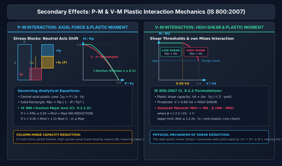
The diagram below details the cross-sectional stress blocks, central axial core formation, normalized yield surfaces, and the IS 800:2007 Clause 9.2.2 high-shear reduction factor :
8.2 Class 1 Plastic Slenderness Limits & Lateral Restraints
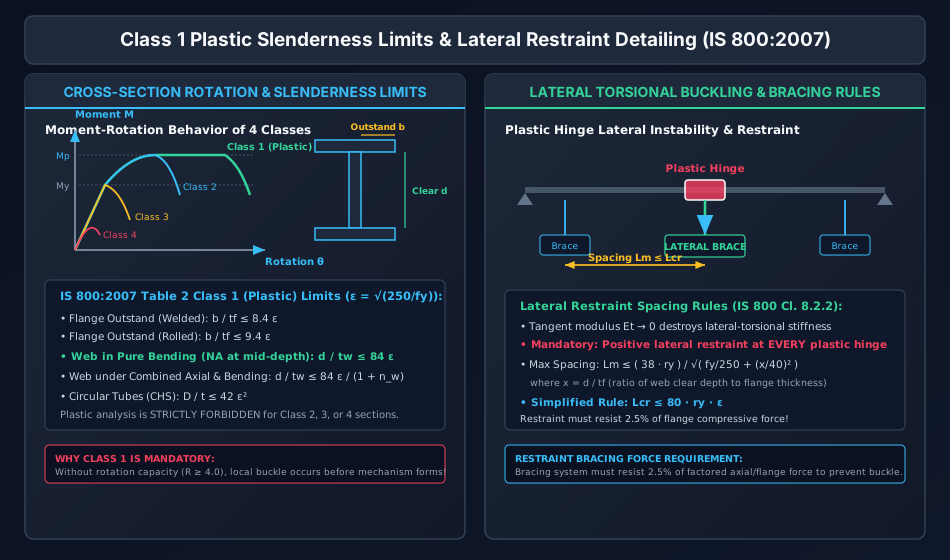
The diagram below illustrates the four moment-rotation behavioral classes, limiting width-to-thickness ratios per Table 2, plastic hinge stiffness degradation, and lateral restraint detailing rules:
9. Solved Practical Design Examples
Problem 1: Rectangular Section P-M Interaction & Capacity Reduction
Problem Statement: A solid rectangular steel beam-column has cross-sectional dimensions and , fabricated from Fe 410 steel with yield strength .
- Compute the axial squash load , plastic section modulus , and full plastic moment capacity .
- If the column is subjected to a factored axial compression force , determine the axial load ratio , the depth of the central axial plastic core , and the reduced plastic moment capacity .
- Evaluate the percentage reduction in plastic moment capacity.
- Construct a table of for axial load ratios .
Step-by-Step Mathematical Solution:
Step 1: Section Properties & Unreduced Capacities
- Cross-sectional area:
- Axial squash load:
- Elastic section modulus:
- Plastic section modulus:
- Full plastic moment capacity ():
Step 2: Effect of Axial Load
- Axial load ratio:
- Half-depth of central axial plastic core: Total central core depth (out of total depth).
- Reduced plastic moment capacity:
- Percentage reduction:
Step 3: P-M Interaction Spectrum Using :
- For ()
- For ()
- For ()
- For ()
- For ()
- For ()
- For ()
Problem 2: ISMB 400 High Shear & Moment Interaction (IS 800:2007 Cl. 9.2.2)
Problem Statement: A simply supported beam fabricated from ISMB 400 rolled steel section () carries heavy industrial machinery. At a critical cross-section near the support, the factored design forces are:
- Factored bending moment
- Factored shear force Section properties of ISMB 400:
- Overall depth , flange width
- Flange thickness , web thickness
- ,
- Determine the design plastic shear capacity and ascertain if a high shear condition exists.
- Calculate the design plastic moment capacity of the flanges alone ().
- Evaluate the shear interaction factor and the reduced design plastic moment resistance .
- Verify the section against the upper limit and check structural adequacy.
Step-by-Step Mathematical Solution:
Step 1: Shear Capacity & Threshold Check
- Shear area for rolled section:
- Design plastic shear resistance:
- Low shear threshold:
- Comparison:
Step 2: Flexural Capacities ( and )
- Full plastic design moment capacity ():
- Plastic design resistance of flanges alone (): Distance between flange centroids .
Step 3: Shear Interaction Factor and Reduced Moment
- Ratio of applied shear to shear capacity:
- Interaction factor :
- Reduced design plastic moment resistance per IS 800 Cl. 9.2.2:
Step 4: Upper Limit & Section Adequacy Check
- Upper limit check per Cl. 9.2.2 to prevent excessive elastic-plastic deformation: Since , the reduced capacity is governed by .
- Verification against applied factored moment:
Problem 3: Section Classification & Lateral Restraint Detailing for Plastic Hinge
Problem Statement: A welded built-up I-section rafter is designed for an industrial portal frame where plastic hinges are scheduled to form at eaves joint and apex ridge . Steel grade is Fe 410 (). The cross-sectional dimensions are:
- Flanges:
- Web: Clear depth , thickness
- Minor axis radius of gyration
- Check whether the cross-section qualifies as Class 1 (Plastic) per IS 800:2007 Table 2.
- If the flange outstand exceeds Class 1 limits, determine the maximum permissible flange width to achieve Class 1 status.
- Calculate the maximum permissible spacing of lateral restraints and to suppress lateral-torsional buckling adjacent to the plastic hinge.
- Calculate the required design bracing force for the compression flange restraint.
Step-by-Step Mathematical Solution:
Step 1: Section Classification (Table 2)
- Material parameter:
- Flange outstand for welded section:
- Flange slenderness ratio: Table 2 limit for welded flange (Class 1 Plastic): Since , the flanges are Class 1 (Plastic).
- Web slenderness ratio in pure bending: Table 2 limit for web in pure bending (Class 1 Plastic): Since , the web is Class 1 (Plastic).
- Overall Classification: The section strictly qualifies as Class 1 (Plastic). Full plastic mechanism analysis is valid.
Step 2: Lateral Restraint Spacing Detailing
- Clause 8.2.2 Exact Formula ():
- Simplified Rule of Thumb (): The exact formula of Cl. 8.2.2 governs: adjacent lateral restraints must be spaced at .
- Mandatory Hinge Restraint: A positive lateral restraint must be installed within of the hinge at eave and ridge .
Step 3: Design Bracing Force Requirement
- Factored compressive force in the flange at plastic collapse:
- Lateral restraint design force (IS 800 Cl. 8.2.2.3):
The purlin/bracing connection to the rafter flange must be detailed to resist a minimum lateral thrust of .
10. Critical Examination Traps, Pitfalls & Countermeasures
========================================================================================================================
EXAM TRAP IDENTIFIER                   FATAL ERROR TO AVOID                               CORRECT ENGINEERING PROCEDURE
========================================================================================================================
1. P-M Reduction in Rolled I-Sections  Applying linear reduction for small axial loads    IS 800 Cl. 9.3.1.2 explicitly provides
                                       (n ≤ 0.20), unnecessarily penalizing Mp.           a plateau: if n ≤ 0.20, Mnd = Mpd!
                                                                                          Reduction occurs only when n > 0.20.
------------------------------------------------------------------------------------------------------------------------
2. High Shear Threshold Misconception  Assuming high shear reduction starts at           IS 800 Cl. 9.2.2 defines low shear up to
                                       V = 0.50 Vd or V = 0.70 Vd.                        0.60 Vd. High shear is strictly V > 0.60 Vd.
------------------------------------------------------------------------------------------------------------------------
3. Flange Alone Plastic Moment Mfd     Using the full section modulus Zp in Mfd,          Mfd is the plastic capacity of the FLANGES
                                       ignoring web removal.                              ALONE: Mfd = bf tf (h - tf) fy / γm0.
------------------------------------------------------------------------------------------------------------------------
4. Plastic Analysis on Class 2 Sections Allowing plastic collapse mechanism method        Class 2 sections can reach Mp but lack
                                       for Class 2 (Compact) cross-sections.              rotation capacity (R ≥ 4.0). Plastic
                                                                                          analysis is STRICTLY restricted to Class 1.
------------------------------------------------------------------------------------------------------------------------
5. Lateral Restraint Bracing Load      Assuming lateral braces carry zero force           Braces must resist at least 2.5% of the
                                       because the main load is vertical.                 flange squash force: F_brace ≥ 0.025 P_flange.
========================================================================================================================
11. Multi-Exam Practical Assessment Questions
Question 1 (GATE CE - Secondary Interaction Formulations)
For a solid rectangular beam of width and depth subjected to an axial compressive force equal to half its squash load (), the reduced plastic moment capacity in terms of the pure plastic moment is:
- (A)
- (B)
- (C)
- (D)
Answer: (B) Detailed Solution: For a solid rectangular section, the reduced plastic moment is given by . With :
Question 2 (UPSC ESE Paper 1 - Code Limits)
According to IS 800:2007, under combined bending and shear in a beam, the reduction in design plastic moment capacity is required only when the design shear force exceeds:
- (A)
- (B)
- (C)
- (D)
Answer: (C) Detailed Solution: Per IS 800:2007 Clause 9.2.2, when , the design bending resistance is (unaffected by shear). When , high shear interaction reduces the design bending resistance to .
Question 3 (SSC JE - Section Classification)
Which of the following cross-sectional classes is PERMITTED for use in plastic analysis and design under IS 800:2007?
- (A) Class 1 (Plastic) only
- (B) Class 1 (Plastic) and Class 2 (Compact)
- (C) Class 1, Class 2, and Class 3 (Semi-Compact)
- (D) All four classes provided load factor is increased
Answer: (A) Detailed Solution: Plastic analysis strictly requires that the cross-section possesses sufficient plastic hinge rotation capacity () without undergoing premature local buckling. Only Class 1 (Plastic) sections fulfill this requirement.
Question 4 (State AE - Slenderness Criteria)
For an outstanding flange of a welded I-section made of Fe 410 steel (), the maximum width-to-thickness ratio () to qualify as a Class 1 (Plastic) section is:
- (A)
- (B)
- (C)
- (D)
Answer: (B) Detailed Solution: Per IS 800:2007 Table 2:
- Rolled section flange outstand: (Class 1).
- Welded plate girder flange outstand: (Class 1). Because residual welding stresses at the web-flange junction lower local buckling resistance, the welded limit is strictly .
Question 5 (RRB JE - Lateral Restraint Detailing)
What minimum percentage of the flange compressive force must a lateral brace resist when placed to prevent lateral-torsional buckling of a plastic hinge?
- (A)
- (B)
- (C)
- (D)
Answer: (C) Detailed Solution: Per IS 800:2007 Clause 8.2.2.3, lateral restraints stabilizing the compression flange at or near plastic hinge locations must be designed to resist an equivalent lateral force of not less than of the maximum factored compressive force in the flange.
12. Comprehensive Standard Specifications & Academic References
- Bureau of Indian Standards (BIS):
- IS 800:2007: General Construction in Steel — Code of Practice (Third Revision). Section 3 (Classification of Cross-Sections, Table 2); Section 8 (Members Subjected to Combined Forces & Plastic Analysis); Section 9 (Working Stress / Plastic Design of Beams, Cl. 9.2.2 & 9.3.1.2); Section 12 (Plastic Design).
- American Institute of Steel Construction (AISC):
- AISC 360-16: Specification for Structural Steel Buildings. Chapter B (Design Requirements & Member Properties); Chapter F (Design of Members for Flexure); Appendix 1 (Design by Inelastic Analysis).
- European Committee for Standardization (CEN):
- EN 1993-1-1:2005 (Eurocode 3): Design of Steel Structures — Part 1-1: General Rules and Rules for Buildings. Section 5.5 (Classification of Cross-Sections); Section 6.2 (Cross-Section Resistance under M-N-V Interaction).
- Foundational Academic Textbooks:
- Baker, J. F., & Heyman, J. (1969). Plastic Design of Frames: Volume 1 & 2. Cambridge University Press.
- Horne, M. R. (1979). Plastic Theory of Structures. Pergamon Press.
- Neal, B. G. (1977). The Plastic Methods of Structural Analysis. Chapman and Hall.
- Subramanian, N. (2016). Design of Steel Structures (Limit State Method). Oxford University Press.