Gusseted Base Design for Heavy Axial & Bending Loads
In this chapter (3 topics)
On this page
- 1. Topic Metadata
- 2. Executive Summary & Core Engineering Significance
- 3. Anatomical Breakdown & Load Path in Gusseted Bases
- 3.1 Primary Structural Components
- 3.2 Dual Load-Transfer Paths (IS 800 Cl. 7.4.1)
- 4. Cantilever Overhang Reduction Mechanics & Critical Section at Gusset Angle Toe
- 4.1 Comparison of Cantilever Spans: Slab Base vs. Gusseted Base
- 5. Base Plate Thickness Formulation & Combined Action with Gusset Angle
- 5.1 Cantilever Bending Moment at the Toe
- 5.2 Required Thickness Formulation (IS 800:2007 Cl. 7.4.3.2)
- 5.3 Combined Action with Gusset Angle (Composite Bending)
- 6. Fastener & Weld Design (Vertical & Horizontal Weld Groups)
- 6.1 Column-to-Gusset Plate Welds (Vertical Weld Lines)
- 6.2 Gusset Angle-to-Base Plate Welds (Horizontal Weld Lines)
- 7. Gusseted Bases Subjected to Combined Axial Load & Bending Moment
- 7.1 Eccentricity & Kern Limit Criteria
- 7.2 Critical Cantilever Moment under Trapezoidal Bearing Pressure
- 8. Visual Architecture & Structural Diagrams
- 8.1 Gusseted Base Assembly Elevation & Plan Layout
- 8.2 Critical Moment at Gusset Toe & Weld Force Flow
- 9. Solved Practical Design Examples
- Problem 1: Heavy Column Gusseted Base Design with Machined Ends
- Problem 2: Gusseted Base under Axial Load & Bending Moment (No Tension Case)
- Problem 3: Unmachined Column End Weld Sizing (100% Load Transfer)
- 10. Critical Examination Traps, Pitfalls & Countermeasures
- 11. Multi-Exam Practical Assessment Questions
- Question 1 (GATE CE - Critical Cantilever Section)
- Question 2 (UPSC ESE Paper 1 - Plate Thickness Equation)
- Question 3 (SSC JE - Purpose of Gusseted Base)
- Question 4 (State AE - Welded Load Transfer)
- Question 5 (RRB JE - Gusset Angle Configuration)
- 12. Comprehensive Standard Specifications & Academic References
1. Topic Metadata
- Subject: Design of Steel Structures (IS 800:2007)
- Module: Chapter 07: Column Bases and Foundations
- Topic ID:
STEEL-07-02 - Syllabus Coverage: GATE CE (Structural Engineering), UPSC ESE (Paper 1), SSC JE (Civil), State AE/JE, RRB JE
- Governing Standard: IS 800:2007 (Section 7: Clause 7.4.3.2: Gusseted Bases; Clause 7.4.1: General Requirements), AISC 360-16 (Steel Design Guide 1), EN 1993-1-8 (Eurocode 3: Design of Joints)
- Prerequisites:
STEEL-07-01(Slab Base Design & Concrete Bearing),STEEL-03-01(Compression Members),STEEL-01-02(Welded Connections)
2. Executive Summary & Core Engineering Significance
While slab bases (Topic STEEL-07-01) offer an economical solution for light to moderate compressive loads, they become impractical when columns carry very heavy axial forces () or concurrent overturning bending moments. Under such high loads, an unreinforced slab base requires large cantilever projections (), resulting in excessive plate bending moments and impractical plate thicknesses () that are costly to procure and difficult to weld without lamellar tearing.
A gusseted base resolves this structural challenge through component triangulation:
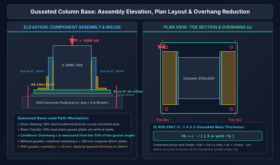
- Cantilever Overhang Reduction: By introducing vertical gusset plates () and heavy gusset angles (e.g., ISA ), the critical bending section is shifted outward from the face of the column to the toe of the gusset angle. The cantilever span is curtailed to a fraction of the slab base projection (), reducing the plate bending moment by .
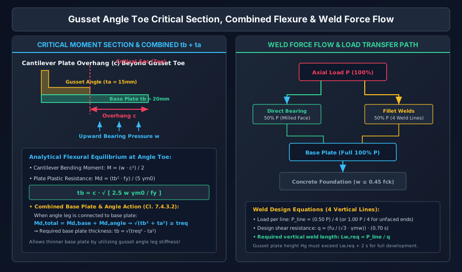
- Combined Flexural Action: Per IS 800:2007 Clause 7.4.3.2, when the horizontal leg of the gusset angle is rigidly connected to the base plate, both elements act compositely in flexure: , allowing the designer to specify a substantially thinner base plate ().
- Multi-Planar Load Distribution: Gusset plates distribute vertical load across multiple vertical weld lines, preventing stress concentration in the column flanges and enabling smooth stress dispersion into the concrete pedestal at an effective angle.
3. Anatomical Breakdown & Load Path in Gusseted Bases
                               COLUMN (ISHB / 2 ISMC)
                                       │  │
                                       │  │
             GUSSET PLATES (tg) ──────►│  │◄────── GUSSET PLATES (tg)
                                       │  │
            GUSSET ANGLES (ISA) ────►┌─┘  └─┐◄──── GUSSET ANGLES (ISA)
                         BASE PLATE ─┴──────┴─ (tb)
                     GROUT BEDDING  ══════════ (25 - 50 mm)
                  CONCRETE PEDESTAL ▓▓▓▓▓▓▓▓▓▓ (fck)
3.1 Primary Structural Components
A standard gusseted base consists of five interconnected elements:
- Steel Column Core: Heavily loaded rolled wide-flange section (e.g., ISHB 400/450) or built-up section (e.g., two channels laced/battened or placed back-to-back, or built-up box column).
- Gusset Plates: Vertical steel plates attached to the column flanges (or webs). Thickness (commonly ) with height sufficient to accommodate the required length of vertical connection welds or bolts ().
- Gusset Angles: Structural steel angles—typically unequal angles such as ISA or ISA —placed with the larger vertical leg welded/bolted to the gusset plate and the shorter horizontal leg resting upon and connected to the base plate.
- Base Plate: Solid steel plate of width and length , supporting the entire column-gusset assembly.
- Fasteners & Welds: Shop fillet welds or high-strength bolts connecting the column to gusset plates, and gusset angles to the base plate.
3.2 Dual Load-Transfer Paths (IS 800 Cl. 7.4.1)
The load transmission mechanism depends on the fabrication standard of the column ends:
- Condition 1: Machined / Faced Ends in Full Contact: The vertical welds connecting column flanges to the gusset plates are sized to carry only of the factored compressive load.
- Condition 2: Unmachined / Saw-Cut Ends: The vertical welds must be designed to transmit of the factored column axial load into the gusset plates, whence the load flows through the gusset angles into the base plate.
4. Cantilever Overhang Reduction Mechanics & Critical Section at Gusset Angle Toe
4.1 Comparison of Cantilever Spans: Slab Base vs. Gusseted Base
In a slab base, the cantilever overhang begins at the face of the column flange:
For a heavy column () on a plate, the overhang is . The cantilever moment is:
In a gusseted base, the vertical gusset plate () and the horizontal leg of the gusset angle () extend the rigid core of the column outward:
For :
The actual cantilever overhang beyond the toe of the gusset angle is:
The cantilever bending moment at the toe is:
5. Base Plate Thickness Formulation & Combined Action with Gusset Angle
5.1 Cantilever Bending Moment at the Toe
Under uniform upward bearing pressure , the critical bending moment per unit width () at the toe of the gusset angle is:
5.2 Required Thickness Formulation (IS 800:2007 Cl. 7.4.3.2)
Equating the cantilever moment to the plastic moment resistance of the plate :
5.3 Combined Action with Gusset Angle (Composite Bending)
When the horizontal leg of the gusset angle (thickness ) is securely bolted or continuously welded to the base plate along both the heel and toe, the angle leg and the base plate act together to resist the moment at the column face. The total design flexural resistance is the sum of the plastic capacities of the base plate and angle leg:
Therefore, the effective combined thickness must satisfy:
where is the required thickness calculated from the moment at the column face.
[!NOTE] Even if calculated from the toe overhang is very small, practical construction dictates a minimum base plate thickness for gusseted bases to prevent warping during welding and ensure rigid anchor bolt clamping.
6. Fastener & Weld Design (Vertical & Horizontal Weld Groups)
6.1 Column-to-Gusset Plate Welds (Vertical Weld Lines)
The factored compressive load transferred through welds is (faced ends) or (unfaced ends).
- This force is distributed across 4 vertical fillet weld lines connecting the column flanges to the two vertical gusset plates (two weld lines per flange):
- For a fillet weld of size with effective throat thickness : For Fe 410 steel ():
- Required Effective Vertical Weld Length:
- The overall height of the gusset plate must accommodate this weld length plus end returns:
6.2 Gusset Angle-to-Base Plate Welds (Horizontal Weld Lines)
The horizontal leg of each gusset angle is welded to the base plate along its toe and heel:
- Total horizontal weld lines = 2 angles 2 edges (toe + heel) = 4 horizontal weld lines.
- These welds transfer vertical shear and horizontal base shear into the base plate.
- Sized similarly to resist the full vertical load: .
7. Gusseted Bases Subjected to Combined Axial Load & Bending Moment
When a column base is subjected to concurrent axial load and overturning bending moment (e.g., from crane gantry surge, wind frames, or portal knee reactions):
        P, M
        ↓↓ ↺
   ─────┴──┴─────
   ▲            ▲
  w_max        w_min (e ≤ L/6: No Tension)
7.1 Eccentricity & Kern Limit Criteria
The effective load eccentricity is:
For a rectangular base plate of length parallel to the moment vector and width :
- Condition 1: Small Eccentricity (): The resultant falls inside the kern of the base plate. Compressive bearing stress exists over the entire footprint (). No tensile separation occurs, and anchor bolts carry zero tension:
- Condition 2: Large Eccentricity ():
The resultant falls outside the kern. The windward edge separates from the grout bed, inducing tension in the anchor bolts and creating a triangular bearing pressure block under the leeward edge. (Treated in detail in Topic
STEEL-07-03).
7.2 Critical Cantilever Moment under Trapezoidal Bearing Pressure
Under small eccentricity (), the bearing pressure over the cantilever overhang at the heavily loaded edge varies trapezoidally from at the outer edge to at the angle toe:
The bending moment at the toe is obtained by integrating the trapezoidal pressure:
This moment governs the required base plate thickness .
8. Visual Architecture & Structural Diagrams
8.1 Gusseted Base Assembly Elevation & Plan Layout
The diagram below details the complete 3D component breakdown, elevation view showing ISMC 350 column, 16 mm gusset plates, ISA angles, base plate, and plan view highlighting the critical toe section and overhang :
8.2 Critical Moment at Gusset Toe & Weld Force Flow
The diagram below illustrates the cantilever moment mechanics at the angle toe, combined action , and the 4-line vertical weld load path:
9. Solved Practical Design Examples
Problem 1: Heavy Column Gusseted Base Design with Machined Ends
Problem Statement: A built-up column consisting of 2 ISMC 350 channels placed back-to-back () carries a factored axial compressive load . The column base is supported on an M20 concrete foundation pedestal (). Steel grade is Fe 410 ().
- Column ends and base plate are machined for full contact bearing.
- Gusset plates: thick.
- Gusset angles: 2 ISA (longer leg vertical, shorter leg horizontal ). Determine:
- Permissible concrete bearing pressure and required base plate area.
- Optimum plan dimensions and , and assembly width across gusset angle toes .
- Cantilever overhang beyond the gusset angle toe.
- Required base plate thickness and compare with an unreinforced slab base.
- Sizing and vertical length of column-to-gusset fillet welds.
Step-by-Step Mathematical Solution:
Step 1: Permissible Bearing Strength & Area of Base Plate
- Design bearing strength of M20 concrete:
- Minimum required plate area:
Step 2: Proportioning Base Plate Dimensions
- Assembly width across the toes of the gusset angles:
- Select standard base plate dimensions:
- Provide length across gusset assembly:
- Provide width parallel to gussets:
- Provided Area:
- Actual uniform upward bearing pressure:
Step 3: Cantilever Overhang Beyond Gusset Angle Toe
- The cantilever overhang of the base plate beyond the toe of the gusset angle is:
Step 4: Required Base Plate Thickness () & Comparison
- Cantilever bending moment at the toe per unit width:
- Minimum required base plate thickness per IS 800 Cl. 7.4.3.2:
- Dramatic Contrast with Slab Base: If a plain slab base without gussets were used, the cantilever projection would be:
- Practical Selection: To prevent welding distortion and ensure robust anchor bolt seating, provide a standard base plate of thickness . Combined thickness with angle leg: .
Step 5: Column-to-Gusset Fillet Weld Sizing
- Column ends are machined for direct bearing:
- Distributed across 4 vertical weld lines:
- Provide shop fillet welds ():
- Required effective vertical weld length per line:
- Provide a gusset plate height (). Fully adequate!
Problem 2: Gusseted Base under Axial Load & Bending Moment (No Tension Case)
Problem Statement: A steel column gusseted base carries a factored axial compressive load and a concurrent factored bending moment . The base plate dimensions are (in the direction of the moment) and . Concrete foundation grade is M20 ().
- Determine the load eccentricity and check whether tensile separation occurs.
- Calculate the maximum and minimum concrete bearing pressures.
- If the cantilever overhang at the heavily loaded edge beyond the gusset angle toe is , compute the critical cantilever bending moment and required base plate thickness .
Step-by-Step Mathematical Solution:
Step 1: Eccentricity & Kern Limit Verification
- Load eccentricity:
- Kern limit of the rectangular base:
- Check: The entire base plate remains in positive compressive contact with the grout.
Step 2: Maximum & Minimum Bearing Pressures
- Base plate area:
- Average compressive stress:
- Extreme bearing pressures:
- Bearing check:
Step 3: Cantilever Bending Moment & Thickness ()
- Pressure at the root of the cantilever (toe of gusset angle, from outer edge):
- Bending moment of trapezoidal pressure about the toe root per unit width:
- Required base plate thickness :
- Utilizing combined action with gusset angle horizontal leg ():
- Select a standard base plate of thickness (or ).
Problem 3: Unmachined Column End Weld Sizing (100% Load Transfer)
Problem Statement: A column ISHB 400 carrying factored axial compressive load has unmachined / rough saw-cut ends. The load is transmitted to two vertical gusset plates () through 4 vertical fillet weld lines (two on each flange). Design the fillet welds using weld size and determine the required gusset plate height .
Step-by-Step Mathematical Solution:
Step 1: Load to be Transmitted by Welds
- Per IS 800:2007 Clause 7.4.1, because column ends are unfaced, zero direct bearing is allowed:
- Distributed across 4 vertical weld lines:
Step 2: Weld Capacity & Required Length
- For shop fillet weld ():
- Required effective weld length per line:
- Total required gusset plate height:
- Provide a gusset plate of height .
10. Critical Examination Traps, Pitfalls & Countermeasures
========================================================================================================================
EXAM TRAP IDENTIFIER                   FATAL ERROR TO AVOID                               CORRECT ENGINEERING PROCEDURE
========================================================================================================================
1. Cantilever Overhang Origin          Measuring cantilever projection c from the column  In a gusseted base, the critical
                                       flange instead of the gusset angle toe.            cantilever section is at the TOE of the
                                                                                          gusset angle: c = [L - (D+2tg+2lh)]/2.
------------------------------------------------------------------------------------------------------------------------
2. Faced Ends Weld Load Credit         Designing welds for 100% axial force when ends     If ends are faced/machined, welds carry
                                       are explicitly stated as machined or faced.        ONLY 50% of the axial force (Cl. 7.4.1).
------------------------------------------------------------------------------------------------------------------------
3. Unfaced Ends Bearing Credit         Assuming 50% direct bearing credit when column     If ends are unfaced or flame-cut, welds
                                       ends are saw-cut or unmachined.                    MUST be designed for 100% of the axial force.
------------------------------------------------------------------------------------------------------------------------
4. Gusset Angle Composite Flexure      Ignoring the gusset angle thickness ta in the      When angle is fastened to base plate,
                                       base plate thickness evaluation.                   use combined resistance: √(tb² + ta²) ≥ treq.
------------------------------------------------------------------------------------------------------------------------
5. Gusset Plate Minimum Thickness      Specifying thin gusset plates (tg = 8 or 10 mm)    Gusset plates in heavy column bases must
                                       under heavy axial loads.                           have tg ≥ 16 mm to prevent shear buckling.
========================================================================================================================
11. Multi-Exam Practical Assessment Questions
Question 1 (GATE CE - Critical Cantilever Section)
In a gusseted column base, the critical section for maximum cantilever bending moment in the base plate is located at:
- (A) The centerline of the column
- (B) The face of the column flange
- (C) The toe of the gusset angle
- (D) The center of the anchor bolt hole
Answer: (C) Detailed Solution: In a gusseted base, the gusset plates and gusset angles stiffen the plate. The outer cantilever overhang begins at the toe of the gusset angle. Hence, the critical section for cantilever bending moment is at the toe of the gusset angle.
Question 2 (UPSC ESE Paper 1 - Plate Thickness Equation)
Per IS 800:2007, the minimum thickness of a base plate in a gusseted base having an overhang beyond the gusset angle toe under uniform bearing pressure is:
- (A)
- (B)
- (C)
- (D) Both (A) and (C) are mathematically identical
Answer: (D) Detailed Solution: Per IS 800:2007 Clause 7.4.3.2, the bending moment at the toe is . Equating to gives . Both forms (A) and (C) are identical.
Question 3 (SSC JE - Purpose of Gusseted Base)
Gusseted bases are preferred over slab bases when:
- (A) The column carries light axial loads with large moments
- (B) The column carries heavy axial loads and slab base thickness becomes excessive
- (C) The concrete foundation has very high compressive strength
- (D) Fasteners cannot be used
Answer: (B) Detailed Solution: For heavy axial loads (), an ordinary slab base requires an excessively thick plate (). Gusseted bases reduce the cantilever span , keeping the plate thickness within economical and practical limits ().
Question 4 (State AE - Welded Load Transfer)
For a heavy column carrying factored load with machined ends in direct contact bearing, the welds connecting the column to the gusset plate must be designed for:
- (A)
- (B)
- (C)
- (D)
Answer: (C) Detailed Solution: Per IS 800:2007 Clause 7.4.1, machined ends in direct contact transfer of the compressive force by direct bearing (), and the welds are designed to transfer the remaining ().
Question 5 (RRB JE - Gusset Angle Configuration)
In a gusseted base, unequal gusset angles are typically placed with:
- (A) Shorter leg vertical against the gusset plate
- (B) Longer leg vertical against the gusset plate
- (C) Legs horizontal in opposite directions
- (D) Without gusset plates
Answer: (B) Detailed Solution: The longer vertical leg provides maximum vertical contact depth to accommodate the required length of horizontal and vertical connection welds or bolts, while the shorter horizontal leg rests upon the base plate.
12. Comprehensive Standard Specifications & Academic References
- Bureau of Indian Standards (BIS):
- IS 800:2007: General Construction in Steel — Code of Practice (Third Revision). Section 7 (Clause 7.4.3.2: Gusseted Bases; Clause 7.4.1: General Requirements); Section 10 (Connections).
- IS 456:2000: Plain and Reinforced Concrete — Code of Practice. Clause 34.4 (Bearing Stresses on Concrete).
- American Institute of Steel Construction (AISC):
- AISC Steel Design Guide 1: Base Plate and Anchor Rod Design (Second Edition). AISC, Chicago.
- AISC 360-16: Specification for Structural Steel Buildings. Chapter J: Design of Connections.
- European Committee for Standardization (CEN):
- EN 1993-1-8:2005 (Eurocode 3): Design of Steel Structures — Part 1-8: Design of Joints. Section 6.2.8: Column Bases.
- Foundational Academic Textbooks:
- Subramanian, N. (2016). Design of Steel Structures (Limit State Method). Oxford University Press.
- Duggal, S. K. (2019). Limit State Design of Steel Structures. McGraw-Hill Education.
- Dayaratnam, P. (2018). Design of Steel Structures. S. Chand Publishing.