Web Buckling, Web Crippling & Stiffener Provisions
In this chapter (4 topics)
On this page
- 1. Topic Overview & Engineering Significance
- 2. Code Provisions & Theoretical Derivations
- 2.1 Mechanics of Web Crippling (IS 800:2007 Cl. 8.7.4)
- 2.2 Mechanics of Web Buckling (IS 800:2007 Cl. 8.7.3.1)
- 2.3 Bearing Stiffener Design Provisions (IS 800:2007 Cl. 8.7.1 - 8.7.5)
- 3. Visual Diagrams & Structural Behavior
- Figure 1: Dispersion Geometries & Failure Modes: Web Crippling vs Web Buckling
- Figure 2: Bearing Stiffener Detailing & Effective Cruciform Strut
- 4. Mathematical Formulations & Design Procedures
- 5. Solved Numerical Examples
- Problem 1: Complete Web Buckling & Crippling Verification at End Support
- Problem 2: Interior Concentrated Load: Failure Investigation & Minimum Bearing Length
- Problem 3: Complete Design of Load-Carrying Bearing Stiffeners
- 6. Comparative Engineering Analysis
- 7. Design Pitfalls & Practical Field Considerations
- 8. Summary of Critical Formulae
- 9. Exam Traps & Tricks
- 10. Recommended Indian Standard Codes & Textbooks
- 11. Practice Problems with Answer Keys
- Problem 1 (GATE CE Objective)
- Problem 2 (UPSC ESE Objective)
- Problem 3 (GATE CE Numerical Answer Type)
- 12. Cross-Topic Linkages & Forward References
1. Topic Overview & Engineering Significance
In structural steel beams and plate girders, concentrated loads—such as column reactions on transfer girders, wheel loads from overhead travelling (EOT) cranes, and reactions at end supports—are transferred directly across the flange into the thin, slender web plate. Because the web possesses a high ratio of depth to thickness (), it is exceptionally vulnerable to severe localized stress concentrations.
Under the Limit State Method of IS 800:2007 Cl. 8.7, two distinct localized limit states govern the safety of unstiffened beam webs under concentrated forces:
- Web Crippling (Local Compressive Crushing / Yielding - Cl. 8.7.4): A localized yielding failure occurring directly at the junction of the web with the flange root fillet due to extreme bearing stress concentration. The load disperses through the flange and fillet at a slope of . This limit state depends strictly on material yield strength (), web thickness (), and bearing length (), and is entirely independent of the overall depth of the beam.
- Web Buckling (Strut Column Action - Cl. 8.7.3.1): A stability failure where the web behaves as a vertical compression column spanning between flanges, transferring the concentrated load down to the support or into the beam depth. The load disperses at an angle of to the neutral axis (). This limit state is governed by Euler-type column buckling under Buckling Curve c, with an effective strut length of , making it heavily dependent on the clear web depth ().
When either web crippling or web buckling capacity is exceeded, structural failure is averted by providing Load-Carrying / Bearing Stiffeners (Cl. 8.7.3 & 8.7.5). Understanding the distinct mechanics, code dispersion geometries, and stiffener detailing rules is paramount for both professional structural design and top performance in competitive examinations.
2. Code Provisions & Theoretical Derivations
2.1 Mechanics of Web Crippling (IS 800:2007 Cl. 8.7.4)
Web crippling represents localized plastic folding / crushing of the web at the junction of the web and the root fillet of the flange.
Dispersion Geometry:
The concentrated force applied over a stiff bearing length disperses through the flange thickness and the root fillet radius at a slope of . The depth from the outer face of the flange to the toe of the fillet is:
The horizontal spread beyond the stiff bearing plate is:
Effective Bearing Length ():
- At End Support (Dispersion on one side only):
- Under Interior Concentrated Load (Dispersion on both sides):
Design Crippling Resistance ():
The design bearing capacity against web crippling is:
Where:
- is the stiff bearing length (minimum contact length between bearing plate and flange).
- is the web thickness.
- is the characteristic yield strength of the web ( for E250).
- is the partial safety factor against yield (Table 5).
Adequacy Criterion:
If , the web crushes locally. The engineer must either increase the bearing length , choose a section with thicker web , or provide bearing stiffeners.
2.2 Mechanics of Web Buckling (IS 800:2007 Cl. 8.7.3.1)
Web buckling treats the portion of the web carrying the concentrated force as an equivalent vertical compression strut spanning between the top and bottom flanges.
Dispersion Geometry:
The concentrated load disperses from the edges of the stiff bearing plate at an angle of up to the neutral axis of the beam, which is located at depth . Because , the horizontal spread on each side is equal to the vertical distance to the neutral axis:
Effective Width of Web Strut ():
- At End Support (Dispersion on one side only):
- Under Interior Concentrated Load (Dispersion on both sides):
Effective Cross-Section & Radius of Gyration:
The effective area of the web column strut is:
The second moment of area about the longitudinal weak axis of the web is:
The radius of gyration of the rectangular web strip is:
Effective Strut Length ():
Assuming the flanges are restrained against lateral translation and rotation (standard condition):
Where is the clear depth of the web between root fillets (). If flanges are unrestrained against rotation, .
Strut Slenderness ():
Design Compressive Stress ():
The design compressive stress is obtained from Buckling Curve c () using the Perry-Robertson formula:
Design Buckling Resistance ():
Adequacy Criterion:
2.3 Bearing Stiffener Design Provisions (IS 800:2007 Cl. 8.7.1 - 8.7.5)
When an unstiffened web is inadequate ( or ), a pair of vertical flat plates is welded to opposite sides of the web directly under the point of load application.
1. Outstand Width & Local Buckling Limit (Table 2):
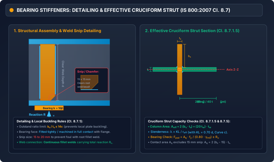
To prevent local buckling of the stiffener plates, the outstand width from the face of the web must satisfy:
Where . In addition, should fit within the flange overhang:
2. Effective Cruciform Column Section (Cl. 8.7.1.5):
The bearing stiffener pair acts compositely with an effective length of the beam web to form a cruciform compression column:
- At End Support: Web contributes a length of (measured from centerline of stiffeners towards the span).
- Under Interior Point Load: Web contributes on EACH side (total web length ).
3. Moment of Inertia and Buckling Capacity of Cruciform Strut:
The moment of inertia about the web centerline (axis of buckling) is:
Using Buckling Curve c, design compressive capacity is:
4. Bearing Check at Contact Face with Flange (Cl. 8.7.5.2):
The ends of bearing stiffeners are machined to bear tightly against the loaded flange. To clear the web-to-flange weld bead or root radius, stiffeners are chamfered/snipped by at corners. Net bearing contact area:
The design bearing capacity is:
5. Connection to Web (Cl. 8.7.5.3):
The stiffeners must be connected to the web by continuous fillet welds designed to transfer the full applied reaction :
3. Visual Diagrams & Structural Behavior
Figure 1: Dispersion Geometries & Failure Modes: Web Crippling vs Web Buckling
The following diagram contrasts the root dispersion of web crippling with the neutral-axis dispersion of web buckling.
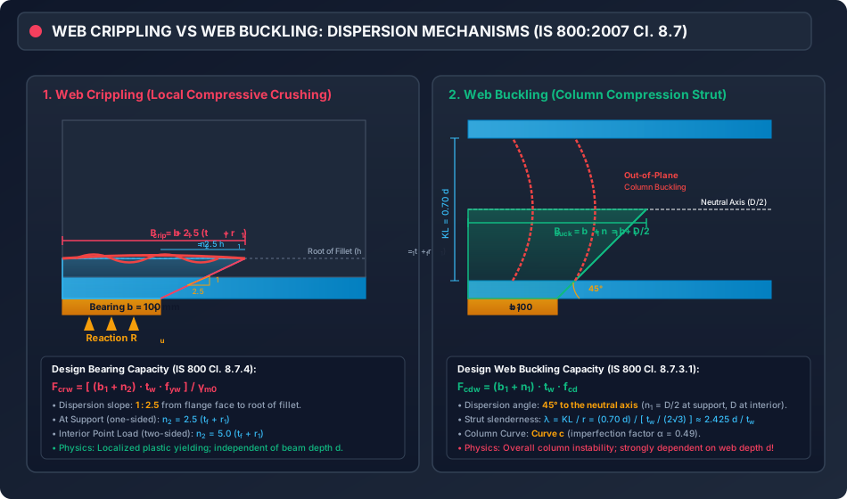
Figure 2: Bearing Stiffener Detailing & Effective Cruciform Strut
The figure below depicts the structural detailing of bearing stiffeners, weld snip clearances, and the effective cruciform compression column cross-section.
4. Mathematical Formulations & Design Procedures
+---------------------------------------------------------------------------------+
|            FLOWCHART: WEB CRIPPLING, BUCKLING & STIFFENER VERIFICATION          |
+---------------------------------------------------------------------------------+
                                         |
                                         v
                         [ Step 1: Input Beam & Load Data ]
                         Reaction / Point Load: F ; Bearing length: b1
                         Section: D, bf, tf, tw, r1, d = D - 2(tf + r1)
                                         |
                                         v
                         [ Step 2: Web Crippling Check ]
                         End Support:      n2 = 2.5 (tf + r1)
                         Interior Load:    n2 = 5.0 (tf + r1)
                         Fcrw = [ (b1 + n2) * tw * fyw ] / gm0
                                         |
                                  F <= Fcrw ?
                                 /           \
                            (YES)             (NO: Crippling Fails!)
                             /                   |
                            v                    |
                 [ Step 3: Web Buckling Check ]  |
                 End Support:   n1 = D / 2       |
                 Interior Load: n1 = D           |
                 B_buck = b1 + n1                |
                 KL = 0.70 d ; r = tw / (2*sqrt(3))
                 lambda = KL / r                 |
                 f_cd from Curve c (alpha = 0.49)|
                 Fcdw = B_buck * tw * f_cd       |
                            |                    |
                     F <= Fcdw ?                 |
                    /           \                |
               (YES)             (NO: Buckling)  |
                /                     \          |
               v                       v         v
     [ SAFE WITHOUT STIFFENERS ]     [ PROVIDE BEARING STIFFENERS ]
                                     1. Select bs <= (bf - tw)/2, ts >= bs / 14
                                     2. Form Cruciform Section:
                                        End: Aeff = 2(bs*ts) + 20 tw^2
                                        Int: Aeff = 2(bs*ts) + 40 tw^2
                                     3. Check column buckling: Pcd = Aeff * fcd >= F
                                     4. Check bearing: Fpsd = Aq * fy / (0.8 gm0) >= F
                                     5. Design 4 lines of web fillet welds
5. Solved Numerical Examples
Problem 1: Complete Web Buckling & Crippling Verification at End Support
Statement:
An ISMB 450 @ 72.4 kg/m beam transmits a factored end reaction to a concrete support pedestal through a steel bearing plate of length . Steel grade is E250 (, , ).
Section dimensions:
- Overall depth
- Flange width
- Flange thickness
- Web thickness
- Root radius
Verify whether the unstiffened beam web is adequate against web crippling and web buckling in accordance with IS 800:2007.
Solution:
Step 1: Section Parameters
- Distance from outer flange face to root of fillet:
- Clear web depth between root fillets:
Step 2: Web Crippling Verification (IS 800:2007 Cl. 8.7.4) At an end support, load disperses on one side only at a slope of :
Effective bearing length at the root of the fillet:
Design crippling resistance:
Check adequacy:
Step 3: Web Buckling Verification (IS 800:2007 Cl. 8.7.3.1) At an end support, the load disperses at to the neutral axis ():
Effective width of web column strut:
Effective strut cross-sectional area:
Effective length of web column (flanges restrained against rotation):
Radius of gyration:
Slenderness ratio of web strut:
Design compressive stress from Perry-Robertson formula (Buckling Curve c, ):
- Euler critical stress:
- Non-dimensional slenderness:
- Stress reduction factor:
- Design compressive stress:
Design web buckling resistance:
Check adequacy:
Conclusion: The unstiffened web of ISMB 450 is SAFE against both web crippling and web buckling. No bearing stiffeners are required.
Problem 2: Interior Concentrated Load: Failure Investigation & Minimum Bearing Length
Statement:
An ISLB 400 @ 56.9 kg/m beam (, , , , , , , ) supports an interior concentrated factored column load . The column transfers load through a base plate currently provided with a bearing length .
- Investigate the adequacy of the unstiffened web.
- If inadequate, compute the minimum stiff bearing length required to avoid providing bearing stiffeners.
Solution:
Step 1: Check Web Crippling under Interior Load Under an interior load, dispersion occurs on both sides:
Design crippling resistance:
Comparison:
Step 2: Check Web Buckling under Interior Load Dispersion occurs on both sides to the neutral axis ():
Slenderness calculation:
For on Curve c ():
Design web buckling capacity:
Comparison:
Step 3: Minimum Bearing Length () Calculation To make the unstiffened web safe without stiffeners, both conditions must be met:
-
For Web Crippling:
-
For Web Buckling:
Conclusion:
To prevent both web crippling and web buckling without providing stiffeners, the bearing plate length must be increased from to at least (governed by web buckling). If space restricts , bearing stiffeners must be provided.
Problem 3: Complete Design of Load-Carrying Bearing Stiffeners
Statement:
A welded plate girder with clear web depth , web thickness , and flange plates carries a factored end reaction . Steel grade is E250 (, , ).
Design a pair of flat plates as end bearing stiffeners, verifying:
- Local buckling limit of stiffener plates.
- Buckling capacity of the effective cruciform compression column.
- Bearing resistance at the flange contact face.
- Fillet weld connection to the web.
Solution:
Step 1: Stiffener Geometry Selection
- Available width under the flange: Adopt stiffener outstand width: .
- Thickness requirement to prevent local plate buckling (Table 2): Adopt stiffener plate thickness: .
Step 2: Effective Cruciform Strut Section Properties (Cl. 8.7.1.5) At an end support, the length of web contributing to the strut is :
Total effective cross-sectional area:
Moment of inertia about the web centerline ( axis):
- Distance from web centerline to centroid of each stiffener plate:
- Stiffener contribution:
- Web contribution:
- Total moment of inertia:
Radius of gyration:
Step 3: Column Buckling Capacity Check Effective strut length:
Slenderness ratio:
Since , column buckling is fully suppressed (pure yielding governs!):
Design buckling capacity of cruciform column:
Adequacy:
Step 4: Bearing Check at Contact Face with Flange (Cl. 8.7.5.2) Provide corner snips to clear the flange-to-web weld bead. Net bearing contact area:
Design bearing resistance:
Adequacy:
Step 5: Design of Fillet Weld Connection to Web The stiffener pair is connected to the web by 4 lines of continuous fillet weld along the clear depth . Net weld length per line (excluding two end snips of ):
Total effective weld length:
Provide a fillet weld:
- Throat thickness:
- Design shear capacity of weld:
- Applied shear stress on weld:
Adequacy:
6. Comparative Engineering Analysis
| Attribute / Parameter | Web Crippling (Bearing Crushing) | Web Buckling (Column Strut Instability) |
|---|---|---|
| Governing Code Clause | IS 800:2007 Cl. 8.7.4 | IS 800:2007 Cl. 8.7.3.1 |
| Physical Failure Mode | Localized compressive yielding / accordion crushing at root fillet | Lateral out-of-plane column buckling across web depth |
| Load Dispersion Slope | (1 vertical to 2.5 horizontal) | () |
| Dispersion Target Depth | Root of fillet: | Neutral axis: depth |
| Spread Length () at Support | ||
| Spread Length () at Interior | ||
| Dependence on Beam Depth | Independent of (pure local effect) | Heavily dependent on () |
| Strut Slenderness & Curve | Not applicable (pure bearing stress) | with , Curve c |
| Primary Remedy | Increase bearing length , increase , or bearing stiffener | Provide vertical load-carrying / bearing stiffeners |
7. Design Pitfalls & Practical Field Considerations
-
Confusion Between and Dispersion Angles:
Candidates and young engineers frequently swap the dispersion angles:- Web Crippling uses through the flange and root fillet.
- Web Buckling uses to the neutral axis.
Swapping these yields drastically erroneous effective bearing widths and non-conservative results.
-
Neglecting the Root Radius in Rolled Sections:
In rolled I-beams, the distance from flange face to the root of fillet is . Omitting reduces the calculated crippling resistance by —which can be up to of the section capacity! -
Ignoring Weld Bead Clearance (The Snip Rule):
Bearing stiffeners must never touch the web-to-flange fillet weld. Fabricators must clip the stiffener corners by at least (or ). Failing to detail this snip causes the stiffener to ride on the weld bead, creating severe stress concentrations and preventing tight bearing contact with the flange. -
Interior vs Support Dispersion Factors:
At an end support, load disperses into the span on one side only. Under an interior concentrated load, load disperses symmetrically on both sides. Using the interior multiplier ( or ) at an end support is a critical non-conservative design error.
8. Summary of Critical Formulae
========================================================================================
                      IS 800:2007 WEB CRIPPLING & BUCKLING CHEAT SHEET
========================================================================================
• Web Crippling Resistance (Cl. 8.7.4):
    Fcrw = [ (b1 + n2) * tw * fyw ] / gm0
    Support:   n2 = 2.5 (tf + r1)
    Interior:  n2 = 5.0 (tf + r1)

• Web Buckling Resistance (Cl. 8.7.3.1):
    Fcdw = (b1 + n1) * tw * fcd
    Support:   n1 = D / 2
    Interior:  n1 = D
    Effective Length:  KL = 0.70 d  (where d = D - 2(tf + r1))
    Radius of Gyration: r = tw / (2 * sqrt(3))
    Slenderness: lambda = KL / r ≈ 2.425 (d / tw)
    Column Curve: Curve c (alpha = 0.49)

• Stiffener Local Buckling Limit (Table 2):
    bs / ts <= 14 epsilon

• Effective Cruciform Stiffener Section (Cl. 8.7.1.5):
    End Support:      Aeff = 2(bs * ts) + 20 tw^2
    Interior Load:    Aeff = 2(bs * ts) + 40 tw^2

• Bearing Check at Flange Contact (Cl. 8.7.5.2):
    Fpsd = [ Aq * fy ] / [ 0.80 * gm0 ] >= Fapplied
    where Aq = 2 (bs - snip) * ts
========================================================================================
9. Exam Traps & Tricks
-
The Dispersion Slope Question:
Question: "In IS 800:2007, web crippling dispersion slope is taken as:"
Options: (A) (B) (C) (D)
Trap: Option (D) mixes units. The correct code value is (Option C). -
Depth Dependence Trap:
Question: "Which failure mode depends directly on the clear depth of the beam web ?"
Answer: Web Buckling. Web crippling depends only on and , not on . -
Effective Length of Web Strut:
In GATE CE, the effective length of the web column strut for restrained flanges is strictly , where is the clear depth between fillets (NOT the overall depth ). -
Web Length in Stiffener Strut:
Question: "What length of web acts with an end bearing stiffener?"
Answer: Exactly . For an intermediate stiffener under an interior load, it is .
10. Recommended Indian Standard Codes & Textbooks
- IS 800:2007: General Construction in Steel — Code of Practice, Bureau of Indian Standards, New Delhi. (Sections 8.7.1 through 8.7.5).
- Subramanian, N.: Design of Steel Structures (Limit State Method), Oxford University Press.
- Duggal, S.K.: Limit State Design of Steel Structures, McGraw Hill Education.
- Bhavikatti, S.S.: Design of Steel Structures (IS: 800-2007), I.K. International Publishing House.
11. Practice Problems with Answer Keys
Problem 1 (GATE CE Objective)
A rolled steel I-section beam has , , , and . It rests on an end bearing plate of length . The design bearing strength of the web against crippling under IS 800:2007 is:
(A)
(B)
(C)
(D)
Answer: (B)
Hint: . . .
.
Problem 2 (UPSC ESE Objective)
In the design of bearing stiffeners for plate girders according to IS 800:2007, the outstand of the stiffener from the web face of thickness is limited to:
(A)
(B)
(C)
(D)
Answer: (B)
Hint: From Table 2 (Maximum Slenderness Ratios for Stiffeners to prevent local buckling).
Problem 3 (GATE CE Numerical Answer Type)
An ISMB 500 beam (, ) rests on an end support with . The effective width of the web acting as a column strut against web buckling (in ) is ______.
Answer: 370
Hint: At an end support, .
.
12. Cross-Topic Linkages & Forward References
- Preceding Topic: Topic 02: Shear Capacity & High Shear Interaction (STEEL-04-02) — Web shear stresses, unstiffened web buckling limit (), and interaction.
- Following Topic: Topic 04: Laterally Unsupported Beams & Lateral-Torsional Buckling (STEEL-04-04) — LTB critical moment, Perry-Robertson formulation for flexural compression, and Table 14/15 effective lengths.
- Forward Reference: Topic 03: Plate Girder Stiffeners & Splice Design (STEEL-05-03) — Comprehensive design of intermediate transverse, horizontal, and tension stiffeners.