Welded Connections (Fillet & Butt Welds, Sizing & Detailing — IS 800:2007)
In this chapter (4 topics)
On this page
- 1. Topic Title and Metadata
- 2. Prerequisites and Engineering Context
- 3. Fundamental Physical and Engineering Principles
- 3.1 Physics of Electric Arc Welding
- 3.2 Partial Safety Factors for Welds (γmw) per IS 800:2007 Table 5
- 3.3 Welded vs Bolted Connections: Engineering Trade-offs
- 4. Rigorous Mathematical Derivations & Code Formulations
- 4.1 Classification of Welded Joints & Welds
- 4.2 Fillet Weld Geometry and Throat Thickness Formulations (IS 800:2007 Cl. 10.5)
- 4.3 Sizing Boundaries for Fillet Welds (IS 800:2007 Cl. 10.5.2)
- 4.4 Effective Length of Fillet Weld (Le) (IS 800:2007 Cl. 10.5.4)
- 4.5 Design Strength Formulations (IS 800:2007 Cl. 10.5.7)
- 4.6 Balancing Fillet Welds for Asymmetrical Sections (e.g., Angle Struts & Ties)
- 5. Detailing Rules and Codal Mandates
- 6. SVG Diagrams and Visual Explanations
- 6.1 Welded Joint Types, Throat Thickness & Fusion Geometry
- 6.2 Fillet Weld Stress Profiles & Codal Sizing Rules
- 7. Solved Numerical Examples
- 7.1 Example 1: Design of a Welded Lap Joint for a Tie Flat
- 7.2 Example 2: Balanced Welded Connection for an Angle Tension Member
- 7.3 Example 3: Full Penetration (CJP) vs Partial Penetration (PJP) Groove Welds
- 8. Common Pitfalls, Misconceptions, and Examination Traps
- 9. Comparative Analysis and Summary Tables
- 9.1 Fillet Welds vs Butt (Groove) Welds
- 9.2 Minimum Weld Size Sizing Rules (IS 800:2007 Table 21)
- 10. Exam-Specific Focus and Formula Cheat Sheet
- 10.1 Must-Remember Formulas for Quick Objective Calculations
- 11. Practice Problems and Self-Assessment with Numerical Answers
- 12. Standard References and Further Reading
1. Topic Title and Metadata
| Attribute | Specification |
|---|---|
| Topic ID | STEEL-01-02 |
| Module / Subject | Subject 06: Design of Steel Structures (IS 800:2007) |
| Chapter | Chapter 01: Structural Steel Fundamentals & Connection Design |
| Topic Title | Welded Connections (Fillet Welds, Groove/Butt Welds, Throat Thickness, Sizing & Detailing) |
| Applicable Standards | IS 800:2007 (Section 10: Connections), IS 816:1969, IS 9595:1996, AWS D1.1/D1.1M, Eurocode 3 (EN 1993-1-8) |
| Target Examinations | GATE CE, UPSC ESE (Paper-I), SSC JE, State PSC AE/JE, RRB JE |
| Primary Authorship | Civil Engineering Autonomous Master Repository |
| Verification Gate | Level 1 through Level 7 (Mathematical Recalculation, Codal Compliance, SVG Validation) |
2. Prerequisites and Engineering Context
Prior to analyzing and designing welded connections, students and design engineers must be well-grounded in:
- Mechanics of Materials (
SOM-01-01,SOM-05-01): Direct and complementary shear stresses, principal stresses, and equilibrium across inclined planes. - Structural Steel Metallurgy (
SOM-01-02,STEEL-01-01): Elastic modulus (), yield strength (), ultimate strength (), and partial safety factors (, ). - Failure Theories (
SOM-02-05): The von Mises distortion energy yield criterion ().
While bolted connections dominate site erection due to their speed and weather tolerance, welded connections are the preeminent joining method in modern steel fabrication shops. Welding produces monolithic, rigid structural joints with zero slip, offering significant savings in steel weight (eliminating heavy gusset plates, splice plates, and fastener shanks). However, the extreme thermal cycling involved in welding introduces localized metallurgical changes, residual tensile stresses, and potential distortion that demand rigorous codal sizing and inspection protocols.
3. Fundamental Physical and Engineering Principles
3.1 Physics of Electric Arc Welding
Welding achieves the structural coalescence of steel components by heating the joint interface above the melting point of steel () using an electric arc established between an electrode and the workpiece.
       [ Electrode Holder / Shielding Gas ]
                    |
                    v (Consumable Electrode)
             ===== ARC =====
             ~ ~ ~ ~ ~ ~ ~ ~  (Molten Slag Pool)
    [ Base Metal ] \       / [ Base Metal ]
                    \     /
                 [ FUSION ZONE ]
                 [ HAZ ZONE   ]
A completed weld joint exhibits three distinct microstructural zones:
- Weld Metal (Fusion Zone): A mixture of parent steel and filler wire that solidifies from the liquid phase into a cast dendritic structure. It generally possesses higher yield strength than the parent metal due to alloying elements.
- Heat-Affected Zone (HAZ): The adjacent base metal that did not melt but underwent solid-state phase transformation (grain growth, recrystallization, and martensitic quenching). The HAZ is often the most critical region susceptible to cold cracking and embrittlement if cooling rates are excessively high.
- Parent Metal: Unaffected base steel retaining its original rolled grain structure.
3.2 Partial Safety Factors for Welds () per IS 800:2007 Table 5
The quality and reliability of welded joints depend directly on environmental control and workmanship during deposit:
Key Takeaway: Site welds are penalized with a strength reduction compared to factory shop welds () to account for adverse wind conditions, humidity, awkward welding positions, and variable operator fatigue on site.
3.3 Welded vs Bolted Connections: Engineering Trade-offs
| Engineering Parameter | Welded Connections | Bolted Connections |
|---|---|---|
| Structural Weight | Lighter ( saving; no splice plates or gussets) | Heavier (requires overlapping plies and cover plates) |
| Gross Section Efficiency | Up to (no deduction for bolt holes) | Reduced ( due to net hole deduction) |
| Joint Rigidity | Truly monolithic and rigid (continuous frame behavior) | Semi-rigid to flexible (initial slip in bearing bolts) |
| Aesthetic Appearance | Clean, neat, architectural profile | Protruding bolt heads, nuts, and washer plates |
| Airtightness / Watertightness | 100% sealed (ideal for tanks, pressure vessels, pipes) | Prone to micro-leakage unless caulked or gasketed |
| Inspection & Quality Control | Demands specialized NDE (Ultrasonic, Radiographic, DPT) | Simple visual verification of torque and snugness |
| Residual Stresses & Fatigue | High residual tensile stresses; sensitive to fatigue | Minimal residual thermal stresses; HSFG excels in fatigue |
4. Rigorous Mathematical Derivations & Code Formulations
4.1 Classification of Welded Joints & Welds
1. Butt / Groove Welds
Formed by depositing weld metal into a prepared groove between two coplanar plates abutting end-to-end.
- Complete Joint Penetration (CJP): Weld metal fully penetrates and fuses across the entire thickness of the joint.
- Partial Joint Penetration (PJP): Weld depth is less than the plate thickness, leaving an unfused root notch.
2. Fillet Welds
Formed by depositing a triangular prism of weld metal in the corner formed by two overlapping or intersecting plates (lap joints, tee joints, corner joints).
- Transverse Fillet Weld: Weld axis is oriented perpendicular to the direction of applied tensile or compressive load.
- Longitudinal (Side) Fillet Weld: Weld axis is oriented parallel to the direction of applied load.
4.2 Fillet Weld Geometry and Throat Thickness Formulations (IS 800:2007 Cl. 10.5)
                       |<- Leg s ->|
                     --+-----------+
                     ^ |           |
                     | |           | (Vertical Plate)
                     | |           |
                     s |      . '  |
                     | |   . ' t_t |
                     v |. '        |
                     --+-----------+----------------
                       |<-- Leg s ->| (Horizontal Base)
4.2.1 Leg Size ()
The leg size is the side dimension of the largest right-angled isosceles triangle that can be inscribed within the weld cross-section.
4.2.2 Effective Throat Thickness () (IS 800:2007 Cl. 10.5.3)
The effective throat thickness is the shortest distance from the root of the weld to the hypotenuse of the inscribed right triangle:
where is a constant factor depending on the angle between the fusion faces, given in IS 800:2007 Table 22:
| Angle Between Fusion Faces () | Constant | Theoretical Throat Thickness |
|---|---|---|
Critical Codal Mandate:
Fillet welds with fusion face angles less than or greater than must NOT be relied upon to transmit structural loads unless verified by special qualification testing.
Minimum Throat Thickness: The effective throat thickness shall NOT be less than .
4.3 Sizing Boundaries for Fillet Welds (IS 800:2007 Cl. 10.5.2)
4.3.1 Minimum Leg Size () (Table 21)
To avoid rapid thermal quenching, excessive hardening of the heat-affected zone, and cold cracking, the minimum leg size of a fillet weld is governed by the thickness of the thicker connected plate:
| Thickness of Thicker Connected Part () | Minimum Size of First Run / Single Run Fillet Weld () |
|---|---|
| Up to | |
| Over up to | |
| Over up to | |
| Over up to | |
| Over |
Exception: If the minimum size exceeds the thickness of the thinner part, the weld size may be taken equal to the thickness of the thinner part provided adequate preheat is maintained.
4.3.2 Maximum Leg Size ()
To prevent burning away of plate corners and ensure a clearly defined edge for inspection:
- For Square Edges of Plates:
- For Rounded Toes of Rolled Sections (Flanges of Channels, Angles, Beams):
4.4 Effective Length of Fillet Weld () (IS 800:2007 Cl. 10.5.4)
At the start and termination of a weld run, localized craters and poor fusion occur. To account for this end defect, the effective length () is obtained by deducting twice the weld size from the overall physical length ():
- Minimum Effective Length: To ensure predictable load distribution, the effective length of a fillet weld must not be less than four times the leg size: (If the physical length is shorter than , the design size shall be taken as ).
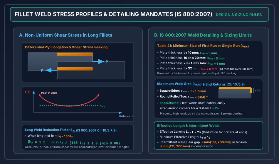
4.4.3 Long Weld Reduction Factor () (Cl. 10.5.7.3)
When a longitudinal side fillet weld extends over an exceptionally long joint (), differential longitudinal strains between the connected plies cause high shear stress concentrations at both ends while the center remains understressed. The design capacity must be downgraded by the reduction factor :
where is the overall length of the weld along the load direction.
4.5 Design Strength Formulations (IS 800:2007 Cl. 10.5.7)
4.5.1 Fillet Weld Design Shear Capacity
Because the minimum throat area represents the weakest shearing plane, all fillet welds (transverse and longitudinal) are designed on the basis of shear stress on the effective throat area:
where:
- = Smaller of the ultimate tensile strength of the parent steel ( for Fe 410) and the weld electrode ( for standard E41/E43 electrodes).
- = Ultimate shear strength per von Mises yield criterion.
- = Partial safety factor for weld ( for shop welds, for field welds).
For standard Fe 410 steel in a factory fabrication shop ():
Design Capacity per Unit Length ( in N/mm or kN/mm):
For a standard fillet weld ():
Total Design Shear Capacity of Welded Joint ():
4.5.2 Complete Joint Penetration (CJP) Butt Weld Capacity (Cl. 10.5.7.1.1)
A full-penetration butt weld is treated as equivalent to the parent metal:
- In Tension or Compression: where .
- In Shear:
4.5.3 Partial Joint Penetration (PJP) Butt Weld Capacity (Cl. 10.5.7.1.2)
- Effective throat thickness is taken as:
- The weld is designed for shear using the weld material strength:
4.6 Balancing Fillet Welds for Asymmetrical Sections (e.g., Angle Struts & Ties)
When an unsymmetrical angle section (ISA) is welded to a gusset plate, the line of action of the axial tensile force passes through the centroid (CG) of the angle. If equal weld lengths are placed at the heel and toe, an internal eccentric moment is induced, causing out-of-plane twisting and premature tear-out.
                  +------------------------------------------+
                  |                                          |
        Heel weld |================== L_1 ===================|
                  |                                          |
      -- CG Axis  - - - - - - - - - - - - - - - - - - - - - -+ ----> P_u
                  |                                          |
                  |           ISA Angle Section              |
                  |                                          |
         Toe weld |======== L_2 ========|                   |
                  +------------------------------------------+
To achieve purely axial load transfer with zero eccentric moment:
- Let = Distance from the heel of the angle to its centroidal axis (CG).
- Let = Distance from the toe of the angle to its centroidal axis (CG) ().
- Total required effective length:
- Taking moments of weld resistance about the line of action of the load (the CG axis):
- Solving simultaneously:
Engineering Rule: Because the heel is closer to the centroid (), the heel weld must be significantly longer than the toe weld ().
5. Detailing Rules and Codal Mandates
- End Returns (IS 800:2007 Cl. 10.5.8.3): Fillet welds terminating at the ends or sides of parts must be returned continuously around the corner in the same plane for a distance not less than twice the weld size (). This detailing arrests localized peel stresses and prevents notch tearing under bending fluctuations.
- Minimum Overlap in Lap Joints (Cl. 10.5.1.2): The minimum lap distance between connected plates must not be less than four times the thickness of the thinner part () or , whichever is greater.
- Longitudinal Side Fillets Spacing (Cl. 10.5.7.3): When only longitudinal fillet welds along edges are provided to transmit load, the perpendicular distance between them () must not exceed (to prevent shear lag buckling of the plate center). Moreover, the length of each side fillet weld must not be less than the transverse distance between them ().
- Intermittent Fillet Welds (Cl. 10.5.5):
- Minimum length of clear stitch: or (whichever is greater).
- Maximum clear spacing between weld segments:
- In tension: .
- In compression: .
- Non-Destructive Examination (NDE) Quality Levels:
- Visual Testing (VT): 100% inspection for undercuts, overlap, surface porosity, and throat dimensions.
- Dye Penetrant Testing (DPT): Detects surface-breaking micro-cracks in root and toe zones.
- Magnetic Particle Testing (MPT): Reveals near-surface sub-surface discontinuities in ferromagnetic steels.
- Ultrasonic Testing (UT) & Radiographic Testing (RT): Mandatory for full-penetration CJP groove welds in dynamic bridge girders to confirm zero internal slag inclusion or lack of fusion.
6. SVG Diagrams and Visual Explanations
6.1 Welded Joint Types, Throat Thickness & Fusion Geometry
The following original diagram details the fundamental anatomy of a fillet weld (root, toe, leg size , effective throat ), presents the codal table of factors vs fusion face angles, and contrasts Complete Joint Penetration (CJP) with Partial Joint Penetration (PJP) groove welds.

6.2 Fillet Weld Stress Profiles & Codal Sizing Rules
The following diagram illustrates the differential shear stress distribution along longitudinal side fillets, the long weld reduction factor , minimum and maximum sizing boundaries, and mandatory corner end returns.
7. Solved Numerical Examples
7.1 Example 1: Design of a Welded Lap Joint for a Tie Flat
Problem Statement:
A structural tie member consisting of a flat wide and thick is to be connected to a thick gusset plate to carry a factored tensile load . Steel grade is Fe 410 (). Design a shop-welded fillet joint () using E41 electrodes.
- Determine the minimum and maximum permissible weld sizes and select a suitable size .
- Compute the design shear strength of the weld per unit length.
- Calculate the required effective length and determine the detailing dimensions for side fillet welds.
Step-by-Step Solution:
-
Step 1: Permissible Weld Sizing (IS 800:2007 Cl. 10.5.2)
- Minimum weld size (): Governed by the thicker part (). From Table 21:
- Maximum weld size (): Governed by the square edge of the thinner plate ():
- Adopt standard fillet weld size:
-
Step 2: Effective Throat Thickness & Strength per Unit Length
- Fusion face angle is .
- Design shear stress of weld (IS 800 Cl. 10.5.7.1.1):
- Strength per unit length:
-
Step 3: Effective Weld Length & Detailing
- Total effective length required:
- Arrangement: Longitudinal Side Fillets Only:
- Provide weld equally along the two longitudinal edges:
- Total physical length per side (adding end defect allowance ):
- Check transverse spacing rule: Distance between welds .
and . - Provide continuous end returns of length around the corners.
7.2 Example 2: Balanced Welded Connection for an Angle Tension Member
Problem Statement:
An unequal angle tension member ISA (Fe 410 steel) is to be welded with its longer leg () to a thick gusset plate. The member carries a factored axial tensile load . The distance from the outer heel of the angle to its center of gravity is . Using a shop fillet weld, determine the required effective weld lengths at the heel and toe to completely eliminate internal bending eccentricity.
Step-by-Step Solution:
-
Step 1: Sizing Verification for
- Minimum size for gusset: .
- Maximum size at square heel of leg: .
- Maximum size at rounded rolled toe: .
- Thus, is valid across both edges.
-
Step 2: Total Effective Length Required
- Throat thickness: .
- Strength per unit length: .
- Total effective length:
-
Step 3: Moment Equilibrium to Eliminate Eccentricity
- Distance from CG to heel: .
- Distance from CG to toe: .
- Total depth .
- Let = effective weld length at the heel; = effective weld length at the toe.
- Setting the net moment about the CG axis to zero:
-
Step 4: Physical Detailing Lengths
- At Heel: Physical length (plus end return).
- At Toe: Physical length (plus end return).
7.3 Example 3: Full Penetration (CJP) vs Partial Penetration (PJP) Groove Welds
Problem Statement:
Two plates of width and thickness of Fe 410 steel () are butt-welded in a shop environment (). Compare the design tensile capacity of:
- A Complete Joint Penetration (CJP) Single-V butt weld with run-on and run-off plates.
- A Partial Joint Penetration (PJP) butt weld without back gouging ().
Step-by-Step Solution:
-
Step 1: Complete Joint Penetration (CJP) Butt Weld Capacity
- Run-on and run-off plates ensure full effective length across the entire width: .
- Full penetration ensures effective throat thickness equals plate thickness: .
- Effective area: .
- Per IS 800:2007 Cl. 10.5.7.1.1, CJP butt welds are treated as parent metal yielding in tension:
-
Step 2: Partial Joint Penetration (PJP) Butt Weld Capacity
- Effective throat thickness (IS 800 Cl. 10.5.3.3):
- Effective throat area:
- Per IS 800 Cl. 10.5.7.1.2, PJP groove welds are governed by weld shear strength across the throat:
-
Step 3: Comparative Ratio
Conclusion: Providing full penetration (CJP) nearly doubles the load capacity () and completely eliminates the unfused root notch that causes fatigue cracking under dynamic service loads.
8. Common Pitfalls, Misconceptions, and Examination Traps
- Using Thinner Plate Thickness for Minimum Weld Size ():
- Trap: Looking at the thinner connected plate to look up Table 21.
- Reality: is strictly governed by the thickness of the thicker part (). A heavy plate acts as a massive thermal heat sink, causing rapid chilling and brittle cracking if a tiny weld bead is deposited.
- Confusing Maximum Size for Square vs Rounded Edges:
- Trap: Subtracting from the flange toe of a rolled channel or I-section.
- Reality: applies exclusively to square sheared/rolled edges. For rounded toes of rolled shapes, .
- Omitting the Crater Deduction ():
- Trap: Believing effective length equals physical length ().
- Reality: Unless run-on and run-off extension tabs are provided, must always be subtracted ().
- Equal Weld Lengths on Asymmetric Angles:
- Trap: Providing equal weld lengths at the heel and toe of an angle tension member.
- Reality: Equal welds induce severe eccentricity, secondary bending, and prying tearing. The weld must be balanced in inverse proportion to the centroidal distances (), making the heel weld substantially longer.
- Applying Tensile Yield Formula to Fillet Welds:
- Trap: Calculating fillet weld strength using .
- Reality: All fillet welds fail in shear across the minimum throat plane and MUST be evaluated using the shear capacity .
9. Comparative Analysis and Summary Tables
9.1 Fillet Welds vs Butt (Groove) Welds
| Parameter | Fillet Welds | Butt (Groove) Welds |
|---|---|---|
| Edge Preparation | None required (economical square cuts) | Beveling, V, or U groove machining required |
| Stress Flow | Indirect, turns at right angles; high shear concentration | Direct, continuous, in-line stress trajectories |
| Critical Failure Plane | Always shear on the effective throat () | Tension, compression, or shear on plate cross-section |
| Design Strength | Equal to parent plate () for CJP | |
| Fatigue Performance | Moderate to poor (root notch acts as stress raiser) | Superior (smooth transition when ground flush) |
9.2 Minimum Weld Size Sizing Rules (IS 800:2007 Table 21)
| Thicker Plate Thickness | Minimum Leg Size () | Typical Application |
|---|---|---|
| Light truss web members, purlin cleats | ||
| Standard beam-column frames, gusset plates | ||
| Heavy industrial crane columns, bridge girders | ||
| (first run) | Base plates, heavy transfer trusses, offshore jackets |
10. Exam-Specific Focus and Formula Cheat Sheet
10.1 Must-Remember Formulas for Quick Objective Calculations
11. Practice Problems and Self-Assessment with Numerical Answers
-
Practice Problem 1: A thick flat is welded to a thick bracket plate using an fillet weld. Is the selected weld size codally acceptable? Compute the design strength per millimeter run for field welding (, Fe 410 steel).
Answer: Table 21: (for ); . Selected is acceptable (). Throat . . . -
Practice Problem 2: An ISA angle with (along longer leg) is connected to a gusset plate to resist a factored load . A shop fillet weld is provided (). Calculate the required effective weld lengths at the heel and toe for balanced load transfer.
Answer: Total . . Heel length (say ). Toe length (say ). -
Practice Problem 3: A longitudinal side fillet weld connecting a cover plate has an overall length . The weld size is (). Determine if the long weld reduction factor applies, and compute its value.
Answer: Threshold limit . Since , reduction applies. .
12. Standard References and Further Reading
- IS 800:2007: General Construction in Steel — Code of Practice (Third Revision), Bureau of Indian Standards, New Delhi. (Section 10: Connections, Clauses 10.5.1 to 10.5.8).
- IS 816:1969: Code of Practice for Use of Metal Arc Welding for General Construction in Mild Steel, BIS, New Delhi.
- Subramanian, N.: Design of Steel Structures, Oxford University Press. (Chapter 6: Welded Connections).
- Duggal, S.K.: Limit State Design of Steel Structures, McGraw Hill Education. (Chapter 6: Welded Connections).
- AWS D1.1/D1.1M: Structural Welding Code — Steel, American Welding Society.