Laterally Unsupported Beams & Lateral-Torsional Buckling
In this chapter (4 topics)
On this page
- 1. Topic Overview & Engineering Significance
- 2. Code Provisions & Theoretical Derivations
- 2.1 Mechanics & Governing Differential Equation of LTB
- 2.2 IS 800:2007 Formulation for Mcr (Cl. 8.2.2.1)
- 2.3 Non-Dimensional Slenderness for LTB (λLT)
- 2.4 Design Bending Compressive Stress (fbd) (Cl. 8.2.2)
- 2.5 Effective Length (LLT) & Loading Conditions (IS 800:2007 Table 15)
- 3. Visual Diagrams & Structural Behavior
- Figure 1: Lateral-Torsional Buckling Deformation & Kinematic Couples
- Figure 2: LTB Design Reduction Factor (χLT) Curves & Table 15 Restraints
- 4. Mathematical Formulations & Design Procedures
- 5. Solved Numerical Examples
- Problem 1: Complete LTB Analysis of a Simply Supported Beam
- Problem 2: Effect of Intermediate Lateral Bracing Spacing
- Problem 3: Destabilizing vs Normal Loading on a Welded Plate Girder
- 6. Comparative Engineering Analysis
- 7. Design Pitfalls & Practical Field Considerations
- 8. Summary of Critical Formulae
- 9. Exam Traps & Tricks
- 10. Recommended Indian Standard Codes & Textbooks
- 11. Practice Problems with Answer Keys
- Problem 1 (GATE CE Objective)
- Problem 2 (UPSC ESE Objective)
- Problem 3 (GATE CE Numerical Answer Type)
- 12. Cross-Topic Linkages & Forward References
1. Topic Overview & Engineering Significance
In structural steel framing, when a beam is subjected to major-axis bending without continuous or sufficiently close intermediate lateral restraint to its compression flange, the beam is classified as a Laterally Unsupported Beam. Under this condition, the member cannot attain its full plastic moment capacity (). Instead, failure is triggered by a coupled spatial instability phenomenon known as Lateral-Torsional Buckling (LTB).
During flexure:
- The compression flange behaves as an axially loaded column subjected to high compressive stresses (). It tends to buckle sideways (lateral deflection along the minor axis).
- The tension flange is stabilized by tensile stresses and resists lateral movement.
- The web connects the two flanges and possesses finite torsional rigidity, forcing the cross-section to rotate / twist () about the shear center as the compression flange deflects sideways.
Under IS 800:2007 Cl. 8.2.2, the design bending strength is determined using a Perry-Robertson formulation adapted for flexural buckling. The design capacity depends on:
- The Elastic Critical Moment (), dictated by minor-axis bending stiffness (), St. Venant torsional rigidity (), and warping torsional rigidity ().
- The Non-Dimensional Slenderness for LTB ().
- The Effective Length for LTB (), incorporating support torsional and warping restraints as well as loading height (normal vs destabilizing gravity loading on the top flange per Table 15).
Mastery of LTB mechanics, effective length evaluation, and code reduction curves is critical for designing crane gantry girders, industrial portal frame rafters, pipe-bridge walkways, and roof beams prior to the casting of composite slabs.
2. Code Provisions & Theoretical Derivations
2.1 Mechanics & Governing Differential Equation of LTB
Consider a doubly symmetric I-section beam of length subjected to a uniform bending moment about its major axis. If the beam deflects laterally by and twists by angle , the governing coupled differential equations of equilibrium are:
- Lateral Minor-Axis Bending:
- Torsional Equilibrium (St. Venant + Warping Torsion):
Differentiating the torsional equation and substituting , we obtain the fourth-order differential equation for twist :
For simply supported ends with fork restraints (torsionally restrained , but free to warp ), the lowest eigenvalue yields the classical Timoshenko-Vlasov Elastic Critical Moment ():
Where:
- is the Modulus of Elasticity.
- is the Shear Modulus ().
- is the minor-axis moment of inertia.
- is the St. Venant uniform torsion constant.
- is the warping torsion constant (for doubly symmetric I-sections with ).
2.2 IS 800:2007 Formulation for (Cl. 8.2.2.1)
In IS 800:2007, for doubly symmetric rolled I-sections and channels, the exact Timoshenko formula is expressed in a simplified standard format:
Where:
- is the effective length for lateral-torsional buckling (Table 15).
- is the radius of gyration about the minor axis.
- is the center-to-center distance between flanges.
- is the thickness of the compression flange.
(Notice the two distinct resisting components inside the square bracket: represents the warping torsion contribution, while the second term accounts for the St. Venant uniform torsional rigidity).
2.3 Non-Dimensional Slenderness for LTB ()
The non-dimensional lateral-torsional slenderness ratio is defined as:
Where:
- for Class 1 (Plastic) and Class 2 (Compact) cross-sections.
- for Class 3 (Semi-Compact) cross-sections.
- is the plastic section modulus about the major axis.
- is the characteristic yield strength of steel.
The LTB Plateau Limit ():
According to IS 800:2007 Cl. 8.2.2, if:
The member is sufficiently stocky that Lateral-Torsional Buckling is entirely suppressed!
The beam develops its full design plastic moment capacity without any reduction:
2.4 Design Bending Compressive Stress () (Cl. 8.2.2)
When , lateral-torsional instability reduces the available bending compressive strength. The design bending compressive stress is obtained from the Perry-Robertson formulation:
Where the lateral-torsional reduction factor is:
Imperfection Factor () Selection (Table 13a & 13b):
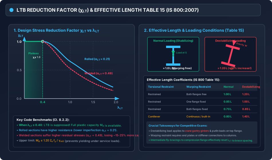
- Rolled I-Sections: (Buckling Curve a / b). Rolled sections possess relatively low residual cooling stresses at the flange tips.
- Welded I-Sections: (Buckling Curve c). Flame cutting and longitudinal fillet welding induce severe tensile residual stresses at the web-flange junction balanced by compressive residual stresses at the flange tips, accelerating premature lateral buckling.
Design Bending Strength ():
2.5 Effective Length () & Loading Conditions (IS 800:2007 Table 15)
The effective length depends on the restraint conditions at supports and the vertical position of the applied load:
1. End Torsional Restraint:
The beam ends must be prevented from rotating about their longitudinal axis (). This is typically achieved by web stiffeners, end-plate connections, or diaphragm bracing.
2. End Warping Restraint:
- Both Flanges Free to Warp: Standard end-cleat or simple shear connection ().
- One Flange Fixed against Warping: End connected to stiff column flange ().
- Both Flanges Fixed against Warping: Heavily stiffened moment connection ().
3. Normal vs Destabilizing Loading:
- Normal Loading: Loads applied at or below the shear center, or loads applied to the top flange where the load is restrained from moving sideways with the beam (e.g., concrete slab during casting).
- Destabilizing Loading: Gravity loads applied to the top compression flange that are free to tip and move laterally as the beam deflects (e.g., crane gantry wheel loads, purlins resting on top flange without roof diaphragm).
Destabilizing loading increases the effective length by approximately (), producing a severe reduction in moment capacity!
3. Visual Diagrams & Structural Behavior
Figure 1: Lateral-Torsional Buckling Deformation & Kinematic Couples
The following diagram illustrates the 3D deformation of an unbraced beam, showing top flange lateral translation , cross-sectional twist , and the restoring actions (, , ).
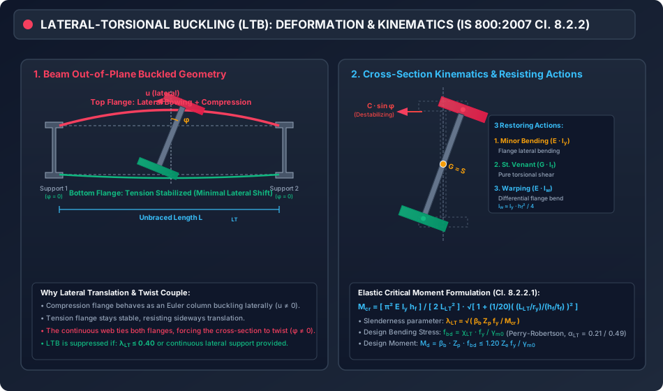
Figure 2: LTB Design Reduction Factor () Curves & Table 15 Restraints
The diagram below presents the non-dimensional design curves for rolled vs welded sections and details the Table 15 effective length factors for normal vs destabilizing loading.
4. Mathematical Formulations & Design Procedures
+---------------------------------------------------------------------------------+
|               COMPLETE IS 800:2007 LTB DESIGN ALGORITHM (Cl. 8.2.2)             |
+---------------------------------------------------------------------------------+
                                         |
                                         v
                         [ Step 1: Input Section & Span Data ]
                         Span L ; Cross-section: D, bf, tf, tw, Iy, ry, Ze, Zp
                         Steel grade: fy, gm0 = 1.10, E = 2e5 MPa
                                         |
                                         v
                     [ Step 2: Determine Effective Length L_LT ]
                     Evaluate Table 15 based on:
                     - Torsional restraint at ends (phi = 0)
                     - Warping restraint (free / partially fixed / fully fixed)
                     - Loading level: Normal (1.0 L) vs Destabilizing (1.20 L)
                                         |
                                         v
                   [ Step 3: Compute Elastic Critical Moment Mcr ]
                   hf = D - tf ; slend_y = L_LT / ry ; df_ratio = hf / tf
                   Mcr = [ pi^2 * E * Iy * hf ] / [ 2 * L_LT^2 ] *
                         sqrt[ 1 + (1/20) * ( slend_y / df_ratio )^2 ]
                                         |
                                         v
                 [ Step 4: Compute Non-Dimensional Slenderness ]
                             lambda_LT = sqrt( beta_b * Zp * fy / Mcr )
                                         |
                               lambda_LT <= 0.40 ?
                              /                  \
                         (YES)                    (NO)
                          /                          \
             [ LTB Fully Suppressed! ]      [ LTB Governs Capacity ]
             chi_LT = 1.0                   Select alpha_LT (0.21 rolled / 0.49 welded)
             fbd = fy / gm0                 phi_LT = 0.5 [ 1 + alpha_LT(lambda_LT - 0.2) + lambda_LT^2 ]
                                            chi_LT = 1 / [ phi_LT + sqrt(phi_LT^2 - lambda_LT^2) ]
                                            fbd = chi_LT * fy / gm0
                                         |
                                         v
                       [ Step 5: Design Bending Strength Md ]
                               Md = beta_b * Zp * fbd
                                         |
                                         v
                     [ Step 6: Apply Serviceability Yield Ceiling ]
                     Simply Supported:  Md <= 1.20 Ze * fy / gm0
                     Cantilever:        Md <= 1.50 Ze * fy / gm0
                                         |
                                         v
                       [ Step 7: Final Structural Verification ]
                                     M_applied <= Md
5. Solved Numerical Examples
Problem 1: Complete LTB Analysis of a Simply Supported Beam
Statement:
A rolled steel I-beam ISMB 400 @ 61.6 kg/m is used as a simply supported roof beam over a clear span . The compression flange is unrestrained against lateral displacement throughout the span. The beam ends are fully restrained against torsional rotation () but are free to warp. Loading is normal (applied at shear center). Steel grade is E250 (, , ).
Section properties for ISMB 400:
- Overall depth
- Flange width
- Flange thickness
- Web thickness
- Minor-axis moment of inertia
- Minor-axis radius of gyration
- Elastic section modulus
- Plastic section modulus
Calculate the design bending strength of the beam, and evaluate the percentage loss in capacity caused by lateral-torsional buckling.
Solution:
Step 1: Effective Length () From IS 800:2007 Table 15, for ends restrained against torsion, both flanges free to warp, and normal loading:
Step 2: Section Geometry Parameters
- Center-to-center distance between flanges:
- Minor-axis slenderness ratio:
- Ratio of flange distance to thickness:
Step 3: Elastic Critical Moment () Using the simplified formula of IS 800:2007 Cl. 8.2.2.1:
The elastic critical moment is:
Step 4: Non-Dimensional Slenderness () The section is Class 1 (Plastic), so :
Since , Lateral-Torsional Buckling governs!
Step 5: Design Bending Compressive Stress () For rolled I-sections, imperfection factor (Curve a / b):
Reduction factor :
Design bending stress:
Step 6: Design Moment Capacity ()
Check upper bound ceiling:
Since , the capacity is .
Step 7: Comparison with Laterally Supported Capacity If the beam were continuously laterally supported:
Capacity loss due to LTB:
Conclusion: Over a unbraced span, lateral-torsional buckling wipes out of the beam's moment capacity!
Problem 2: Effect of Intermediate Lateral Bracing Spacing
Statement:
For the same ISMB 400 beam spanning , evaluate the design moment capacity under three bracing configurations:
- Case A: Completely unbraced ().
- Case B: One central intermediate brace at midspan ().
- Case C: Two intermediate braces at third points ().
Solution Summary:
| Case | Bracing Configuration | (m) | (kN-m) | (MPa) | (kN-m) | % of Supported | |||
|---|---|---|---|---|---|---|---|---|---|
| A | Unbraced Entire Span | 6.0 | 212.8 | 145.41 | 1.422 | 0.407 | 92.57 | 108.88 | 40.7% |
| B | Midspan Lateral Brace | 3.0 | 106.4 | 368.85 | 0.893 | 0.739 | 167.87 | 197.45 | 73.9% |
| C | Third-Point Braces | 2.0 | 70.9 | 706.49 | 0.645 | 0.872 | 198.19 | 233.11 | 87.2% |
| Ref | Continuous Restraint | 0.0 | 0.0 | 1.000 | 227.27 | 267.32 | 100.0% |
Engineering Insight:
Introducing a single lateral brace at midspan raises the moment capacity from to —an incredible boost in structural resistance for minimal material cost!
Problem 3: Destabilizing vs Normal Loading on a Welded Plate Girder
Statement:
A welded I-section girder with , , , , and span is fabricated from E250 steel (, , for welded sections). Section properties: .
Compare the design moment capacity under:
- Normal Loading (load applied at shear center, ).
- Destabilizing Loading (crane wheel gravity load on top flange free to tip laterally, ).
Solution:
Condition 1: Normal Loading ()
- For welded section ():
Condition 2: Destabilizing Loading ()
- For welded section ():
Capacity Comparison:
Conclusion: Simply placing the gravity load on top of the compression flange without lateral restraint degrades the moment capacity by an additional , reducing capacity from down to .
6. Comparative Engineering Analysis
| Attribute / Parameter | Laterally Supported Beam | Laterally Unsupported Beam (LTB) |
|---|---|---|
| Governing Code Clause | IS 800:2007 Cl. 8.2.1 | IS 800:2007 Cl. 8.2.2 |
| Compression Flange Restraint | Continuous () | Discontinuous or unbraced () |
| Failure Mechanism | In-plane cross-sectional plastification () | Out-of-plane lateral bending + torsional twisting |
| Design Stress | (constant) | |
| Capacity Dependency | Major axis modulus only | Minor axis stiffness , torsion , warping , and span |
| Span Influence | Independent of span length | Highly sensitive to span () |
| Parameter | Rolled I-Sections | Welded Plate Girder Sections |
|---|---|---|
| Imperfection Factor | (Buckling Curve a / b) | (Buckling Curve c) |
| Residual Stress Pattern | Moderate compressive stresses at flange tips | Severe tensile stresses near web, high compression at tips |
| Capacity at | (approx lower) |
7. Design Pitfalls & Practical Field Considerations
-
Bracing the Tension Flange Instead of Compression Flange:
In simply supported beams under gravity loads, the top flange is in compression. Installing fly-bracing or sag rods to the bottom flange provides ZERO lateral restraint to the buckling compression flange! The unbraced length remains the full span. -
Ignoring the Top-Flange Destabilizing Load Factor:
In crane gantry girders, crane wheels rest directly on the top flange rail. If the girder can tip, this gravity load is destabilizing, requiring (IS 800 Table 15). Omitting this penalty causes unconservative design and potential collapse. -
Confusing Torsional Restraint with Lateral Restraint:
Lateral restraint prevents sideways movement (). Torsional restraint prevents twisting (). To prevent LTB at supports, both must be provided. Bearing stiffeners or diaphragm plates are mandatory at end supports. -
Serviceability Ceiling Check ():
Even for short stocky beams with , the moment capacity must never exceed to prevent yielding under working loads.
8. Summary of Critical Formulae
========================================================================================
                          IS 800:2007 LTB DESIGN CHEAT SHEET
========================================================================================
• Elastic Critical Moment (Doubly Symmetric Rolled I-Sections):
    Mcr = [ pi^2 * E * Iy * hf ] / [ 2 * L_LT^2 ] * sqrt[ 1 + (1/20) * ( (L_LT/ry) / (hf/tf) )^2 ]

• Non-Dimensional Slenderness:
    lambda_LT = sqrt( beta_b * Zp * fy / Mcr )
    If lambda_LT <= 0.40  -->  LTB Suppressed: chi_LT = 1.0, fbd = fy / gm0

• Perry-Robertson Bending Stress (lambda_LT > 0.40):
    fbd = chi_LT * fy / gm0
    chi_LT = 1 / [ phi_LT + sqrt(phi_LT^2 - lambda_LT^2) ]
    phi_LT = 0.5 [ 1 + alpha_LT (lambda_LT - 0.2) + lambda_LT^2 ]
    alpha_LT = 0.21 (Rolled sections) ; alpha_LT = 0.49 (Welded sections)

• Design Bending Resistance:
    Md = beta_b * Zp * fbd <= 1.20 Ze * fy / gm0   (Simply Supported)
    Md <= 1.50 Ze * fy / gm0                       (Cantilever)

• Effective Length Multiplier (Table 15):
    Normal Loading:        L_LT = 1.00 L
    Destabilizing Loading: L_LT = 1.20 L
========================================================================================
9. Exam Traps & Tricks
-
The Plateau Cutoff Value:
Question: "Lateral torsional buckling need not be checked in a beam if its non-dimensional slenderness is less than:"
Options: (A) (B) (C) (D)
Answer: (B) 0.40. (Do not confuse with the Perry-Robertson offset in the formula !). -
Destabilizing Load Factor:
In competitive exam numericals, if a question mentions "crane girder with load applied to top flange free to move laterally", the unbraced length must be multiplied by . -
Warping Torsion vs St. Venant Torsion:
In deep, slender I-sections, warping torsion () dominates LTB resistance. In short, stocky, or hollow sections, St. Venant torsion () dominates. -
Imperfection Factor Trap:
Remember: for rolled sections, but for welded plate girders. Welded girders suffer substantially higher capacity reduction.
10. Recommended Indian Standard Codes & Textbooks
- IS 800:2007: General Construction in Steel — Code of Practice, Bureau of Indian Standards, New Delhi. (Cl. 8.2.2, Table 13, Table 14, Table 15).
- Subramanian, N.: Design of Steel Structures (Limit State Method), Oxford University Press.
- Duggal, S.K.: Limit State Design of Steel Structures, McGraw Hill Education.
- Trahair, N.S.: Flexural-Torsional Buckling of Structures, CRC Press.
11. Practice Problems with Answer Keys
Problem 1 (GATE CE Objective)
A laterally unsupported steel beam of span has an elastic critical moment . The plastic moment capacity of the section is . The non-dimensional slenderness for the beam is:
(A)
(B)
(C)
(D)
Answer: (C)
Hint: .
Problem 2 (UPSC ESE Objective)
According to IS 800:2007, under lateral-torsional buckling, the imperfection factor for rolled I-sections is taken as:
(A)
(B)
(C)
(D)
Answer: (A)
Hint: Table 13a/13b: for rolled sections, for welded sections.
Problem 3 (GATE CE Numerical Answer Type)
A simply supported beam with is subjected to a gravity load applied to its top flange which is free to move laterally. The effective length for lateral-torsional buckling (in ) according to IS 800:2007 is ______.
Answer: 6.0
Hint: Under destabilizing loading, Table 15 specifies .
12. Cross-Topic Linkages & Forward References
- Preceding Topic: Topic 03: Web Buckling, Web Crippling & Stiffener Provisions (STEEL-04-03) — Localized bearing stress failures and stiffeners.
- Chapter Finale Milestone: Completes 100% of Chapter 04: Design of Beams and Flexural Members!
- Next Subject Chapter: Topic 01: Plate Girder Fundamentals & Proportioning (STEEL-05-01) — Deep slender girders, flange curtailment, and web post-buckling tension fields.