Eccentric Connections (In-Plane & Out-of-Plane Shear per IS 800:2007)
In this chapter (4 topics)
On this page
- 1. Topic Overview & Engineering Context
- 2. Governing Codes, Standards & Design Philosophy
- 3. Kinematics, Mechanics & Fundamental Principles
- 3.1 Bracket Type 1: In-Plane Torsion Mechanics
- 3.2 Bracket Type 2: Out-of-Plane Bending Mechanics
- 4. Mathematical Formulations & Derivations
- 4.1 Derivation of Polar Moment of Bolt Groups (Σ ri2)
- 4.2 Vector Resolution of Torsional Shear
- 4.3 Fillet Weld Group under In-Plane Torsion
- 5. IS 800:2007 Design Specifications & Detailing Rules
- Table 1: Code Provisions for Eccentric Connections
- 6. Engineering Diagrams & Visual Explanations
- Figure 1: Bracket Type 1 (In-Plane Torsion & Shear Vector Resolution)
- Figure 2: Bracket Type 2 (Out-of-Plane Bending & Neutral Axis Mechanics)
- 7. Step-by-Step Design Procedures & Workflows
- 7.1 Workflow: Design of In-Plane Bolted Bracket (Bracket Type 1)
- 7.2 Workflow: Design of Out-of-Plane Bolted Bracket (Bracket Type 2)
- 8. Solved Numerical Examples (Pre-Calculated & Multi-Step)
- Problem 1: In-Plane Bolted Bracket Connection (Bracket Type 1)
- Problem 2: In-Plane Welded Bracket Connection (C-Shaped Fillet Weld)
- Problem 3: Out-of-Plane Bolted Bracket Connection (Bracket Type 2)
- 9. Common Pitfalls, Edge Cases & Failure Modes
- 10. Exam-Specific Focus Points & Rapid Revision Notes
- 10.1 Quick Revision Formula Card
- 10.2 Examination Nuances
- 11. Practice Problems & Self-Assessment Question Bank
- 12. Bibliographic References & Standard Codes
1. Topic Overview & Engineering Context
In structural steel framing, connections frequently transmit loads whose lines of action do not pass through the center of gravity (CG) of the fastener group or weld layout. These joints are termed eccentric connections. Typical structural examples include bracket connections attached to column flanges supporting crane gantry girders, cantilevered beam-to-column connections, purlin cleats on roof trusses, and spandrel beam connections supporting exterior masonry walls or facade panels.
Depending on the orientation of the applied eccentric load relative to the plane of the joint interfaces, eccentric connections are divided into two fundamental structural classes:
- Bracket Connection Type 1 (In-Plane Eccentricity / Torsion): The load line lies in the plane of the connection (the faying surface). The joint is subjected to a combination of direct primary shear () acting through the fastener CG plus a twisting moment (torsion) () about the polar centroidal axis perpendicular to the connection plane. Fasteners or weld elements resist in-plane resultant shear.
- Bracket Connection Type 2 (Out-of-Plane Eccentricity / Shear + Bending): The load line lies in a plane perpendicular to the connection plane. The joint is subjected to direct vertical shear () along the interface plus an out-of-plane bending moment () that induces longitudinal tension in fasteners above the neutral axis and compression bearing between the connected plates below the neutral axis.
Because connection failures are typically non-ductile and catastrophic, accurate assessment of resultant fastener forces, boundary neutral axes, and interaction under combined stress states per IS 800:2007 (Limit State Design) is essential for the structural safety of frames, industrial buildings, and infrastructure.
                  +-------------------------------------------------------------+
                  |         ECCENTRIC CONNECTIONS IN STRUCTURAL STEEL           |
                  +-------------------------------------------------------------+
                                                 |
                   +-----------------------------+-----------------------------+
                   |                                                           |
                   v                                                           v
   [BRACKET TYPE 1: IN-PLANE ECCENTRICITY]                    [BRACKET TYPE 2: OUT-OF-PLANE ECCENTRICITY]
   * Load in plane of connection (Faying plane)               * Load perpendicular to plane of connection
   * Combined Direct Shear + In-Plane Torsion                 * Combined Direct Shear + Out-of-Plane Bending
   * Governing Action: Resultant In-Plane Shear               * Governing Action: Direct Shear + Axial Tension
   * Analysis: Elastic Polar Modulus / Vector Sum             * Analysis: Elastic / Plastic Stress Distribution
   * Fastener Check: F_R <= V_dsb                             * Fastener Check: Elliptical / Linear Interaction
2. Governing Codes, Standards & Design Philosophy
Structural design of eccentric connections in India is governed by IS 800:2007 (Code of Practice for General Construction in Steel), adhering to the Limit State Method (LSM) across ultimate strength and serviceability criteria:
- Clause 10.3 (Bearing and Friction Grip Fasteners):
- Cl. 10.3.3 & 10.3.4: Design shear strength () and bearing strength () for bearing-type fasteners.
- Cl. 10.3.5: Design tension strength of bolt ().
- Cl. 10.3.6: Combined shear and tension interaction criteria:
- Clause 10.5 (Welded Connections):
- Cl. 10.5.7.1: Design shear stress in fillet welds: where for shop fabrication and for site welding.
- Cl. 10.5.10: Stresses due to eccentric moments on welds calculated using elastic vector analysis.
- Safety Factors ( per Table 5):
- Resistance governed by ultimate stress / bolting: .
- Resistance of shop welds: ; site welds: .
- Resistance governed by yielding: .
3. Kinematics, Mechanics & Fundamental Principles
3.1 Bracket Type 1: In-Plane Torsion Mechanics
When a coplanar load acts at an eccentricity from the centroid of a fastener group:
- The force system is statically equivalent to a concentric concentric shear force acting at the center of gravity (CG) of the group, plus a twisting couple .
- Direct Shear Force (): Under the elastic assumption, all fasteners are assumed to have identical stiffness and undergo equal linear translation. The direct shear on each bolt is collinear with :
- Torsional Shear Force (): The couple causes the bracket to rotate about the polar CG. Assuming the bracket plate remains rigid:
- The deformation of any fastener is proportional to its radial distance from the CG: .
- By Hooke's Law, the torsional force is directly proportional to : .
- The resisting moment is .
- Thus, the torsional shear force on fastener is:
- The direction of is perpendicular to the radius vector , oriented in the sense of the applied moment .
- Critical Fastener Identification:
The resultant shear force on fastener is obtained by vector addition:
where is the angle between the vectors and .
The critical fastener is that which maximizes , satisfying two criteria simultaneously:
- Maximum radial distance from CG ().
- Minimum angle between and ( is positive and maximized; acute angle).
3.2 Bracket Type 2: Out-of-Plane Bending Mechanics
When a load acts in a plane perpendicular to the bracket connection at an eccentricity :
- The connection experiences a direct vertical shear parallel to the face of the column plus an out-of-plane bending moment .
- Direct Shear Distribution:
- Bending Tension and Neutral Axis Mechanics:
Under bending, the bracket plate pivots. Above the neutral axis (NA), bolts are pulled in tension. Below the NA, compressive contact stresses develop between the bracket plate and column flange.
- Method 1 (Elastic Pure Bolt Rotation / Symmetric Assumption): If the compression contact zone is conservatively simplified or ignored, rotation is assumed about the centroid of the bolt group:
- Method 2 (Empirical Practical Neutral Axis at ): Experimental tests demonstrate that under limit states, bearing compression is concentrated near the bottom edge. IS 800 standard practice assumes the neutral axis lies at a distance of from the bottom edge of the bracket plate (where is total bracket plate height). Bolts located above the neutral axis () resist the entire moment in tension: where is measured from the neutral axis, and only bolts in tension are included in .
4. Mathematical Formulations & Derivations
4.1 Derivation of Polar Moment of Bolt Groups ()
For a regular bolt group arranged with rows and columns (): Let be the coordinates of fastener measured from the group centroid :
The square of the radial distance to each bolt is:
Summing over all fasteners gives the polar moment of area of the group:
4.2 Vector Resolution of Torsional Shear
Let the direct shear force act vertically downwards along the negative -axis (). For a bolt at , the radial position vector from CG is . For a clockwise moment :
Thus:
- Horizontal component of torsional shear:
- Vertical component of torsional shear: Combining with direct shear downwards:
- Total horizontal force on bolt :
- Total vertical force on bolt :
- Resultant shear force:
4.3 Fillet Weld Group under In-Plane Torsion
For a welded bracket subjected to in-plane load at eccentricity from weld CG:
- Direct shear stress per unit length:
- Torsional shear stress per unit length at distance from CG: where is the unit polar moment of inertia of the weld lines:
- Critical point vector resultant:
5. IS 800:2007 Design Specifications & Detailing Rules
Table 1: Code Provisions for Eccentric Connections
| Parameter | Code Reference | Bearing-Type Fasteners | HSFG Friction-Grip Fasteners | Fillet Welds |
|---|---|---|---|---|
| Direct Shear Capacity | Cl. 10.3.3 / 10.4.3 / 10.5.7 | |||
| Tensile Capacity | Cl. 10.3.5 / 10.4.5 | N/A (Shear throat failure) | ||
| Interaction Rule | Cl. 10.3.6 / 10.4.6 | |||
| Safety Factors () | Table 5 | (service: 1.10) | (shop), (site) | |
| Minimum Pitch & Gauge | Cl. 10.2.2 | N/A | ||
| Minimum Edge Distance | Cl. 10.2.4.2 | (machine cut) / | (machine cut) / | Minimum leg size Table 21 |
6. Engineering Diagrams & Visual Explanations
Figure 1: Bracket Type 1 (In-Plane Torsion & Shear Vector Resolution)
+----------------------------------------------------------------------------------------------------+
|                                 BRACKET CONNECTION TYPE 1: IN-PLANE TORSION                         |
|                                                                                                    |
|    Column Flange       Bracket Plate                                                               |
|    +-------------+-------------------------------------------------+                               |
|    |             |                                                  \                              |
|    |    [CG]     |                                                   \                             |
|    |     o-------+------------ e -------------------------------------> [P_u] Load Vector          |
|    |    / \      |                                                   / (Factored Load)             |
|    |   /   \     |                                                  /                              |
|    +--/-----\----+-------------------------------------------------+                               |
|      /       \                                                                                     |
|     v         v                                                                                    |
|   Direct   Torsional                                                                               |
|   Shear     Shear   --> Vector Sum: F_R = sqrt(F_s^2 + F_t^2 + 2*F_s*F_t*cos(theta)) <= V_b         |
+----------------------------------------------------------------------------------------------------+
The mechanics of in-plane eccentricity (Bracket Type 1) are illustrated below:
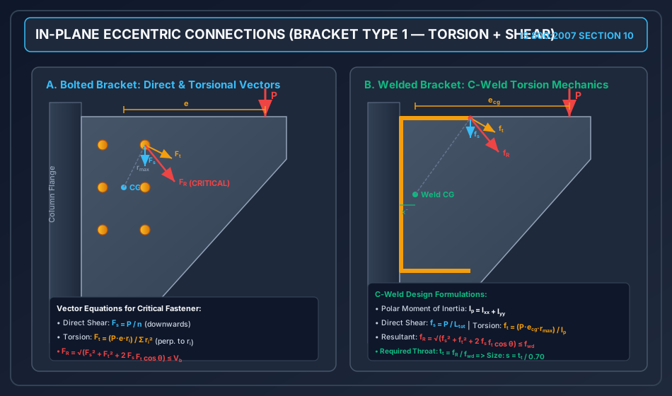
Key Architectural Insights from Figure 1:
- Kinematic Decoupling: The eccentric load acting at distance from the group centroid (CG) is resolved into an axial force acting at the CG and a planar twisting couple .
- Direct Shear Uniformity: Direct shear vectors point uniformly downward on every bolt in the assembly.
- Polar Variation of Torsional Shear: Torsional shear vectors act tangentially () with magnitude proportional to radial distance .
- Governing Critical Fastener: The top-right corner bolt experiences the smallest angle between and , resulting in the maximum resultant vector .
Figure 2: Bracket Type 2 (Out-of-Plane Bending & Neutral Axis Mechanics)
+----------------------------------------------------------------------------------------------------+
|                                BRACKET CONNECTION TYPE 2: OUT-OF-PLANE BENDING                     |
|                                                                                                    |
|       Column Face                  Tension Region (Bolts pull out)                                 |
|         | |     T1 <--- [Bolt Row 4] (Max Tension T_b)                                             |
|         | |     T2 <--- [Bolt Row 3]                                                               |
|         | |                                                                                        |
|    =====+=+================================== Neutral Axis (h/7 from bottom or CG)                  |
|         | |                                                                                        |
|         | |     C  ---> [Bearing Zone] (Flange compression contact)                                |
|         | |                                                                                        |
|         | |     V_sb = P_u / n (Vertical interface shear on all bolts)                             |
|         +------------------------------------------------------------------------------------------+
|         Interaction Criterion: (V_sb / V_dsb)^2 + (T_b / T_db)^2 <= 1.0 (Bearing Bolts)            |
+----------------------------------------------------------------------------------------------------+
The structural behavior of out-of-plane bracket connections (Bracket Type 2) is shown below:
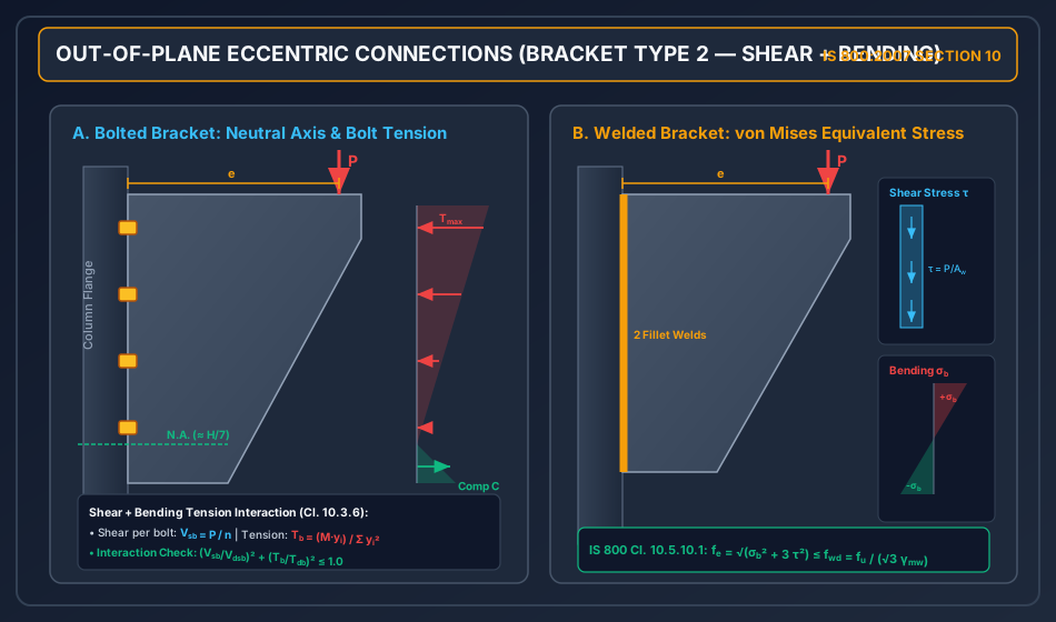
Key Architectural Insights from Figure 2:
- Dual Stress State: Fasteners are simultaneously subjected to vertical interface shear and longitudinal axial tension arising from out-of-plane flexure .
- Neutral Axis Location: Under elastic behavior, compression bearing develops against the column face near the bottom edge. Standard IS 800 formulations place the neutral axis at from the base.
- Extreme Tension Row: Fasteners in the top row () develop maximum tensile stress and dictate the design safety check.
- Elliptical Interaction Envelope: For bearing bolts, shear reduces tensile yield and vice-versa, governed strictly by the elliptical interaction curve of IS 800:2007 Cl. 10.3.6.
7. Step-by-Step Design Procedures & Workflows
7.1 Workflow: Design of In-Plane Bolted Bracket (Bracket Type 1)
[START: Given Factored Load P_u, Eccentricity e, Column Section]
       |
       v
[Step 1: Select Bolt Diameter & Grade]
       --> Choose M16, M20, or M24 (Grade 4.6 or 8.8 HSFG).
       --> Compute Bolt Value V_b = min(V_dsb, V_dpb).
       |
       v
[Step 2: Estimate Number of Bolts Required (n)]
       --> Approximate initial requirement: n_approx = sqrt((6 * P_u * e) / (V_b * p))
       --> Select standard 2-column or 3-column rectangular bolt layout.
       |
       v
[Step 3: Establish Group Geometry & Centroid]
       --> Set pitch p >= 2.5d, gauge g >= 2.5d, edge e' >= 1.5d_0.
       --> Calculate centroid (x_bar, y_bar) and eccentricity from CG e_cg.
       --> Calculate sum(r_i^2) = sum(x_i^2 + y_i^2).
       |
       v
[Step 4: Identify Critical Fastener]
       --> Find bolt with maximum r_i and acute angle theta between F_s and F_t.
       |
       v
[Step 5: Compute Resultant Force F_R]
       --> F_s = P_u / n (downwards)
       --> F_t = (P_u * e_cg * r_max) / sum(r_i^2) (perpendicular to r_max)
       --> F_R = sqrt(F_s^2 + F_t^2 + 2 * F_s * F_t * cos(theta))
       |
       v
[Step 6: Verification & Sufficiency Check]
       --> Is F_R <= V_b?
           |-- NO  --> Increase bolt size, pitch, or add bolts; repeat Step 3.
           |-- YES --> Check bracket plate thickness for bearing and block shear. [SAFE - END]
7.2 Workflow: Design of Out-of-Plane Bolted Bracket (Bracket Type 2)
- Calculate Design Actions: Direct shear , out-of-plane moment .
- Determine Fastener Demands:
- Shear per bolt: .
- Position Neutral Axis at from bottom of bracket plate.
- For all bolts located above NA (), calculate tensile force:
- Calculate Capacities per IS 800:2007:
- Shear capacity: .
- Tension capacity: .
- Perform Code Interaction Check:
- Check Plate Flexibility & Prying Action: Ensure bracket flange thickness satisfies prying criteria (refer to STEEL-01-04).
8. Solved Numerical Examples (Pre-Calculated & Multi-Step)
Problem 1: In-Plane Bolted Bracket Connection (Bracket Type 1)
Statement: A bracket plate is connected to the flange of an ISHB 300 column using 6 bolts of Grade 4.6 () and diameter (, ). The bolts are arranged in two vertical rows of 3 bolts each, with vertical pitch and horizontal gauge distance . The bracket carries a factored downward vertical load at an eccentricity from the centroid of the bolt group. The connecting plate thickness is (Fe 410, ). Determine whether the bolt group is safe against limit state failure.
       Load P_u = 65 kN
            |
            v
  +---------+
  |  Bracket Plate (t = 10 mm)
  |   (Col 1)    (Col 2)
  |     o          o     Row 3 (y = +70 mm)
  |        [CG]          Row 2 (y = 0 mm)
  |     o    x     o
  |     o          o     Row 1 (y = -70 mm)
  |   x = -40    x = +40
  +-----------------------+
Step 1: Group Geometry and Polar Moment () Centroid of bolt group lies at the geometric center:
- Coordinates of 6 bolts relative to CG in mm:
- Bolt 1 (Top Left):
- Bolt 2 (Top Right):
- Bolt 3 (Middle Left):
- Bolt 4 (Middle Right):
- Bolt 5 (Bottom Left):
- Bolt 6 (Bottom Right):
- Radial distance for 4 corner bolts:
- Radial distance for 2 middle bolts:
- Polar moment of the bolt group:
Step 2: Direct Shear Force ()
Step 3: Torsional Shear Force () Twisting moment:
For the extreme corner bolts ():
Step 4: Vector Resolution on Critical Fastener The critical fastener is Bolt 2 (Top Right at ). A clockwise moment generates a shear vector perpendicular to :
- Horizontal component:
- Vertical component:
- Net horizontal force:
- Net vertical force:
- Resultant shear force on critical bolt:
Step 5: Bolt Capacity () per IS 800:2007
- Design Shear Strength in single shear ():
- Design Bearing Strength on plate:
Step 6: Compliance Check
Conclusion: The connection is SAFE.
Problem 2: In-Plane Welded Bracket Connection (C-Shaped Fillet Weld)
Statement: A bracket plate is connected to a column flange using a C-shaped fillet weld. The weld runs along the top horizontal edge (), the vertical edge (), and the bottom horizontal edge (). The bracket carries a factored load at a distance from the vertical weld line. Steel grade is Fe 410 (), and welding is done in shop (). Calculate the required effective throat thickness and specify the minimum size of the fillet weld.
       b = 100 mm
    +--------------+
    | (x_bar, y_bar)
    |       o      |
dw  |              |-------------------------> P_u = 150 kN
    |              |       e = 200 mm
    |              |
    +--------------+
       b = 100 mm
Step 1: Total Weld Length and Centroid Location Let origin be at the bottom-left corner of the vertical weld line:
- Total perimeter:
- Centroidal coordinate :
- By symmetry:
- Net eccentricity from weld CG:
- Factored twisting moment:
Step 2: Polar Moment of Area of Weld Lines ( per unit throat)
- Second moment of area about -axis ():
- Two horizontal welds:
- Vertical weld:
- Second moment of area about -axis ():
- Vertical weld at :
- Two horizontal welds:
- Polar Moment:
Step 3: Critical Stress Point on Weld The critical point is the far corner :
- Coordinates from CG:
- Radius:
Step 4: Shear Stresses per Unit Throat Thickness
- Direct Shear:
- Torsional Shear:
- Components of :
- Combined force components:
- Resultant force per mm length:
Step 5: Throat Thickness & Weld Size Design shear strength of weld per IS 800:2007 Cl. 10.5.7.1:
Required throat thickness:
Required weld size for fillet weld ():
Problem 3: Out-of-Plane Bolted Bracket Connection (Bracket Type 2)
Statement: A bracket plate is connected to a column flange carrying a factored vertical load at an eccentricity acting perpendicular to the connection face. The joint utilizes 8 bolts of Grade 4.6, (), arranged in two vertical rows of 4 bolts each. The vertical pitch is . The bolt capacities are and . Check the safety of the connection using the IS 800:2007 interaction formula.
       Load P_u = 100 kN
            |
            v  e = 180 mm
    +-------+
    | (Col 1)  (Col 2)
    |   o        o      Row 4: y = +120 mm
    |   o        o      Row 3: y = +40 mm
    | ===== [CG] =====  y = 0 mm
    |   o        o      Row 2: y = -40 mm
    |   o        o      Row 1: y = -120 mm
    +-------------------+
Step 1: Factored Design Actions
- Factored shear force:
- Factored out-of-plane moment:
Step 2: Applied Shear Force per Bolt ()
Step 3: Applied Tensile Force on Extreme Bolt () Assuming rotation about the centroid of the bolt group:
- Vertical positions relative to CG for each pair of bolts:
- Row 4:
- Row 3:
- Row 2:
- Row 1:
- Sum of squares:
- Tensile force in the extreme top bolts (Row 4):
Step 4: Interaction Criterion per IS 800:2007 Cl. 10.3.6 For bearing bolts subjected to combined shear and tension:
Substituting the calculated values:
Since , the connection is SAFE with substantial structural reserve (30.5% utilization).
9. Common Pitfalls, Edge Cases & Failure Modes
- Failure to Measure Eccentricity from Group Centroid ():
- Pitfall: Using the distance from the column face rather than from the CG of the bolt or weld group.
- Consequence: Underestimating or overestimating the twisting moment . For asymmetric C-welds, significantly shifts the neutral pole.
- Incorrect Vector Angle in Critical Bolt Identification:
- Pitfall: Assuming the top-outermost bolt is always critical without verifying the direction of .
- Reality: For a clockwise torque, the top-right bolt has an acute angle (), producing maximum resultant . The top-left bolt has an obtuse angle (), resulting in a smaller vector sum.
- Linear vs. Elliptical Interaction Confusion:
- Pitfall: Applying the linear interaction formula to standard bearing bolts.
- Correction: Bearing bolts follow the elliptical interaction . The linear interaction is strictly reserved for HSFG friction grip bolts (where external tension directly relieves the clamping pre-load ).
- Ignoring Column Web Buckling/Crippling:
- Pitfall: Designing a robust bracket connection while failing to verify the column web behind the bracket for local compression buckling or flange distortion.
10. Exam-Specific Focus Points & Rapid Revision Notes
10.1 Quick Revision Formula Card
- Centroid: ,
- Polar Moment of Inertia:
- Direct Shear:
- Torsional Shear:
- Resultant Shear:
- Critical Bolt Criteria: , (acute angle between and ).
- Fillet Weld Polar Modulus: ; .
- Bearing Bolt Interaction: .
- HSFG Bolt Interaction: .
10.2 Examination Nuances
- GATE CE: Questions often test rapid vector resolution: "Calculate the resultant force on bolt A vs bolt B", where one requires addition of components and another requires subtraction.
- ESE Prelims: Frequently asks for the number of bolts needed using the semi-empirical formula .
- SSC JE & State AE/JE: Direct factual questions on interaction formulas (linear for HSFG vs elliptical for bearing bolts) and location of the neutral axis ( from bottom).
11. Practice Problems & Self-Assessment Question Bank
- Question 1 (Conceptual): In an in-plane eccentric bolted bracket connection, why is the critical fastener located at the maximum radial distance with the minimum angle between direct and torsional shear vectors?
- Answer: Because resultant shear . Maximum maximizes , and an acute angle () yields positive , maximizing the additive interaction term .
- Question 2 (Formula Application): An M20 Class 4.6 bolt in an out-of-plane bracket connection is subjected to factored shear and factored tension . If and , determine the interaction index.
- Answer: (Safe).
- Question 3 (GATE Numeric): A bracket connection has 4 bolts located at from CG. A downward load acts at clockwise from CG. Compute the direct shear , torsional shear , and resultant on the top-right bolt.
- Answer: . . . . . , (downwards). Total , . .
- Question 4 (Welded Bracket): For a bracket welded with two vertical lines of weld of length separated by distance , express the polar moment of area per unit throat thickness about the centroid.
- Answer: Centroid is at midpoint (). . . .
- Question 5 (HSFG vs Bearing Interaction): Explain why HSFG bolts follow a linear interaction relation whereas bearing bolts follow an elliptical interaction relation under combined shear and tension.
- Answer: In HSFG joints, external tension directly counteracts the initial clamping pre-stress (), linearly reducing the available frictional clamping force without needing material yielding. In bearing bolts, failure occurs by material yield/fracture of the bolt steel under combined bi-axial stress, which follows the von Mises / Tresca elliptical yield envelope.
12. Bibliographic References & Standard Codes
- Bureau of Indian Standards: IS 800:2007 — General Construction in Steel — Code of Practice (Third Revision), BIS, New Delhi.
- Subramanian, N.: Design of Steel Structures (Limit State Method), Oxford University Press, 2018.
- Duggal, S. K.: Limit State Design of Steel Structures, McGraw Hill Education (India), 2nd Edition, 2019.
- Bhavikatti, S. S.: Design of Steel Structures By Limit State Method as per IS: 800-2007, I.K. International Publishing House.
- Teaching Resource for Structural Steel Design (INSDAG): Institute for Steel Development & Growth, Volume 2: Connections, Kolkata.