Plate Girder Fundamentals, Proportioning & Flange Design
In this chapter (4 topics)
On this page
- 1. Topic Overview & Engineering Significance
- 2. Code Provisions & Theoretical Derivations
- 2.1 Derivation of Economical Depth & Weight Equality Theorem
- 2.2 Web Slenderness Limits (IS 800:2007 Cl. 8.6.1)
- 2.3 Flange Design & Cross-Section Classification (IS 800 Cl. 8.6.1.2 & Table 2)
- 2.4 Flange Curtailment Mechanics (IS 800:2007 Cl. 8.6.3)
- 3. Visual Diagrams & Structural Behavior
- Figure 1: Welded Plate Girder Anatomy & Web Slenderness Limits
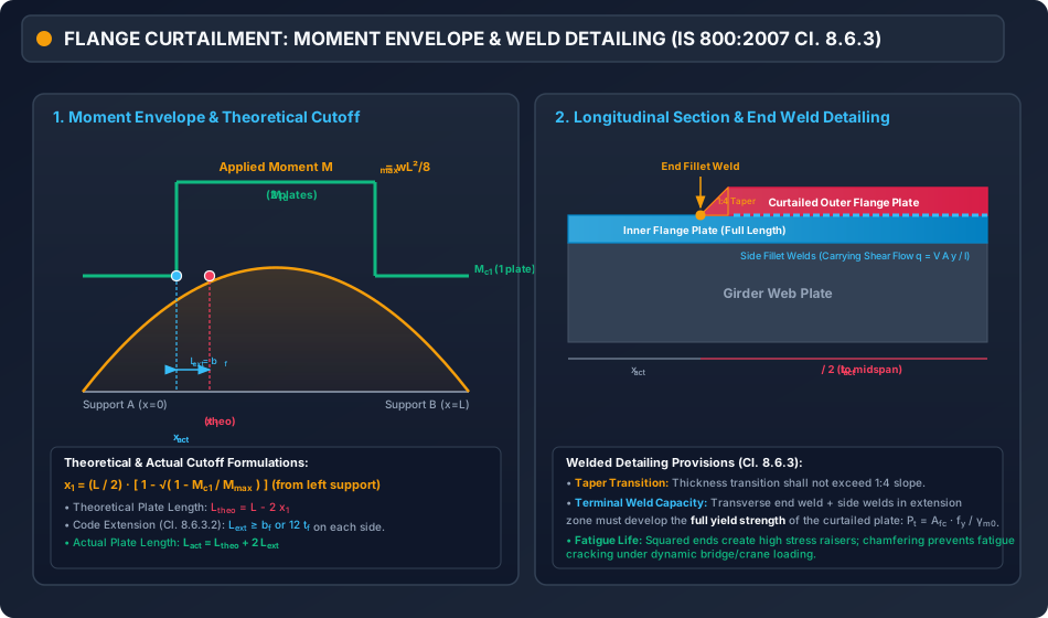
- Figure 2: Flange Curtailment Envelope & Welded Joint Detailing
- 4. Mathematical Formulations & Design Procedures
- 5. Solved Numerical Examples
- Problem 1: Complete Optimum Proportioning of a Welded Plate Girder
- Problem 2: Flange Curtailment Analysis
- Problem 3: Slenderness Regimes & Stiffener Provision Hierarchy
- 6. Comparative Engineering Analysis
- 7. Design Pitfalls & Practical Field Considerations
- 8. Summary of Critical Formulae
- 9. Exam Traps & Tricks
- 10. Recommended Indian Standard Codes & Textbooks
- 11. Practice Problems with Answer Keys
- Problem 1 (GATE CE Objective)
- Problem 2 (UPSC ESE Objective)
- Problem 3 (GATE CE Numerical Answer Type)
- 12. Cross-Topic Linkages & Forward References
1. Topic Overview & Engineering Significance
When structural steel spans exceed or when applied bending moments and shear forces surpass the capacity of standard hot-rolled I-sections (such as ISMB 600 or ISHB 450), engineers turn to built-up flexural members known as Plate Girders. A plate girder is fabricated by welding two flange plates to a central web plate, producing deep, customized cross-sections optimized for heavy railway bridges, highway flyovers, industrial transfer girders, and overhead travelling crane runways.
Under IS 800:2007 Cl. 8.6, the design of a welded plate girder differs fundamentally from that of a standard rolled beam:
- Geometric Separation of Functions: The deep, thin web plate ( typically ) is proportioned primarily to resist transverse shear forces (), while the wide, thick flange plates are proportioned to resist the bending moment () as an internal axial force couple ().
- Optimum Economical Proportioning: The total steel volume is minimized by selecting an optimum depth , where . At this optimum depth, a fundamental structural theorem dictates that the weight of the web plate equals the total weight of both flanges ().
- Web Slenderness Hierarchy: Because the web is thin, out-of-plane serviceability buckling and shear buckling are strictly controlled through a code-mandated hierarchy of slenderness limits (), dictating whether the web can remain unstiffened or requires transverse and longitudinal stiffeners.
- Flange Curtailment: Because bending moments peak at midspan and diminish towards supports, outer flange plates are terminated (curtailed) along the span to save substantial material.
Mastery of plate girder proportioning, web slenderness regimes, and flange curtailment mechanics is essential for large-scale infrastructure design and is among the most heavily tested topics in UPSC ESE, GATE CE, and State AE/JE examinations.
2. Code Provisions & Theoretical Derivations
2.1 Derivation of Economical Depth & Weight Equality Theorem
Consider a simply supported welded plate girder subjected to a maximum factored bending moment . Let:
- = clear web depth
- = web thickness
- = web slenderness ratio (aspect ratio)
- = area of one flange plate
- = design yield stress
Assuming conservatively that the flanges resist the entire bending moment as an axial couple with lever arm approximately equal to :
The total cross-sectional steel area of the girder (ignoring welds and stiffeners) is:
To find the depth that minimizes the total material consumption, differentiate with respect to and set :
Corresponding optimum web thickness:
The Golden Weight Equality Theorem:
Substitute into the web area and the combined flange area :
(Notice: If moment of resistance includes the web's contribution , exact derivation gives . Therefore, in an economically proportioned plate girder, the weight of the web plate is equal to the total weight of both flanges!)
2.2 Web Slenderness Limits (IS 800:2007 Cl. 8.6.1)
To prevent serviceability web wrinkling under self-weight, out-of-plane distortion during fabrication, and premature elastic shear buckling:
| Structural Configuration | Code Requirement / Limiting Web Slenderness () | Governing Mechanics |
|---|---|---|
| No Intermediate Transverse Stiffeners | Maximum limit for unstiffened web serviceability. | |
| Intermediate Transverse Stiffeners () | Vertical stiffeners spaced widely (). | |
| Intermediate Transverse Stiffeners () | Vertical stiffeners spaced closely (). | |
| Transverse Stiffeners + 1 Longitudinal Stiffener at | Horizontal stiffener at prevents bending compressive buckling. | |
| Transverse + 2 Longitudinal Stiffeners ( and ) | Second stiffener at neutral axis prevents shear + axial buckling. | |
| Absolute Code Upper Bound | Under no circumstances shall exceed ! |
2.3 Flange Design & Cross-Section Classification (IS 800 Cl. 8.6.1.2 & Table 2)
1. Flange Outstand Ratio ():
For a welded I-girder, the outstand is the projection from the web face to the flange edge:
From IS 800:2007 Table 2 (Limiting Width-to-Thickness Ratios):
- Class 1 (Plastic):
- Class 2 (Compact):
- Class 3 (Semi-Compact):
2. Design Moment Resistance ():
For Class 1 and Class 2 sections under low shear ():
Where , and the plastic modulus of the built-up section is:
(Notice that the web contributes , which typically provides of the total plastic bending resistance!)
2.4 Flange Curtailment Mechanics (IS 800:2007 Cl. 8.6.3)
In simply supported plate girders subjected to uniformly distributed loads, the bending moment follows a parabola:
At sections away from midspan, the bending moment decreases rapidly. Flange plates are fabricated with multiple plates (e.g., one continuous base plate plus one or more outer cover plates). Outer plates are terminated where the remaining section can safely resist the applied moment.
1. Theoretical Cutoff Point ():
Equating the moment capacity of the curtailed section to the applied moment :
The theoretical length of the curtailed plate is:
2. Actual Cutoff Point & Code Extension (IS 800 Cl. 8.6.3.2):
A curtailed flange plate cannot be abruptly terminated at the theoretical cutoff point because the plate carries a large axial force that must be developed and transferred back into the girder through weld shear. IS 800:2007 requires that the curtailed plate extend beyond the theoretical cutoff point by an extension length :
Where is the flange width and is the thickness of the curtailed plate.
The actual length of the curtailed plate is:
And the actual cutoff distance from the support is:
3. Weld Connection Detailing (Cl. 8.6.3.3):
- Terminal End Fillet Weld: Provided across the full width at each end of the curtailed plate.
- Side Fillet Welds: Continuous longitudinal welds designed to transmit the horizontal shear flow : Where is the area of the curtailed plate, and is the distance from the neutral axis to the centroid of the curtailed plate.
3. Visual Diagrams & Structural Behavior
Figure 1: Welded Plate Girder Anatomy & Web Slenderness Limits
The diagram below illustrates the cross-sectional anatomy, golden proportioning parameters, and the statutory web slenderness spectrum hierarchy.
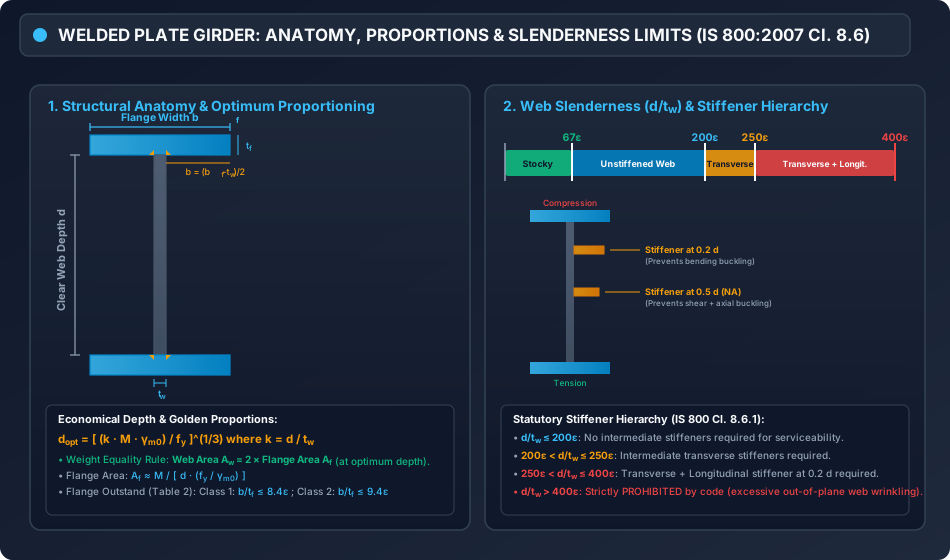
Figure 2: Flange Curtailment Envelope & Welded Joint Detailing
The figure below depicts the parabolic moment diagram, the stepped moment capacity envelope, theoretical vs actual cutoff locations, and the 1:4 taper weld detail.
4. Mathematical Formulations & Design Procedures
+---------------------------------------------------------------------------------+
|            FLOWCHART: WELDED PLATE GIRDER PROPORTIONING ALGORITHM               |
+---------------------------------------------------------------------------------+
                                         |
                                         v
                         [ Step 1: Input Factored Actions ]
                         Design Moment: Mu ; Design Shear: Vu ; Span: L
                         Material: fy, gm0 = 1.10, E = 2e5 MPa
                                         |
                                         v
                     [ Step 2: Select Web Aspect Ratio k = d/tw ]
                     Unstiffened web:              k = 150 to 180 (<= 200)
                     Transverse stiffened web:     k = 180 to 220 (<= 250)
                     Longitudinal stiffened web:   k = 250 to 350 (<= 400)
                                         |
                                         v
                    [ Step 3: Compute Economical Depth d_opt ]
                           d_opt = [ (k * Mu * gm0) / fy ]^(1/3)
                           tw_opt = d_opt / k
                           Round off d and tw to standard plate sizes
                                         |
                                         v
                         [ Step 4: Verify Web Slenderness ]
                         Check d / tw <= 200 epsilon (if unstiffened)
                         Check d / tw <= 250 epsilon (transverse stiffeners)
                         Check d / tw <= 400 epsilon (transverse + longitudinal)
                                         |
                                         v
                         [ Step 5: Design Flange Plates ]
                         Af_req ≈ Mu / [ d * (fy / gm0) ]
                         Select bf and tf such that:
                         - bf ≈ 0.25 d to 0.35 d
                         - Outstand b = (bf - tw) / 2
                         - Check b / tf <= 8.4 epsilon (Class 1) or 9.4 epsilon (Class 2)
                                         |
                                         v
                     [ Step 6: Verify Moment & Shear Capacities ]
                     Zp = bf * tf * (d + tf) + (tw * d^2) / 4
                     Md = Zp * fy / gm0 >= Mu
                     Vd = (d * tw * fy) / [ sqrt(3) * gm0 ] >= Vu
                     Check if V <= 0.60 Vd (Low Shear)
                                         |
                                         v
                       [ Step 7: Flange Curtailment (if multi-plate) ]
                       Compute Mc1 for single plate section
                       Theoretical cutoff: x1 = (L/2) [ 1 - sqrt(1 - Mc1/Mmax) ]
                       Extension: Lext = max(bf, 12 tf)
                       Actual cutoff: x_act = x1 - Lext
                       Design terminal end and side fillet welds
5. Solved Numerical Examples
Problem 1: Complete Optimum Proportioning of a Welded Plate Girder
Statement:
A welded plate girder is to be designed for a factory building to support a maximum factored bending moment and a factored shear force . Steel grade is E250 (, , ).
- Determine the optimum economical depth and web thickness assuming a web aspect ratio .
- Adopt practical plate dimensions and verify web slenderness.
- Design the flange plates satisfying Class 2 (Compact) outstand limits.
- Calculate the plastic moment capacity and design shear resistance of the final section.
Solution:
Step 1: Economical Web Depth () Design yield strength:
Using the economical depth formula with :
Theoretical optimum web thickness:
Step 2: Practical Adoption & Web Slenderness Check
- Adopt clear web depth:
- Adopt standard web plate thickness:
- Actual web aspect ratio:
- Slenderness limit check (IS 800 Cl. 8.6.1): The web satisfies the serviceability slenderness limit without requiring intermediate transverse stiffeners!
Step 3: Flange Design
-
Approximate required flange area:
-
Select flange width : Typically .
Adopt . -
Outstand of flange from web face:
-
Flange thickness to satisfy Class 2 (Compact) limit (Table 2):
Adopt flange plate thickness: .
-
Provided flange area:
(Notice that is slightly less than the crude estimate because the web plate has and carries substantial bending moment! Let us verify the exact plastic moment capacity).
Step 4: Plastic Section Modulus & Moment Capacity () Center-to-center distance between flanges:
Plastic modulus of the cross-section:
Design bending strength :
Verification:
Step 5: Design Web Shear Capacity () For a welded I-girder, the effective shear area is :
Low shear limit:
Verification:
Problem 2: Flange Curtailment Analysis
Statement:
A simply supported welded plate girder of span carries a total factored uniformly distributed load (inclusive of self-weight).
The girder cross-section at midspan consists of:
- Web: ().
- Flanges: Two plates of on each flange (total flange thickness ).
Steel grade is E250 ().
The outer flange plate of is to be curtailed when no longer required, leaving one continuous inner plate of .
Determine:
- The moment capacity of the midspan section and the curtailed section.
- The theoretical cutoff distance from the support.
- The actual length of the curtailed plate in accordance with IS 800:2007.
Solution:
Step 1: Applied Maximum Moment
Step 2: Moment Capacity of Midspan & Curtailed Sections Design yield stress: . Web plastic modulus:
-
Midspan Section (2 plates: ):
-
Curtailed Section (1 plate: ):
Step 3: Theoretical Cutoff Distance () Equating applied moment to :
The theoretical cutoff point is located at from each support. Theoretical length of the outer curtailed plate:
Step 4: Code Extension & Actual Length () From IS 800:2007 Cl. 8.6.3.2, the curtailed plate must extend beyond the theoretical cutoff point by:
Actual length of curtailed plate:
The actual cutoff point from the support:
Conclusion:
The outer cover plate has an actual total length of , centered symmetrically at midspan (extending from to from the left support).
Problem 3: Slenderness Regimes & Stiffener Provision Hierarchy
Statement:
A plate girder web has a clear depth and is fabricated from Fe 410 steel ().
Categorize the web slenderness and state the mandatory stiffener requirements for:
Solution:
-
Case 1 ():
Since :
Classification: Shear buckling occurs, but the web satisfies the serviceability limit without intermediate stiffeners. Transverse stiffeners are optional for serviceability, but are required if Tension Field Action (TFA) is to be mobilized. -
Case 2 ():
Since :
Classification: Intermediate Transverse Stiffeners are MANDATORY (spaced at ) to prevent out-of-plane serviceability web buckling. No longitudinal stiffener is required. -
Case 3 ():
Since :
Classification: Highly slender web!
Mandatory Stiffeners:- Intermediate Transverse Stiffeners.
- One Longitudinal Stiffener at from the compression flange (to prevent bending compressive buckling).
(If exceeded , it would be strictly prohibited by IS 800:2007 Cl. 8.6.1).
6. Comparative Engineering Analysis
| Attribute | Hot-Rolled I-Beam (e.g. ISMB 600) | Welded Plate Girder |
|---|---|---|
| Span Range | Economical up to | Economical for |
| Cross-Section Depth | Standardized, fixed () | Tailored, arbitrary depth () |
| Web Slenderness () | Low to moderate () | Very high () |
| Shear Failure Mode | Plastic shear yielding () | Elastic/inelastic shear buckling ( or TFA) |
| Stiffener Requirements | None (except at heavy point loads) | Systematic network of transverse & longitudinal stiffeners |
| Material Distribution | Fixed flange/web proportion | Optimized: with curtailed flanges |
7. Design Pitfalls & Practical Field Considerations
-
Abrupt Curtailment without Extension Length ():
Fabricators occasionally terminate cover plates at the exact theoretical cutoff point. At this point, the outer plate is carrying massive tension/compression forces. Without extending by and detailing the end fillet weld, the cover plate peels away from the inner plate, causing catastrophic joint failure. -
Neglecting the Web's Contribution to Plastic Moment Capacity:
While approximate hand calculations assume , computerized or exact limit state design per IS 800 must include . Neglecting the web can underestimate the section's plastic capacity by , leading to oversized flanges. -
Exceeding the Absolute Slenderness Ceiling:
Some designers attempt to save steel by reducing web thickness in very deep girders () beyond . Even with multiple longitudinal stiffeners, IS 800:2007 strictly prohibits due to dynamic vibration and excessive out-of-plane web "oil-canning". -
Fatigue at Cover Plate Terminations:
In railway and crane bridge girders subjected to cyclic fatigue, squared cutoffs create severe notch stress concentrations. Flange cover plates must be provided with a chamfered / tapered end to ensure smooth stress flow and prevent fatigue crack initiation.
8. Summary of Critical Formulae
========================================================================================
                      PLATE GIRDER DESIGN FORMULAE CHEAT SHEET
========================================================================================
• Optimum Economical Depth:
    d_opt = [ (k * Mu * gm0) / fy ]^(1/3)    (where k = d / tw)
    t_w_opt = d_opt / k

• Golden Rule of Economical Plate Girders:
    Aw = 2 Af    (Weight of web = Weight of both flanges)

• Flange Outstand Limits (Welded Sections, Table 2):
    Class 1 (Plastic):     b / tf <= 8.4 epsilon
    Class 2 (Compact):     b / tf <= 9.4 epsilon
    Class 3 (Semi-Compact): b / tf <= 13.6 epsilon
    (where b = (bf - tw) / 2)

• Web Slenderness Hierarchy (Cl. 8.6.1):
    d / tw <= 67 epsilon   --> Stocky Web (Full plastic shear, no buckling)
    d / tw <= 200 epsilon  --> Unstiffened Web (Serviceability limit)
    d / tw <= 250 epsilon  --> Transverse Stiffeners Mandatory (c <= 1.5 d)
    d / tw <= 400 epsilon  --> Transverse + Longitudinal Stiffener at 0.2 d Mandatory
    d / tw > 400 epsilon   --> STRICTLY PROHIBITED

• Flange Curtailment (Under Factored UDL):
    Theoretical Cutoff:    x1 = (L / 2) [ 1 - sqrt(1 - Mc1 / Mmax) ]
    Code Extension:        Lext >= max(bf, 12 tf)
    Actual Cutoff:         x_act = x1 - Lext
========================================================================================
9. Exam Traps & Tricks
-
The Weight Equality Question:
Question: "In an economically designed plate girder, the weight of the web plate is equal to:"
Options: (A) Weight of one flange (B) Weight of both flanges (C) Half the weight of one flange (D) Twice the weight of both flanges
Answer: (B) Weight of both flanges (). -
The Maximum Permissible Slenderness:
Question: "What is the absolute maximum limit of for a plate girder web with transverse and longitudinal stiffeners?"
Answer: (for E250 steel, ). -
The Longitudinal Stiffener Level:
Question: "The first longitudinal stiffener in a plate girder is provided at what distance from the compression flange?"
Answer: (or ). If a second longitudinal stiffener is provided, it is at the neutral axis (). -
Extension Length Trap:
In competitive exam MCQs, the extension length beyond the theoretical cutoff point is or (whichever is greater), NOT span/10 and NOT !
10. Recommended Indian Standard Codes & Textbooks
- IS 800:2007: General Construction in Steel — Code of Practice, Bureau of Indian Standards, New Delhi. (Sections 8.6, 8.7, and Table 2).
- Subramanian, N.: Design of Steel Structures (Limit State Method), Oxford University Press.
- Duggal, S.K.: Limit State Design of Steel Structures, McGraw Hill Education.
- Bhavikatti, S.S.: Design of Steel Structures (IS: 800-2007), I.K. International Publishing House.
11. Practice Problems with Answer Keys
Problem 1 (GATE CE Objective)
In a welded plate girder, if the maximum factored bending moment is , web aspect ratio is , and design yield stress is , the economical depth of the web is proportional to:
(A)
(B)
(C)
(D)
Answer: (B)
Hint: From optimization derivation, .
Problem 2 (UPSC ESE Objective)
As per IS 800:2007, an unstiffened web plate in a plate girder can have a maximum clear depth to thickness ratio () of:
(A)
(B)
(C)
(D)
Answer: (C)
Hint: Cl. 8.6.1 specifies as the maximum serviceability limit without intermediate transverse stiffeners. (Note: is the threshold for shear buckling, but unstiffened webs are permitted up to using post-critical shear resistance).
Problem 3 (GATE CE Numerical Answer Type)
A plate girder flange consists of an inner continuous plate and an outer curtailed plate of width and thickness . The theoretical cutoff point is located at from the support. The minimum distance from the support at which the curtailed plate can actually be terminated (in , rounded to two decimal places) is ______.
Answer: 6.10
Hint: .
.
12. Cross-Topic Linkages & Forward References
- Preceding Chapter: Chapter 04: Design of Beams and Flexural Members — Rolled beam theory, high shear interaction, and LTB.
- Inaugural Chapter Milestone: Initiates Chapter 05: Design of Plate Girders & Industrial Trusses!
- Following Topic: Topic 02: Post-Buckling Shear Mechanics & Tension Field Action (STEEL-05-02) — Diagonal tension fields in thin web panels, Basler & Rockey models, and post-buckling shear strength .