Lug Angles, Tension Member Splices & Slenderness Limits (IS 800:2007 Cl. 10.8, Cl. 10.2.4 & Table 3)
In this chapter (4 topics)
On this page
- 1. Engineering Context & Overview
- 2. Structural Mechanics & Working Principles of Lug Angles
- 2.1 The Physics of Lug Angle Action
- 3. Governing Indian Standard Code Provisions for Lug Angles (IS 800:2007 Cl. 10.8)
- 3.1 Lug Angles for Single Angle Members (IS 800:2007 Cl. 10.8.1)
- 3.2 Lug Angles for Channel Members (IS 800:2007 Cl. 10.8.2)
- 3.3 Mandatory Detailing Rules (IS 800:2007 Cl. 10.8.3 - Cl. 10.8.5)
- 4. Tension Member Splices & Packing Plates
- 4.1 Splice Topologies: Lap Splice vs Double Cover Butt Splice
- 4.2 Packing Plates & Reduction Factor βpk (IS 800:2007 Cl. 10.2.4)
- 5. Slenderness Limits for Tension Members (IS 800:2007 Table 3)
- 5.1 Why Limit Slenderness in Tension Members?
- 5.2 Comprehensive Table 3 Matrix (IS 800:2007)
- 5.3 Tack Bolting Requirements for Double Angles (IS 800:2007 Cl. 10.2.5.5)
- 6. International Standards Comparison
- 7. Architectural SVG Technical Illustrations
- 7.1 Lug Angle Connection Mechanics and Detailing
- 7.2 Tension Splices, Packing Plates and Slenderness Limits
- 8. Step-by-Step Pre-Calculated Numerical Problems
- Problem 1: Complete Design of Lug Angle Connection
- Problem 2: Tension Member Splice with Packing Plate
- Problem 3: Slenderness Ratio Evaluation across Service Loadings (Table 3)
- 9. Comprehensive Summary & Comparative Analysis Table
- 10. Critical Practical Design & Detailing Guidelines
- 11. Site Pitfalls, Fabrication Blunders & Inspection Failures
- 12. Competitive Examination Traps & Multiple-Choice Practice Questions
- Trap 1: Lug Angle Fastener Multipliers
- Trap 2: Packing Plate Reduction Threshold
- Trap 3: Table 3 Slenderness Category Distinctions
- Practice Question 1 (GATE CE)
- Practice Question 2 (UPSC ESE)
- Practice Question 3 (SSC JE / State AE)
1. Engineering Context & Overview
In structural engineering systems—such as industrial mill buildings, transmission towers, railway truss bridges, and long-span roof trusses—tension members are subjected to substantial axial forces. While simple flat plates or single angles with small loads can be connected directly to gusset plates through a single line of fasteners, heavy tensile loads introduce severe engineering challenges:
- Excessive Connection Length & Uneconomic Gusset Plates: When a large angle or channel section is connected through only one leg or the web, the entire load must be transferred through a single line of fasteners. If 10 to 14 bolts are required, the connection length () easily exceeds . This demands enormous, expensive gusset plates and introduces severe shear lag into the member.
- Member Length Restrictions & Cross-Section Transitions: Rolled steel angles, channels, and plates are manufactured in finite rolling mill lengths (typically to ). Long-span trusses ( to ) necessitate tension splices. Furthermore, chord members in large trusses often decrease in thickness towards the supports as tensile forces vary, requiring splices between plates of unequal thickness.
- Vibration, Sagging & Stress Reversal in Tension Members: Although tension members do not suffer from classical Euler flexural buckling under tension, long, slender ties easily sag under their own self-weight. In high winds or under machine vibration, slender members undergo violent lateral oscillation (whipping). Moreover, under dynamic wind uplift or crane surges, members designed as tension ties can experience transient stress reversal into compression.
To address these practical challenges, the Indian Standard Code of Practice for General Construction in Steel (IS 800:2007) provides explicit specifications:
- Clause 10.8 governs the design and detailing of Lug Angles to shorten end connections and eliminate shear lag penalties.
- Clause 10.2.4 governs Packing Plates in splices, providing strict bolt shear reduction factors () when filler plates exceed .
- Table 3 establishes rigorous Maximum Effective Slenderness Ratios () ranging from to depending on the presence and cause of stress reversal.
2. Structural Mechanics & Working Principles of Lug Angles
2.1 The Physics of Lug Angle Action
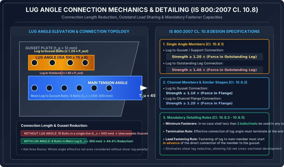
A lug angle is a short auxiliary piece of angle section attached to the outstanding leg of a main tension angle (or the flanges of a channel member) and connected directly to the gusset plate.
       ═══════════════════════════════════════════════════════════════════
                    GUSSET PLATE (t_g)
       ───────────────────────────────────────────────────────────────────
          o     o     o     o   <── Lug to Gusset Connection (≥ 1.20 P_out)
       ┌────────────────────────┐
       │       LUG ANGLE        │
       └────────────────────────┘
          *     *     *     *   <── Lug to Outstanding Leg (≥ 1.40 P_out)
       ═══════════════════════════════════════════════════════════════════
       ───────────────────────────────────────────────────> Force T_u
       [ MAIN CONNECTED LEG ]   o   o   o   o   o   o   (Direct to Gusset)
       ═══════════════════════════════════════════════════════════════════
By connecting both legs of the main angle to the gusset plate:
- Load Sharing Across Both Legs: The total tensile load is divided between the connected leg () and the outstanding leg (). The lug angle bypasses the outstanding leg force directly into the gusset.
- Dramatic Reduction in Connection Length (): Because only the connected leg load () is transferred directly through the main leg, the required number of fasteners on the main leg is reduced by . The connection length shrinks proportionally, allowing compact, economical gusset plates.
- Elimination of Shear Lag Penalty: With both legs effectively anchored to the gusset, the cross-section behaves uniformly. Under IS 800:2007, when lug angles conforming to Cl. 10.8 are provided, the entire net cross-sectional area () is mobilized without any shear lag reduction factor ().
- Reduction in Joint Eccentricity: Fastening both legs brings the center of resistance of the bolt group much closer to the center of gravity of the angle, drastically minimizing out-of-plane secondary bending moments.
3. Governing Indian Standard Code Provisions for Lug Angles (IS 800:2007 Cl. 10.8)
3.1 Lug Angles for Single Angle Members (IS 800:2007 Cl. 10.8.1)
When lug angles are used to connect an angle tension member:
- Lug to Gusset Connection: The lug angles and their connection to the gusset or other supporting member shall be capable of developing a strength not less than in excess of the force in the outstanding leg of the angle:
- Lug to Main Angle Connection: The attachment of the lug angle to the main angle shall be capable of developing a strength not less than in excess of that force:
Rationale for Excess Capacity Factors ( and ):
The load transfer from the outstanding leg into the lug angle, and subsequently from the lug angle into the gusset, is an indirect, eccentric load path. Stress concentrations and localized deformation gradients inevitably develop. The code mandates safety margins of and to guarantee that the auxiliary lug angle connection does not fail before the main member reaches its design plastic limit.
3.2 Lug Angles for Channel Members (IS 800:2007 Cl. 10.8.2)
In the case of channel sections and similar built-up shapes where the web is connected directly to the gusset plate:
- Lug to Gusset Connection: Shall develop a strength not less than in excess of the force in the flange:
- Lug to Flange Connection: Shall develop a strength not less than in excess of the force in the flange:
3.3 Mandatory Detailing Rules (IS 800:2007 Cl. 10.8.3 - Cl. 10.8.5)
- Minimum Fastener Mandate (Cl. 10.8.3): In no case shall less than 2 bolts, rivets, or welds be used for attaching the lug angle to the gusset or to the member. A single fastener is strictly prohibited because it permits rotation and creates localized stress singularities.
- Termination Rule (Cl. 10.8.4): The effective connection of the lug angle shall, as far as possible, terminate at the end of the member connected.
- Lead Fastening Rule (Cl. 10.8.5): The fastening of the lug angle to the main member shall preferably start in advance of the direct connection of the member to the gusset plate. This ensures early load pickup by the lug angle before the direct connection engages.
4. Tension Member Splices & Packing Plates
4.1 Splice Topologies: Lap Splice vs Double Cover Butt Splice
Tension members can be spliced using either a single lap joint or a double-cover butt joint:
  (A) Single Lap Splice (Eccentric):      (B) Double Cover Butt Splice (Symmetrical):
      P <═══■■■■■■■■■                         P <═══■■■■■  [Top Cover]  ■■■■■═══> P
            o  o  o  <-- Single Shear               o    o              o    o  <-- Double Shear
            ■■■■■■■■■═══> P                   P <═══■■■■■■■■■■ | ■■■■■■■■■■═══> P
      Result: Large Bending Moment M = P·e          o    o              o    o
      Severe prying & bolt bending!           P <═══■■■■■ [Bottom Cover] ■■■■■═══> P
                                              Result: Concentric, Zero Moment, Double Shear
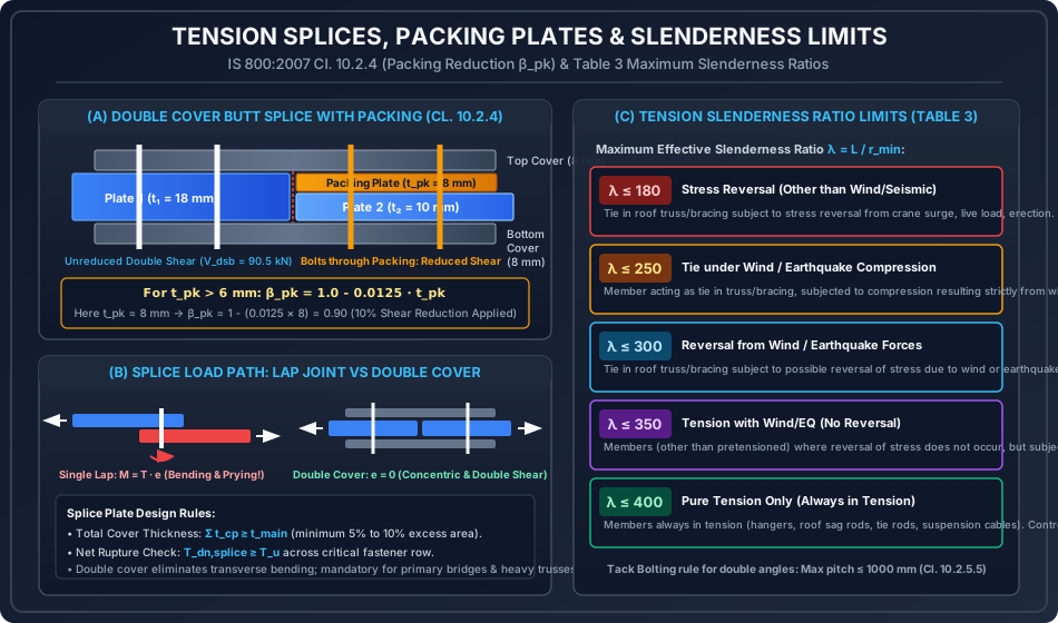
- Single Lap Splice: Highly undesirable in primary structural engineering. The line of action of the opposing forces has an eccentricity equal to the average plate thickness (). This eccentricity produces a severe secondary bending moment (), forcing the plates to bend out-of-plane and inducing severe prying tension on the fasteners.
- Double Cover Butt Splice: The industry standard for heavy structural applications. The main plates butt against each other along the centerline, and two symmetrical cover plates (one top, one bottom) sandwich the joint.
- Symmetrical load path: Zero eccentricity ().
- Fasteners operate in Double Shear, doubling their shear capacity ().
- Total thickness of cover plates must exceed the main member thickness: Typically, each cover plate has thickness .
4.2 Packing Plates & Reduction Factor (IS 800:2007 Cl. 10.2.4)
When splicing tension plates of unequal thickness (e.g., to ), a gap of exists between the thinner plate and the cover plate. A steel packing plate (filler plate) of thickness is inserted to eliminate this gap.
The Physical Problem of Thick Packings:
When a bolt passes through a thick packing plate, the shear plane is spread across a wider distance. Under load, the bolt acts as a miniature beam in flexure between the plates, subjecting the bolt shank to severe bending stresses in addition to direct shear.
IS 800:2007 Clause 10.2.4.2 Formulation:
Where packing plates are used in joints, the thickness of which exceeds (), the design shear capacity of fasteners passing through the packings shall be reduced by the packing reduction factor :
where is the thickness of the thicker packing plate in millimeters.
- For : (No reduction required).
- For : ( reduction in shear capacity).
- For : ( reduction).
Alternative Code Compliance:
In lieu of reducing bolt capacity by , IS 800 allows the packing plate to be extended beyond the splice and secured to the thinner member with sufficient extra fasteners to develop the load transferred by the packing.
5. Slenderness Limits for Tension Members (IS 800:2007 Table 3)
5.1 Why Limit Slenderness in Tension Members?
In elementary mechanics, tension members do not buckle; their strength is governed purely by cross-sectional yielding or rupture. Why, then, does IS 800:2007 impose strict upper bounds on the effective slenderness ratio ()?
- Prevention of Excessive Self-Weight Sag: Extremely slender members (such as long small angles or thin flats) sag under their own gravitational weight. A noticeable sag looks unsightly, damages ceiling or roofing finishes, and induces initial out-of-straightness that impairs structural performance.
- Aerodynamic Flutter & Lateral Whipping: Slender tension ties in bridge trusses or industrial sheds have low natural frequencies. When exposed to crosswinds or dynamic vibrations from overhead traveling cranes, they undergo violent lateral whipping. Over time, dynamic cyclic whipping causes fatigue cracking at end fastener holes.
- Transient Stress Reversal: Members designed primarily as tension ties frequently experience unexpected compressive forces:
- Wind suction / uplift on light industrial roofs can reverse bottom chord tension into compression.
- Seismic ground motion causes rapid cyclic reversals.
- Crane surging, braking, and hoisting introduce dynamic stress fluctuations.
- Erection and transportation handling can induce compression in ties.
5.2 Comprehensive Table 3 Matrix (IS 800:2007)
| Item No. | Member Description & Loading Condition | Maximum Effective Slenderness Ratio () | Structural Behavior / Failure Risk |
|---|---|---|---|
| 1 | A member normally acting as a tie in a roof truss or a bracing system, but subject to possible reversal of stress resulting from the action of loads other than wind or earthquake loads (e.g., live load reversal, crane surge, erection). | Member must safely act as a compression column under full design loads; governed by flexural buckling curve! | |
| 2 | A member subjected to compressive forces resulting from the action of wind or earthquake forces only, when acting as a tie in a roof truss or bracing system. | Temporary compression under transient environmental loads; moderate buckling resistance required. | |
| 3 | A member normally acting as a tie in a roof truss or bracing system, but subject to possible reversal of stress resulting from the action of wind or earthquake forces. | Tension tie with light transient reversal; prevents dynamic lateral instability under wind gusting. | |
| 4 | A member subjected to forces resulting from wind or earthquake, in which reversal of stress does not occur (other than pretensioned members). | Member remains in tension even under wind/earthquake; controls dynamic vibration and resonance. | |
| 5 | A member always in pure tension (e.g., roof truss hangers, tie rods, sag rods, bracing wires, suspension cables). | Pure tension throughout design life; slenderness limit controls gravitational sag and erection droop. |
5.3 Tack Bolting Requirements for Double Angles (IS 800:2007 Cl. 10.2.5.5)
When tension members consist of double angles placed back-to-back:
- They must be fastened together by tack bolts (or intermittent welds) along their length to ensure they deform as an integral unit.
- Maximum Pitch of Tack Bolts for Tension Members:
- (Note: For compression members, the tacking bolt spacing is much stricter: or ).
6. International Standards Comparison
| Parameter / Provision | IS 800:2007 (India) | AISC 360-16 (USA) | Eurocode 3: EN 1993-1-8 (Europe) |
|---|---|---|---|
| Lug Angle Rules | Lug to gusset: Lug to main: |
Addressed via effective net area ( factor in Table D3.1). | Lug angles recognized; connection designed for shear lag mitigation. |
| Lug Minimum Fasteners | Minimum 2 bolts/rivets (Cl. 10.8.3). | Minimum 2 bolts recommended. | Minimum 2 fasteners recommended. |
| Packing Plate Thickness Threshold | Threshold requires reduction. | Threshold requires reduction or extra fasteners. | Threshold requires shear reduction factor. |
| Packing Reduction Factor | for single shear. | ||
| Maximum Tension Slenderness | Max (pure tension) Max (reversal other than wind/EQ) |
AISC Section L8 suggests as non-mandatory user guideline. | No explicit slenderness cap for pure tension; controlled by vibration/deflection. |
7. Architectural SVG Technical Illustrations
7.1 Lug Angle Connection Mechanics and Detailing
The following diagram illustrates the physical elevation of an angle tension member connected with a lug angle to a gusset plate, detailing load paths and IS 800 Cl. 10.8 specifications.
7.2 Tension Splices, Packing Plates and Slenderness Limits
This diagram details double-cover butt splices with packing plates, the reduction formula, and the complete IS 800 Table 3 slenderness matrix.
8. Step-by-Step Pre-Calculated Numerical Problems
Problem 1: Complete Design of Lug Angle Connection
An unequal angle tension member ISA 125 × 95 × 10 mm () carries a factored axial tensile load and is connected to a thick gusset plate through its longer leg ().
- Fasteners: M20 Class 4.6 bolts ().
- Pitch , End distance .
Design:
- The fasteners connecting the main connected leg to the gusset plate.
- The lug angle size and the fasteners connecting the lug angle to the gusset plate (IS 800 Cl. 10.8.1).
- The fasteners connecting the lug angle to the outstanding leg of the main angle.
- Compare connection length with and without the lug angle.
Solution & Step-by-Step Calculations:
Step 1: Determine Bolt Value in Single Shear
- Design shear capacity of M20 Class 4.6 bolt:
- Bearing capacity on thinner plate ():
- Governing bolt value:
Step 2: Load Distribution between Connected Leg and Outstanding Leg
- Gross area of connected leg ():
- Gross area of outstanding leg ():
- Total gross area: .
- Tensile load apportioned to connected leg:
- Tensile load apportioned to outstanding leg:
Step 3: Design of Connection for Main Connected Leg
- Number of M20 bolts required for connected leg:
- Connection length:
(Comparison without Lug Angle):
The lug angle reduces connection length from to ( reduction)!
Step 4: Design of Lug Angle to Gusset Connection (IS 800 Cl. 10.8.1)
- Design load to gusset plate ( excess):
- Number of M20 bolts required to gusset: (Check Cl. 10.8.3: Minimum fasteners - Satisfied).
Step 5: Design of Lug Angle to Outstanding Leg Connection (IS 800 Cl. 10.8.1)
- Design load to outstanding leg ( excess):
- Number of M20 bolts required:
Step 6: Selection of Lug Angle Section
- Required gross area of lug angle:
- Adopt ISA 100 × 75 × 8 mm ().
Problem 2: Tension Member Splice with Packing Plate
A tension chord member consisting of a flat plate of size is spliced to a flat plate of size (both Fe 410 steel).
- Factored axial tensile load .
- Fasteners: M20 Grade 4.6 bolts ().
- Joint configuration: Double-cover butt splice using 2 cover plates of thickness each.
Determine:
- Packing plate thickness and the bolt shear reduction factor per IS 800:2007 Cl. 10.2.4.
- Number of bolts required on the plate side (unreduced) and on the plate side (reduced).
- Verify the tensile capacity of the splice cover plates.
Solution & Step-by-Step Calculations:
Step 1: Packing Plate Thickness & Shear Reduction Factor
- Difference in plate thickness:
- Because , the packing reduction factor applies per Cl. 10.2.4.2: (A shear reduction must be applied to all bolts passing through the packing plate).
Step 2: Bolt Capacities on Member 1 Side (18 mm Plate, No Packing)
- Bolts are in double shear through 2 cover plates of :
- Bearing capacity: Bearing thickness is .
- Bolt value on Side 1:
- Number of bolts required on Side 1:
Step 3: Bolt Capacities on Member 2 Side (10 mm Plate + 8 mm Packing)
- Reduced double shear capacity:
- Bearing capacity on plate:
- Bolt value on Side 2:
- Number of bolts required on Side 2:
Step 4: Check Capacity of Splice Cover Plates
- Two cover plates of :
- Gross yielding capacity:
- Net rupture capacity across 2 bolt holes ():
Problem 3: Slenderness Ratio Evaluation across Service Loadings (Table 3)
A roof truss tie member has an effective center-to-center span . It consists of 2 ISA 75 × 50 × 6 mm placed back-to-back on opposite sides of a gusset plate with tack bolts. From steel tables:
- , .
- Minimum radius of gyration .
Evaluate compliance with IS 800:2007 Table 3 under four independent loading scenarios:
- Tie subjected to possible stress reversal from crane surge (loads other than wind/earthquake).
- Tie subjected to compression resulting strictly from wind or earthquake forces.
- Tie subjected to possible stress reversal resulting from wind or earthquake forces.
- Pure tension member (always in tension, e.g. hanger).
Solution & Step-by-Step Calculations:
Step 1: Calculate Actual Effective Slenderness Ratio
Step 2: Check Compliance against IS 800:2007 Table 3 Limits
- Scenario 1 (Reversal from Loads Other than Wind/Seismic):
- Permissible limit per Table 3, Item 1: .
- Evaluation: .
- Maximum permissible length for this condition:
- To make the span safe under crane surge reversal, a larger angle with must be chosen.
- Scenario 2 (Compressive Force from Wind/Seismic Only):
- Permissible limit per Table 3, Item 2: .
- Evaluation:
- Maximum permissible length: .
- Scenario 3 (Reversal of Stress from Wind/Seismic Forces):
- Permissible limit per Table 3, Item 3: .
- Evaluation:
- Maximum permissible length: .
- Scenario 4 (Pure Tension Only, Always in Tension):
- Permissible limit per Table 3, Item 5: .
- Evaluation:
- Maximum permissible length: .
9. Comprehensive Summary & Comparative Analysis Table
| Technical Feature | Lug Angles | Tension Splices with Packings | Tension Slenderness Limits |
|---|---|---|---|
| Governing Code Reference | IS 800:2007 Cl. 10.8 | IS 800:2007 Cl. 10.2.4 & Cl. 10.6 | IS 800:2007 Table 3 |
| Primary Structural Goal | Shorten connection length, eliminate shear lag, minimize gusset size. | Join rolling mill lengths & transition between different thicknesses. | Prevent self-weight sag, aerodynamic whipping, and buckling under reversal. |
| Key Formula / Multiplier | Lug to gusset: Lug to main: |
(for ) |
|
| Critical Detailing Rules | Minimum 2 fasteners; Start fastening in advance of main joint. |
Total cover thickness ; Symmetrical double cover preferred. |
Tack bolting of double angles pitch for tension. |
| Failure Modes Prevented | Gusset tear-out, bolt shear over-length, excessive out-of-plane bending. | Bolt shank bending in shear, eccentric lap prying. | Dynamic resonance, fatigue fracture, Euler buckling under compression. |
10. Critical Practical Design & Detailing Guidelines
- Orientation of Unequal Angles with Lug Angles: When using unequal angles (e.g., ISA ), always connect the longer leg directly to the gusset plate and the shorter leg to the lug angle. This minimizes the force apportioned to the lug angle (), thereby minimizing the size of the lug angle and the required auxiliary fasteners.
- Termination of Lug Angles: Never extend the lug angle past the end of the main tension member. Doing so creates an awkward stiffness discontinuity on the gusset plate and invites uncalculated shear concentrations.
- Double Cover Butt Splices as Standard Practice: Avoid single lap splices for primary tension chords in highway or railway bridges. The unavoidable eccentricity () causes severe out-of-plane flexural distress and promotes accelerated fatigue. Always specify symmetrical double cover plates.
- Tack Bolting Maintenance & Pitch: In double-angle tension ties, tack bolts must not exceed pitch. Omitting tack bolts allows the two individual angles to vibrate out-of-phase during wind storms, causing rattling, noise, and wear at end connections.
11. Site Pitfalls, Fabrication Blunders & Inspection Failures
- Single Fastener Lug Angle Violation: Fabricators occasionally place only 1 large bolt connecting the lug angle to the gusset plate. This directly violates IS 800 Cl. 10.8.3, which mandates at least 2 fasteners. A single bolt allows the lug angle to pivot, rendering the outstand load transfer useless.
- Unreduced Shear Capacity with Thick Packings: Field engineers frequently install thick packing plates () when connecting structural elements of differing gauges without applying the reduction factor. Under full service loads, the bolts experience excessive flexural deformation, leading to premature bolt shear failure.
- Confusing Tension Reversal Limits: Site engineers often confuse with . If a roof truss tie is exposed to crane braking or equipment surge (loads other than wind or earthquake), it must satisfy . Checking against or leads to structural collapse under transient compression!
12. Competitive Examination Traps & Multiple-Choice Practice Questions
Trap 1: Lug Angle Fastener Multipliers
Trap: Confusing the and multipliers between the gusset connection and the main member connection. Rule to Remember: The lug angle attaches to the main member with the higher factor: (); it attaches to the gusset plate with the lower factor: ()!
Trap 2: Packing Plate Reduction Threshold
Trap: Applying the packing factor to packings of or less. Rule to Remember: Per IS 800 Cl. 10.2.4.2, no reduction is required when . The reduction factor applies only when .
Trap 3: Table 3 Slenderness Category Distinctions
Trap: Choosing for a tie subject to stress reversal from wind. Rule to Remember: Reversal from wind/earthquake requires ! The limit of is strictly for members where reversal of stress DOES NOT occur.
Practice Question 1 (GATE CE)
Q: As per IS 800:2007, when a lug angle is used to connect a single angle tension member to a gusset plate, the fasteners connecting the lug angle to the main angle shall be designed to carry a force:
- (A) Equal to the force in the outstanding leg
- (B) Not less than in excess of the force in the outstanding leg
- (C) Not less than in excess of the force in the outstanding leg
- (D) Equal to the entire axial load in the main member
Answer: (C)
Explanation: IS 800:2007 Clause 10.8.1 states that the attachment of the lug angle to the main angle shall be capable of developing a strength not less than in excess of the force in the outstanding leg ().
Practice Question 2 (UPSC ESE)
Q: In a bolted splice connection between two plates of unequal thickness, a packing plate of thickness is used. As per IS 800:2007, the design shear capacity of the bolts passing through this packing plate shall be reduced by:
- (A)
- (B)
- (C)
- (D)
Answer: (C)
Explanation: Per IS 800:2007 Cl. 10.2.4.2, for :
A reduction of or must be applied.
Practice Question 3 (SSC JE / State AE)
Q: What is the maximum permissible effective slenderness ratio as per IS 800:2007 for a member normally acting as a tie in a roof truss, but subject to possible reversal of stress resulting from the action of loads other than wind or earthquake?
- (A)
- (B)
- (C)
- (D)
Answer: (A)
Explanation: Per IS 800:2007 Table 3, Item 1, when a tension tie experiences stress reversal from loads other than wind or earthquake (e.g., crane surge, live load, erection), the maximum permissible slenderness ratio is , because the member must safely resist compressive buckling as a column.