Built-up Columns: Laced and Battened Systems
In this chapter (4 topics)
On this page
- 1. TOPIC METADATA & OVERVIEW
- 2. CODE CLAUSES & STATUTORY PROVISIONS (IS 800:2007)
- 2.1 Universal Design Buckling Curve for Built-up Columns — Clause 7.6.1.5 & Clause 7.7.1.4
- 2.2 Laced Compression Members — Clause 7.6
- 2.3 Battened Compression Members — Clause 7.7
- 3. PHYSICAL MECHANICS & FUNDAMENTAL THEORY
- 3.1 The Principle of Equal Radii of Gyration (ry ≥ rz)
- 3.2 Lacing vs Battening Structural Action
- 4. MATHEMATICAL DERIVATIONS & EXACT FORMULATIONS
- 4.1 Derivation of Lacing Bar Force (Fc)
- 4.2 Derivation of Batten Longitudinal Shear (Vb) and Bending Moment (M)
- 5. STRUCTURAL DETAILING, GEOMETRY & FASTENER RULES
- 5.1 The "Shadow" Detailing Rule for Opposite Faces (Clause 7.6.4)
- 6. HIGH-IMPACT VISUAL ARCHITECTURE
- 6.1 Laced Column Geometry, Spacing & Sizing Specifications
- 6.2 Battened Column Mechanics, Shear-Moment Distribution & Detailing
- 7. CODE NUANCES, EXCEPTIONS & DESIGN GUARDRAILS
- 7.1 Why Built-up Columns Are Prohibited on Buckling Curves a and b
- 7.2 Welded vs Bolted Lacing Connections
- 8. STANDARD WORKED NUMERICAL EXAMPLES
- 8.1 Example 1: Comprehensive Design of a Laced Column
- 8.2 Example 2: Comprehensive Design of a Battened Column
- 8.3 Example 3: Comparative Capacity Study: Laced vs Battened System
- 9. COMPARATIVE ANALYSIS: LACED VS BATTENED COLUMNS
- 10. COMMON PITFALLS, SITE ERRORS & EXAMINATION TRAPS
- 10.1 Trap 1: The 5\% vs 10\% Slenderness Multiplier Confusion
- 10.2 Trap 2: The Transverse Shear Force Constant (Vt = 0.025 P)
- 10.3 Trap 3: Lacing Slenderness Limit vs Batten Thickness Limit
- 11. MULTI-EXAM PREPARATION MATRIX
- 12. COMPREHENSIVE REFERENCES & CROSS-LINKING
1. TOPIC METADATA & OVERVIEW
- Subject: Design of Steel Structures (IS 800:2007)
- Module: Chapter 03 — Design of Compression Members
- Topic ID: STEEL-03-03
- Topic Title: Built-up Columns: Laced and Battened Systems (Mechanics, Detailing & Sizing)
- Prerequisites: STEEL-03-01 (Perry-Robertson Formula & Column Buckling Curves), STEEL-03-02 (Effective Length & Boundary Conditions)
- Target Examinations: GATE CE, UPSC ESE, SSC JE, RRB JE, State PSC AE/JE
- Key Reference Codes: IS 800:2007 (Cl. 7.6, 7.7, 7.1.2, Table 10 Curve c), SP 6(1), AISC 360-16
2. CODE CLAUSES & STATUTORY PROVISIONS (IS 800:2007)
2.1 Universal Design Buckling Curve for Built-up Columns — Clause 7.6.1.5 & Clause 7.7.1.4
A foundational statutory rule governing all built-up compression members is:
[!IMPORTANT] Statutory Mandate (Table 10):
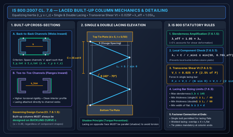
Regardless of the cross-sectional shape of the individual main components (channels, angles, plates, or rolled joists), all built-up compression members shall be designed using BUCKLING CURVE c ().
This accounts for fabrication residual stresses, welding/bolting distortions, and shear deformation in the transverse connector systems.
2.2 Laced Compression Members — Clause 7.6
1. Effective Slenderness Ratio () — Clause 7.6.1.5
To account for shear deformation of the lacing framework, the effective slenderness ratio of the column as a whole shall be taken as:
Where is the maximum actual slenderness ratio of the column as a whole (about the governing buckling axis).
2. Local Component Slenderness () — Clause 7.6.5.1
To prevent local buckling of an individual channel or angle between consecutive lacing connection points before overall column failure:
Where:
- is the center-to-center longitudinal spacing of lacing connections on one main component.
- is the minimum radius of gyration of the single individual component (e.g., of a single channel).
3. Design Transverse Shear Force () — Clause 7.6.3.1
Lacing systems shall be proportioned to resist a total design transverse shear force applied normal to the longitudinal axis of the member:
- If the column is subjected to external lateral loads or bending moments, the transverse shear from moments () must be added algebraically to .
- For a built-up column with parallel planes of lacing ( for two channels):
4. Lacing Bar Geometry & Sizing — Clause 7.6.2, 7.6.3 & 7.6.6
- Angle of Inclination (): (Standard practice: for single lacing; for double lacing).
- Maximum Slenderness of Lacing Flat (): Where is the unsupported length between inner end fasteners ( for single lacing), and for a flat bar.
- Minimum Thickness of Lacing Flat ():
- Minimum Width of Lacing Flat (): Where is the nominal diameter of the connecting bolt (e.g., for M16 bolts; for M20 bolts).
- End Tie Plates (Clause 7.6.8): Mandatory at both ends of laced columns and at points where lacing is interrupted:
2.3 Battened Compression Members — Clause 7.7
1. Effective Slenderness Ratio () — Clause 7.7.1.4
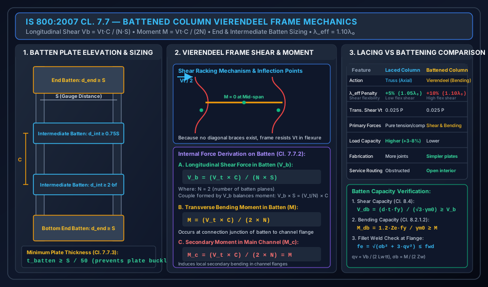
Because battens deform primarily in flexure (racking Vierendeel frame action) rather than axial truss action, shear deformation is significantly larger:
Where . (A slenderness amplification penalty!).
2. Local Component Slenderness () — Clause 7.7.3
3. Design Forces on Batten Plates — Clause 7.7.2
Battens must resist the transverse shear , which induces internal couples:
- Longitudinal Shear Force in Batten Plate ():
- Bending Moment in Batten Plate ():
Where:
- is the number of parallel planes of battens ().
- is the transverse distance between centroid of fastener/weld groups on the two components.
- is the center-to-center longitudinal spacing of battens.
4. Sizing Limits for Batten Plates — Clause 7.7.3
- End Battens (Tie plates at top and bottom):
- Intermediate Battens: Where is the flange width of the main component.
- Minimum Plate Thickness:
3. PHYSICAL MECHANICS & FUNDAMENTAL THEORY
================================================================================
              BUILT-UP COLUMN CROSS-SECTION OPTIMIZATION MECHANICS
================================================================================
          Single Channel (ISMC)                 Built-up Back-to-Back Channels
             y                                                y
             │                                                │
       ┌─────┴─────┐                                    ┌─────┴─────┐   ┌─────┴─────┐
       │   z-z     │                                    │   z-z     │   │   z-z     │
 ──────┼───────────┼────── z                     ───────┼───────────┼───┼───────────┼────── z
       │  (Major)  │                                    │           │ s │           │
       └─────┬─────┘                                    └─────┬─────┘   └─────┬─────┘
             │                                                │◄────────►│
          y-y (Weak Axis)                                     Distance s
       I_z = 6362.6 x 10⁴ mm⁴                                 I_z,tot = 2 * I_z1
       I_y = 310.8 x 10⁴ mm⁴                                  I_y,tot = 2 [I_y1 + A₁(s/2+Cy)²]
       Ratio I_z / I_y ≈ 20.5!                                By tuning s: I_y,tot = I_z,tot!
================================================================================
3.1 The Principle of Equal Radii of Gyration ()
In standard rolled steel channels, the major axis second moment of area is to times larger than the minor axis second moment of area .
- If a single channel is used as a column, it will buckle prematurely about its weak - axis at a tiny fraction of its major axis capacity.
- By placing two identical channels back-to-back or toe-to-toe and spacing them a distance apart, the parallel axis theorem shifts the channel areas away from the global - axis:
- By setting , we obtain:
- When is chosen such that , the column has equal buckling resistance in all directions, achieving material utilization!
3.2 Lacing vs Battening Structural Action
- Lacing System (Triangulated Truss Action): Lacing bars form a continuous triangulated truss. Transverse shear is resisted by pure axial tension and axial compression in the inclined bars. Axial stiffness is high, leading to minimal shear deformation (hence only a slenderness penalty: ).
- Batten System (Vierendeel Frame Action): Battens are horizontal rectangular plates without diagonal members. The system forms a Vierendeel rigid-jointed frame. Transverse shear must be resisted by internal bending and transverse racking shear. Because flexural racking is inherently more flexible than axial truss action, shear deformation is doubled (hence a slenderness penalty: ).
4. MATHEMATICAL DERIVATIONS & EXACT FORMULATIONS
4.1 Derivation of Lacing Bar Force ()
Consider a single lacing system inclined at angle to the longitudinal column axis.
- Let the total transverse design shear on the column be .
- For a two-channel column, there are parallel lacing planes (front face and back face). Transverse shear per plane:
- By horizontal force equilibrium at any transverse cross-section through the lacing system:
- For a double lacing system, two bars cross at each level, sharing the shear:
4.2 Derivation of Batten Longitudinal Shear () and Bending Moment ()
Consider a typical panel of a battened column bounded by two horizontal batten plates spaced apart:
- At mid-height between battens, points of inflection (zero moment) form in each column shaft.
- Cut a free-body diagram through the inflection points above and below a batten plate.
- The external transverse shear acting over the panel height generates an external overturning moment:
- This external moment must be equilibrated by the internal resisting couple formed by the longitudinal shear forces acting at the two ends of the batten plate separated by distance :
- Equating internal and external moments:
- Now consider the batten plate itself as a beam of span subjected to end vertical shears .
- A point of contraflexure exists at the mid-span of the batten plate ().
- The bending moment at the connection junction of the batten to the column shaft is:
- Concurrently, this same moment is transferred into the column shaft at the junction, producing local secondary flexure in the channel flanges:
5. STRUCTURAL DETAILING, GEOMETRY & FASTENER RULES
================================================================================
             IS 800:2007 STATUTORY DETAILING RULES SUMMARY
================================================================================
  Parameter                    Laced Columns (Cl. 7.6)          Battened Columns (Cl. 7.7)
  ─────────────────────────────────────────────────────────────────────────────
  Slenderness Amplification    λ_eff = 1.05 λ₀                  λ_eff = 1.10 λ₀
  Component Slenderness        λ₁ ≤ min(50, 0.70 λ_eff)         λ₁ ≤ min(50, 0.70 λ_eff)
  Transverse Shear Force       V_t = 0.025 P                    V_t = 0.025 P
  Inclination Angle θ          40° ≤ θ ≤ 70° (usually 45°)      90° (Perpendicular)
  Primary Forces in Connector  Pure Axial (Fc = Vt / 2 sin θ)   Shear (Vb) + Moment (M)
  Minimum Thickness            t ≥ L₁/40 (single), L₁/60 (dbl)  t ≥ S / 50
  Minimum Width / Depth        b ≥ 3 d (d = bolt dia)           d_end ≥ S; d_int ≥ 0.75 S
  Buckling Curve Designation   Curve c (α = 0.49)               Curve c (α = 0.49)
================================================================================
5.1 The "Shadow" Detailing Rule for Opposite Faces (Clause 7.6.4)
- When single lacing systems are provided on opposite faces of a column, the lacing bars must be parallel to each other (i.e. one face is the direct "shadow" of the other).
- If lacing bars are mirrored (sloping in opposite directions), an axial load on the column will cause the lacing bars on face 1 and face 2 to generate transverse shears in opposing senses, subjecting the column to severe torsional twisting!
6. HIGH-IMPACT VISUAL ARCHITECTURE
6.1 Laced Column Geometry, Spacing & Sizing Specifications
The diagram below illustrates the cross-sectional geometry of built-up channel columns, single vs double lacing elevations, statutory pitch , gauge distance , and statutory design limits per IS 800:2007 Cl. 7.6.
6.2 Battened Column Mechanics, Shear-Moment Distribution & Detailing
The diagram below illustrates Vierendeel frame shear racking, inflection point locations, free-body equilibrium yielding and , and capacity checks for intermediate and end batten plates per IS 800:2007 Cl. 7.7.
7. CODE NUANCES, EXCEPTIONS & DESIGN GUARDRAILS
7.1 Why Built-up Columns Are Prohibited on Buckling Curves a and b
Even if hot-rolled I-sections or tubes (which normally classify as Curve a or Curve b) are used to construct a built-up column:
- The assembly requires extensive stitch welding or continuous bolting along its length.
- Thermal contraction during fabrication introduces asymmetric longitudinal residual stresses ().
- Transverse connector flexibility introduces shear lag and secondary racking.
- Hence, IS 800:2007 Cl. 7.6.1.5 categorically demotes all built-up compression members to Curve c ().
7.2 Welded vs Bolted Lacing Connections
- Bolted Connections: IS 800 permits a single fastener at the end of each lacing bar flat. However, the bolt shear and bearing capacity must be strictly verified against .
- Welded Connections: When lacing flats are fillet welded to channel flanges, the lap length shall not be less than or , whichever is greater.
8. STANDARD WORKED NUMERICAL EXAMPLES
================================================================================
             VERIFIED NUMERICAL CALCULATION SUMMARY (IS 800:2007)
================================================================================
  Example 1: Laced Column Design (2 ISMC 300, P = 1200 kN, L = 8.0 m, Pinned-Pinned)
    • Channel Spacing: s = 185 mm back-to-back => r_y = 119.0 mm, r_z = 118.1 mm => r_min = 118.1 mm
    • Slenderness: λ₀ = 67.74 => λ_eff = 1.05 * 67.74 = 71.13 => f_cd = 150.43 MPa (Curve c)
    • Capacity: Pd = 1373.08 kN >= P = 1200 kN (SAFE!)
    • Lacing System (θ = 45°): S = 285 mm, C = 570 mm => λ₁ = 21.84 <= min(50, 49.79) (OK!)
    • Forces: V_t = 30.0 kN, V₁ = 15.0 kN => Lacing Bar Force Fc = 21.21 kN
    • Lacing Flat (50 x 12 mm): L₁ = 403 mm, λ_b = 116.35 <= 145 => f_cd = 87.47 MPa => Pd,flat = 52.48 kN >= 21.21 kN
    • Fastener: 1 No. M16 bolt (V_dsb = 29.01 kN >= 21.21 kN)

  Example 2: Battened Column Design (2 ISMC 300, P = 1000 kN, L = 6.0 m, Pinned-Pinned)
    • Slenderness: λ₀ = 50.80 => λ_eff = 1.10 * 50.80 = 55.88 => f_cd = 174.57 MPa => Pd = 1593.48 kN >= 1000 kN
    • Batten Layout: C = 800 mm => λ₁ = 30.65 <= limit 39.12 (OK!)
    • Forces: V_t = 25.0 kN => Longitudinal Shear V_b = 35.09 kN; Moment M = 5.00 kN-m
    • Sizing: End Batten 360 x 8 mm (d_end >= S = 285 mm); Intermediate Batten 280 x 8 mm (d_int >= 214 mm)
    • Batten Capacity: V_db = 293.92 kN >= 35.09 kN; M_db = 28.51 kN-m >= 5.00 kN-m (SAFE!)
    • Weld Check: 6 mm fillet weld => fe = 52.37 MPa <= f_wd = 189.37 MPa (SAFE!)

  Example 3: Direct Capacity Comparison: Laced vs Battened (2 ISMC 350, L = 7.0 m)
    • Base Slenderness: λ₀ = 51.24 (r_min = 136.6 mm)
    • Laced Column:    λ_eff = 53.81 => f_cd = 177.75 MPa => Pd = 1907.61 kN
    • Battened Column: λ_eff = 56.37 => f_cd = 173.82 MPa => Pd = 1865.49 kN
    • Advantage: Laced system carries +42.1 kN (+2.26%) higher axial capacity than Battened system!
================================================================================
8.1 Example 1: Comprehensive Design of a Laced Column
Problem Statement:
Design a built-up column consisting of two channel sections placed back-to-back to carry a factored axial compressive load . The unsupported length of the column is and both ends are pinned ().
Use Fe 410 steel (, , ).
Channels selected: 2 ISMC 300 @ 35.8 kg/m.
Properties of single ISMC 300:
, , , , , , , , .
Design a single lacing system inclined at with M16 Class 4.6 bolts.
Step-by-Step Mathematical Solution:
Step 1: Channel Spacing to Equalize Inertia
To maximize load-carrying efficiency, the spacing between the backs of the two channels is determined such that :
Adopt spacing back-to-back.
With :
Step 2: Column Slenderness & Axial Capacity
Actual slenderness:
Effective slenderness for laced column (IS 800 Cl. 7.6.1.5):
Euler critical stress:
Non-dimensional slenderness:
For built-up columns, use Buckling Curve c ():
Stress reduction factor :
Design compressive stress:
Design axial compressive strength:
Step 3: Lacing System Geometry & Layout
Adopt gauge distance from the back of the channel web.
Transverse distance between lacing gauge lines:
With inclination angle , the vertical spacing of lacing connections on each channel:
Check Local Component Slenderness (Cl. 7.6.5.1):
Step 4: Transverse Shear & Lacing Bar Force
Total transverse design shear force (Cl. 7.6.3.1):
Transverse shear per plane ( parallel faces):
Compressive force in each lacing flat:
Length of lacing bar between inner fasteners:
Step 5: Sizing & Capacity Verification of Lacing Flat
- Minimum Thickness (Cl. 7.6.3):
- Minimum Width (Cl. 7.6.2 for M16 bolts, ): Adopt lacing flat size: .
- Slenderness Check:
- Compressive Strength of Flat (Table 10 Curve c, ):
Step 6: Fastener Connection Design
Using M16 Class 4.6 bolts (, , , ):
- Shear capacity in single shear:
- Bearing capacity on flat / web:
- Bolt value: .
- Number of bolts required per end:
8.2 Example 2: Comprehensive Design of a Battened Column
Problem Statement:
Design a battened column using the same 2 ISMC 300 channels (, ) to carry a factored axial load . The column height is with pinned ends ().
Fe 410 steel (). Connect battens with fillet welds ().
Step-by-Step Mathematical Solution:
Step 1: Slenderness & Axial Capacity with Battens
Actual column slenderness:
Effective slenderness for battened column (IS 800 Cl. 7.7.1.4):
Using Buckling Curve c ():
Step 2: Batten Spacing
Component slenderness limit (Cl. 7.7.3):
Adopt center-to-center spacing .
Check: (OK!).
Step 3: Design Forces on Batten Plates
Total transverse shear:
Transverse distance between weld groups:
- Longitudinal shear force in batten plate:
- Bending moment in batten plate:
Step 4: Sizing of Batten Plates (Cl. 7.7.3)
- End Battens (Tie plates at top and bottom):
- Effective depth .
- Overall depth .
Adopt End Batten size: .
- Intermediate Battens:
- Effective depth .
- Depth .
Adopt Intermediate Batten depth: .
- Plate Thickness:
Step 5: Capacity Verification of Intermediate Batten ()
- Shear Capacity (Cl. 8.4):
- Bending Capacity (Cl. 8.2.1.2):
Step 6: Fillet Weld Connection Check
Connect batten to channel flange with fillet weld (). Length of weld along depth: . Two vertical weld lines per batten.
- Direct shear stress in weld:
- Section modulus of two weld lines:
- Bending stress in weld:
- Equivalent combined stress (Cl. 10.5.10):
8.3 Example 3: Comparative Capacity Study: Laced vs Battened System
Problem Statement:
A built-up column using 2 ISMC 350 channels placed toe-to-toe with clear spacing has an unsupported height (pinned ends, ).
Section properties: , .
Steel grade Fe 410 ().
Calculate and compare the design axial load carrying capacity when stabilized by:
- Single Lacing system.
- Batten Plate system.
Step-by-Step Computational Results:
Base slenderness:
1. Laced Column System (IS 800 Cl. 7.6.1.5):
Using Curve c ():
2. Battened Column System (IS 800 Cl. 7.7.1.4):
Using Curve c ():
Quantitative Synthesis:
Design Takeaway: For moderate slenderness (), lacing provides a modest capacity benefit. However, as slenderness increases (), the capacity advantage of lacing swells to to because the non-linear Euler curve drops much more steeply at higher !
9. COMPARATIVE ANALYSIS: LACED VS BATTENED COLUMNS
| Feature / Criterion | Laced Columns (IS 800 Cl. 7.6) | Battened Columns (IS 800 Cl. 7.7) |
|---|---|---|
| Structural Action | Triangulated pin-jointed truss action (pure axial forces) | Vierendeel rigid-jointed frame action (shear & bending) |
| Slenderness Penalty | (+5% increase) | (+10% increase) |
| Axial Load Capacity | Higher (typically +2% to +12% greater) | Lower due to higher shear flexibility |
| Connector Primary Forces | Axial Tension / Compression: | Longitudinal Shear and Moment |
| Component Flange Stress | No local secondary bending moments | Channel flanges subjected to secondary bending moments |
| Fabrication Complexity | Higher (more cutting, beveling, numerous bolts/welds) | Simpler (plain rectangular plates, fewer joints) |
| Architectural / Space Utility | Interior obstructed by diagonal cross-bars | Completely hollow interior (ideal for pipes, conduits, cables) |
| Recommended Application | Heavy civil structures, bridges, transmission towers | Building columns, architectural exposed columns, industrial sheds |
10. COMMON PITFALLS, SITE ERRORS & EXAMINATION TRAPS
10.1 Trap 1: The vs Slenderness Multiplier Confusion
- Candidates frequently swap the multipliers: remember Laced = 5% (triangles are rigid!), Battened = 10% (open rectangles are flexible!).
- In competitive examinations, forgetting to multiply by or before calculating leads directly to incorrect options!
10.2 Trap 2: The Transverse Shear Force Constant ()
- Remember that (), NOT and NOT .
- Furthermore, in a two-channel column, is split equally between the two parallel planes ().
10.3 Trap 3: Lacing Slenderness Limit vs Batten Thickness Limit
- Maximum slenderness of lacing flat: (frequently tested in SSC JE and ESE).
- Minimum thickness of batten plate: (NOT or ).
- Minimum thickness of lacing flat: (single) and (double).
11. MULTI-EXAM PREPARATION MATRIX
| Exam Pattern | High-Yield Topics & Question Formats | Key Formulas & Memory Aids |
|---|---|---|
| GATE CE | • Exact computation of longitudinal shear and moment • Optimum channel spacing for equal moments of inertia () • Combined stress check in fillet welds connecting battens |
|
| UPSC ESE | • Slenderness limits: vs • Lacing flat slenderness limit • Batten depth rules () • Transverse shear |
Lacing: End Batten: Int Batten: Thickness: |
| SSC JE / RRB JE | • Direct numerical on lacing flat thickness () • Minimum width of lacing flat () • Angle of inclination range () • Local slenderness limit |
Single: Double: Width: |
| State AE / JE | • Why built-up columns use Buckling Curve c • Shadow principle in lacing detailing • Force in lacing bar |
Curve c always () Opposite face lacing must be parallel |
12. COMPREHENSIVE REFERENCES & CROSS-LINKING
- Upstream Theory: 01_column_buckling_theory_and_curves.md — Buckling curves a, b, c, d, Perry-Robertson formulation, and section classification.
- Boundary Conditions: 02_effective_length_and_restraints.md — Effective length factors and frame stability.
- Downstream Module: 04_column_bases_slab_and_gusseted.md — Design of slab bases and gusseted bases (IS 800 Cl. 7.4).
- Primary Standards:
- Bureau of Indian Standards, IS 800:2007, General Construction in Steel — Code of Practice, Section 7.
- S. K. Duggal, Limit State Design of Steel Structures, McGraw Hill India.
- N. Subramanian, Design of Steel Structures, Oxford University Press.