Block Shear Failure Mechanisms & Formulations (IS 800:2007 Cl. 6.4)
In this chapter (4 topics)
On this page
- 1. Engineering Context & Overview
- 2. Physical Mechanics & Deformation Compatibility
- 2.1 The Physics of Block Tear-Out
- 2.2 The Strain & Displacement Compatibility Dilemma
- 3. Governing Indian Standard Code Provisions (IS 800:2007 Cl. 6.4)
- 3.1 Parameter Definitions
- 4. Mathematical Derivations & Area Calculation Rules
- 4.1 Shear Plane Geometry (Avg and Avn)
- 4.2 Tension Plane Geometry (Atg and Atn)
- 5. Geometric Topologies of Connections
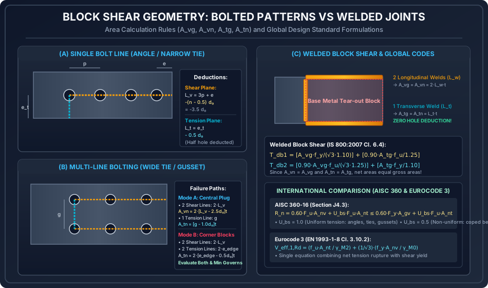
- 5.1 Topology A: Single Line of Bolts (Single Angle or Narrow Tie)
- 5.2 Topology B: Multi-Line Bolted Joint (Wide Plates & Gussets)
- 5.3 Topology C: Welded Connections
- 6. International Standards Comparison (IS 800 vs AISC 360 vs Eurocode 3)
- 7. Architectural SVG Technical Illustrations
- 7.1 Block Shear Failure Planes and Tear-out Modes
- 7.2 Bolted vs Welded Block Shear Geometry
- 8. Step-by-Step Pre-Calculated Numerical Problems
- Problem 1: Flat Plate Tension Member (Single Line Bolting)
- Problem 2: Single Angle Tension Member (ISA 100 × 75 × 8 mm)
- Problem 3: Multi-Line Bolted Tension Tie (Central U-Block vs Corner Blocks)
- 9. Comprehensive Summary & Comparative Analysis Table
- 10. Critical Practical Design & Detailing Guidelines
- 11. Site Pitfalls, Construction Traps & Inspection Failures
- 12. Competitive Examination Traps & Multiple-Choice Practice Questions
- Trap 1: The Fastener Hole Deduction Count
- Trap 2: Which Formula Governs?
- Trap 3: Welded Connection Net Area
- Practice Question 1 (GATE CE)
- Practice Question 2 (UPSC ESE)
- Practice Question 3 (SSC JE / State AE)
1. Engineering Context & Overview
In structural steel design, tension members and their end connections (such as truss ties, bracing members, roof truss hangers, and beam-to-column web connections) transfer heavy axial tensile forces into gusset plates, columns, or adjacent structural members through bolted or welded joints. Historically, structural designers checked tension members for two primary limit states:
- Gross Section Yielding () across the undisturbed member length to prevent excessive, unserviceable plastic elongation.
- Net Section Rupture () across the transverse line of bolt holes to prevent catastrophic tensile fracture.
However, full-scale experimental testing conducted in the 1970s and 1980s (most notably by Birkemoe and Gilmor, 1978; Hardash and Bjorhovde, 1985; and Kulak et al., 2001) revealed a distinct, highly destructive failure mode occurring at the connection perimeter: Block Shear Failure (also termed block tear-out).
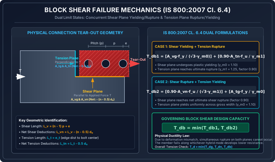
In a block shear failure, a whole block or "plug" of steel tears away from the member or the gusset plate along the boundary formed by the fastener holes or weld perimeter. The rupture surface consists of two distinct, orthogonal geometric planes:
- One or more shear planes oriented parallel to the direction of the applied tensile force.
- One tension plane oriented perpendicular to the direction of the applied tensile force.
Because block shear is a connection-specific limit state, it frequently governs the design capacity of short connections, heavily bolted gussets, and thin web elements. If ignored, an engineer might specify a member that satisfies both gross yielding and net rupture, yet suffers sudden, brittle tearing at a load substantially below either theoretical threshold. Consequently, modern structural standards—including the Indian Standard Code of Practice for General Construction in Steel (IS 800:2007, Clause 6.4), the American Institute of Steel Construction (AISC 360-16, Section J4.3), and the European Standard (Eurocode 3: EN 1993-1-8, Clause 3.10.2)—mandate rigorous evaluation of block shear capacity.
2. Physical Mechanics & Deformation Compatibility
2.1 The Physics of Block Tear-Out
When an axial tensile force acts on a connected plate or structural angle, the fasteners exert localized bearing forces against the edges of the holes. These bearing forces set up intense shear stresses along the longitudinal bolt lines and normal tensile stresses along the transverse line between the inner bolts and the edge:
- Shear Resistance along the longitudinal planes: As tension increases, the material between adjacent fastener holes and between the last fastener hole and the member edge experiences severe shear deformation. Resistance is mobilized by shear yielding and shear rupture along these longitudinal surfaces.
- Tensile Resistance along the transverse plane: Simultaneously, the material spanning across the bolt holes perpendicular to the force is subjected to direct normal tension.
       ═══════════════════════════════════════════════════════════
       Applied Force T  <===   [ Member / Tie Plate ]
       ══════════════════╦════════════════════════════════════════
                         ║  <-- Transverse Tension Plane (A_t)
                         o   o   o   o   o  (Fastener Holes)
       ------------------o---o---o---o---o------------------------
                         ^                  <-- Longitudinal Shear Plane (A_v)
                         └────── Torn-out Block ──────>
2.2 The Strain & Displacement Compatibility Dilemma
A fundamental mechanical question arises: Can the shear planes and the tension plane reach their ultimate rupture strengths simultaneously?
The answer is no. In structural steel, the ultimate rupture strain in pure tension () and the ultimate shear strain () do not develop concurrently at identical connection deformations.
- In typical bolted connections, the shear planes are significantly longer than the transverse tension plane (e.g., connection length versus edge distance ).
- Because the tension plane is short and stiff, it reaches its ultimate tensile strain () and begins necking/rupturing before the extensive longitudinal shear planes can reach their ultimate shear rupture strain ().
- Conversely, in certain connection geometries with short connection lengths and wide bolt spacing, the shear plane may reach rupture while the tension plane is only yielding.
To reflect this physical deformation mismatch, IS 800:2007 provides two concurrent limit-state formulations (dual modes) combining:
- Case 1: Shear Yielding along the shear plane combined with Tensile Rupture along the tension plane.
- Case 2: Shear Rupture along the shear plane combined with Tensile Yielding along the tension plane.
The true capacity is bounded by the lower of these two physical combinations.
3. Governing Indian Standard Code Provisions (IS 800:2007 Cl. 6.4)
Per IS 800:2007 Clause 6.4.1, the block shear strength of an end connection shall be taken as the smaller of:
3.1 Parameter Definitions
- = Gross area in shear along the plane parallel to the applied force.
- = Net area in shear along the plane parallel to the applied force (deducting bolt holes).
- = Gross area in tension along the plane perpendicular to the applied force.
- = Net area in tension along the plane perpendicular to the applied force (deducting bolt holes).
- = Characteristic yield strength of the material (e.g., for E250 / Fe 410).
- = Minimum ultimate tensile strength of the material (e.g., for Fe 410).
- = Partial safety factor against yielding of steel (IS 800:2007 Table 5).
- = Partial safety factor against ultimate tensile rupture (IS 800:2007 Table 5).
- = Factor from the von Mises yield criterion relating uniaxial tensile stress to pure shear stress ().
- = Empirical factor accounting for stress concentration, plastic necking restraint, and non-uniform shear stress distributions at fastener holes.
4. Mathematical Derivations & Area Calculation Rules
4.1 Shear Plane Geometry ( and )
Consider a line of fasteners arranged in the direction of force with pitch and end distance :
- The gross length of the shear plane is:
- The gross shear area is:
- When computing the net shear area , we must carefully account for hole deductions. The shear failure line passes through full bolt intervals and terminates at the center of the innermost bolt hole. At the free end, it cuts through the entire hole boundary up to the plate tip.
- The innermost bolt contributes half a hole ().
- The remaining intermediate bolts each contribute a full hole ().
- Total number of holes deducted along a single shear line:
- Therefore, the net shear length and net shear area are:
4.2 Tension Plane Geometry ( and )
Consider the transverse plane running from the innermost fastener line to the free plate edge (distance ):
- The gross transverse length is:
- The gross tension area is:
- The tension cut initiates from the centerline of the innermost fastener hole and extends to the edge. Thus, it cuts through exactly half of one hole ():
  Shear Plane Deduction:            Tension Plane Deduction:
        e          p           p
  ├──────────┼───────────┼───────────┤                  ┌─── Free Edge
  ░░░░░░░░░░░░░░░░░░░░░░░░░░░░░░░░░░░░                  │
  ───────┬───┬───────┬───┬───────┬───┐                  │
         │ o │       │ o │       │(o │ <── Innermost    │
  ───────┴───┴───────┴───┴───────┴───┤     Bolt (0.5 d₀)│
  │<────── 1.0 d₀ ──>│<─ 1.0 d₀ ─>│0.5│                 ▼
  Total shear holes deducted = 1.0 + 1.0 + 0.5 = 2.5    Tension cut: 0.5 d₀
5. Geometric Topologies of Connections
5.1 Topology A: Single Line of Bolts (Single Angle or Narrow Tie)
- Occurs in single angles connected by one leg or narrow flat tie plates.
- Single shear plane along the bolt line to the member tip.
- Single tension plane from the bolt line to the toe or lateral edge.
5.2 Topology B: Multi-Line Bolted Joint (Wide Plates & Gussets)
When fasteners are placed in multiple gauge lines (e.g., 2 lines of bolts with gauge ):
- Failure Mode 1 (Central U-Plug Tear-Out):
A central block between the two bolt lines pulls out.
- Two parallel shear planes: and .
- One transverse tension plane between the two lines: .
- Holes deducted in tension: The cut passes between two bolt centers, deducting two half-holes ():
- Failure Mode 2 (Two Corner Blocks):
Instead of the center pulling out, the two outer corners tear away towards the outer plate edges.
- Two parallel shear planes: .
- Two transverse tension planes to outer edges: and .
- Both candidate block shear topologies must be evaluated; the one producing the lower governs!
5.3 Topology C: Welded Connections
In welded lap joints or welded gusset attachments, block shear can occur by tearing out the base metal surrounding the weld group:
- Because no holes are drilled or punched in welded connections:
- The block shear equations simplify to:
- Welded connections possess substantially higher block shear resistance than bolted connections of identical size because zero cross-sectional area is lost to fastener perforations.
6. International Standards Comparison (IS 800 vs AISC 360 vs Eurocode 3)
| Design Parameter / Criterion | IS 800:2007 (India) | AISC 360-16 (USA) | Eurocode 3: EN 1993-1-8 (Europe) |
|---|---|---|---|
| Philosophy | Dual limit states; takes the minimum of both hybrid combinations. | Single unified equation with an upper bound limit. | Single unified equation combining tension rupture and shear yield. |
| Governing Formula | |||
| Stress Distribution Factor | Implicitly embedded in the factor applied to rupture terms. | Explicit tension stress factor : (uniform), (non-uniform). | Assumed uniform; eccentric effects handled by effective lengths. |
| Shear Yield Factor | (von Mises criterion) | (Tresca approximation) | |
| Partial Safety Factors | , | LRFD resistance factor | , |
| Hole Diameter for Area | Gross hole diameter (for M16-M24) | Nominal hole (total over bolt diameter) | Standard clearance hole |
7. Architectural SVG Technical Illustrations
7.1 Block Shear Failure Planes and Tear-out Modes
The following diagram illustrates the physical separation of a torn-out steel block, highlighting the longitudinal shear plane and transverse tension plane, along with the dual IS 800:2007 Cl. 6.4 formulations.
7.2 Bolted vs Welded Block Shear Geometry
This diagram details the exact geometric deduction rules for single-line bolting, multi-line bolting (central plug versus corner blocks), and welded connections, along with global code comparisons.
8. Step-by-Step Pre-Calculated Numerical Problems
Problem 1: Flat Plate Tension Member (Single Line Bolting)
A flat plate tension member of size of Fe 410 grade steel () is connected to a thick gusset plate using 4 bolts of M20 Grade 4.6 () arranged in a single line along the member length.
- Pitch
- End distance
- Transverse edge distance to the free plate edge
Determine:
- Block shear strength of the plate connection per IS 800:2007 Cl. 6.4.
- Gross yielding strength and net rupture strength .
- The governing design tensile strength of the connection.
Solution & Step-by-Step Calculations:
Step 1: Determine Geometric Dimensions of Shear and Tension Planes
- Number of bolts , thickness .
- Gross length of shear plane:
- Gross shear area:
- Net length of shear plane: The shear plane cuts through bolt holes.
- Net shear area:
- Gross length of tension plane:
- Gross tension area:
- Net length of tension plane: The tension cut extends from bolt center to the edge, deducting .
- Net tension area:
Step 2: Calculate Block Shear Capacities per IS 800:2007 Cl. 6.4
-
Case 1 (Shear Yielding + Tension Rupture):
-
Case 2 (Shear Rupture + Tension Yielding):
-
Governing Block Shear Capacity:
(Case 2 governs: Shear Rupture combined with Tension Yielding).
Step 3: Check Gross Section Yielding and Net Section Rupture
- Gross area of plate .
- Net area of plate across single hole line:
Step 4: Governing Tensile Capacity Evaluation
Engineering Takeaway: Block shear governs the capacity of the member! The plate yields at and ruptures across its net width at , but will catastrophically tear out at the connection at only .
Problem 2: Single Angle Tension Member (ISA 100 × 75 × 8 mm)
A single unequal angle tension member ISA 100 × 75 × 8 mm () is connected to a gusset plate through its longer leg () using 5 bolts of M20 Class 4.6 () in a single line.
- Pitch
- End distance
- Gauge line from heel (edge distance to toe )
- Outstanding leg width
Determine:
- Block shear strength of the connected leg.
- Net rupture strength accounting for shear lag per IS 800:2007 Cl. 6.3.3.
- Gross section yielding strength .
- The governing design tensile capacity .
Solution & Step-by-Step Calculations:
Step 1: Geometric Properties of the Connected Leg
- Total length of shear line along the bolt row:
- Gross shear area:
- Net length of shear line (deducting holes):
- Net shear area:
- Tension plane from bolt line to toe:
- Net tension plane length (deducting ):
Step 2: Calculate Block Shear Strengths per IS 800 Cl. 6.4
-
Case 1 (Shear Yield + Tension Rupture):
-
Case 2 (Shear Rupture + Tension Yield):
-
Governing Block Shear Capacity:
Step 3: Calculate Net Rupture with Shear Lag (IS 800 Cl. 6.3.3)
- Connection length .
- Shear lag width: .
- Section areas:
- Shear lag factor : (Check bounds: - Satisfied).
- Rupture capacity:
Step 4: Calculate Gross Section Yielding
Step 5: Overall Capacity Comparison
Critical Observation: Block shear reduces the usable design capacity of the angle from down to —a strength reduction! To eliminate this bottleneck, the designer must increase the pitch from to or increase end distance .
Problem 3: Multi-Line Bolted Tension Tie (Central U-Block vs Corner Blocks)
A tension plate tie of size (Fe 410 steel) is connected to a gusset with 6 bolts of M20 Class 4.6 () arranged in 2 gauge lines of 3 bolts each ( bolts).
- Longitudinal pitch
- Transverse gauge
- End distance
- Edge distance to outer edges
Evaluate:
- Block shear resistance for Mode A (Central U-Plug Pullout) between the two bolt lines.
- Block shear resistance for Mode B (Two Corner Blocks Tear-Out) to outer edges.
- Identify the critical block shear mode and compare with gross yielding and net rupture.
Solution & Step-by-Step Calculations:
Step 1: Failure Mode A (Central U-Plug Pullout)
- The central block is bounded by two shear lines along the bolt rows and one transverse tension line across the gauge :
- Gross length of one shear line: For two shear lines:
- Net length of one shear line (deducting holes): For two shear lines:
- Transverse tension plane across gauge : Holes deducted: Two half-holes from the two bolt lines ():
- Capacities for Mode A:
Step 2: Failure Mode B (Two Outer Corner Blocks Tear-Out)
-
Each corner block has one shear line () and one tension line to the outer edge ().
-
Two shear lines combined:
-
Tension planes: Two planes of gross width , each deducting :
-
Capacities for Mode B:
-
Comparison of Block Shear Modes:
Step 3: Comparison with Gross Yielding & Net Rupture
- Gross yielding:
- Net rupture across 2 holes:
- Overall governing strength: (Gross Section Yielding governs the design of this tie).
9. Comprehensive Summary & Comparative Analysis Table
| Parameter / Failure State | Gross Yielding () | Net Rupture () | Block Shear () |
|---|---|---|---|
| Governing Code Clause | IS 800:2007 Cl. 6.2 | IS 800:2007 Cl. 6.3 | IS 800:2007 Cl. 6.4 |
| Physical Mechanism | Plastic yielding along entire body length. | Tensile fracture across line of holes. | Block pullout/tearout along shear & tension planes. |
| Governing Strength Formula | or | ||
| Safety Factors Applied | Hybrid: (yield) & (rupture) | ||
| Governing Region | Body of member (away from joints). | Connection zone (critical cross section). | End connection boundary (fastener perimeter). |
| Ductility Level | High ductility (large elongations). | Brittle localized rupture. | Semi-brittle tear-out (moderate energy absorption). |
| Mitigation Measures | Increase gross cross-sectional area. | Stagger bolts, minimize hole diameter, weld instead of bolt. | Increase longitudinal pitch , end distance , or edge distance . |
10. Critical Practical Design & Detailing Guidelines
- Increasing Longitudinal Pitch (): The single most effective way to eliminate block shear vulnerability is to increase the longitudinal pitch between fasteners. Because the shear plane length scales as , increasing pitch from to expands both and directly, raising block shear resistance well above gross yielding.
- Generous End Distance (): Providing end distance (instead of the code minimum ) prevents premature tear-out past the outermost bolt hole.
- Bolt Layout Aspect Ratio: A long, narrow bolt group (large , small ) has high block shear resistance along its shear planes. Conversely, a wide, short bolt group (small , large ) is highly susceptible to longitudinal shear tear-out.
- Thickness of Gusset Plate vs Member: Block shear can occur in either the tension member or the gusset plate! In connections where the gusset plate is thinner than the member (), or where lower grade steel is used for the gusset, the gusset plate almost always governs block shear. Always verify block shear in both the connecting member and the gusset plate.
- Coped Beam Web Detailing: In beam-to-girder or beam-to-column connections where the top flange is coped (cut away) to allow flush framing, the top corner of the beam web is exposed to severe block shear tear-out. Increasing end distance and vertical bolt pitch in the web connection is essential.
11. Site Pitfalls, Construction Traps & Inspection Failures
- Oversized or Torched Holes on Site: When ironworkers ream or flame-cut bolt holes on site due to bolt mismatch, the hole diameter increases drastically (). This severely reduces both and , causing unanticipated block shear failures at service loads.
- Short End Distances Due to Misaligned Shearing: Fabrication shops shearing gusset plates with tolerances on the negative side often produce end distances . In tension members, an undersized end distance creates an immediate shear rupture plane at the outermost hole.
- Flame-Cut Edge Micro-Cracking: Rough flame-cut edges along the tension or shear perimeter act as stress raisers. Under fatigue or dynamic cyclic loading, micro-fissures from the flame cut propagate into the bolt holes, initiating rapid block tear-out.
- Ignoring Gusset Plate Tear-Out: Inspecting engineers frequently verify that the structural angle or channel member is adequately sized, but fail to compute block shear on the gusset plate itself. Gusset plate block shear has caused major structural collapses in industrial steel trusses.
12. Competitive Examination Traps & Multiple-Choice Practice Questions
Trap 1: The Fastener Hole Deduction Count
Trap: In competitive exams, students often deduct a full hole () per bolt on both the shear and tension planes. Correction:
- On the shear plane, intermediate bolts lose a full diameter, but the innermost bolt loses only half a diameter: deduct .
- On the tension plane from the bolt line to the edge, only half a hole () is deducted!
Trap 2: Which Formula Governs?
Trap: Assuming that (Shear Yield + Tension Rupture) always governs over (Shear Rupture + Tension Yield), or vice versa. Correction: In bolted connections with standard steel grades (Fe 410), Case 2 () frequently governs because the ultimate shear rupture term () often calculates lower than the gross shear yield term when hole deductions are substantial. Always compute both and take the minimum!
Trap 3: Welded Connection Net Area
Trap: Applying a hole deduction or empirical reduction factor to welded block shear. Correction: In welded connections, there are zero perforations. Hence and .
Practice Question 1 (GATE CE)
Q: In a bolted tension connection, the block shear capacity per IS 800:2007 is defined by two limit states. Which of the following statements is mathematically and mechanically CORRECT?
- (A) Both the shear plane and the tension plane achieve simultaneous ultimate tensile and shear rupture.
- (B) Mode 1 combines shear yielding with tension rupture, while Mode 2 combines shear rupture with tension yielding, with the minimum governing.
- (C) The factor is applied to the gross areas to account for stress concentrations.
- (D) Mode 1 combines gross tension yielding with gross shear yielding.
Answer: (B)
Explanation: IS 800:2007 Clause 6.4 explicitly recognizes that due to strain incompatibility, simultaneous rupture along both planes cannot occur. The strength is the minimum of (Shear Yield + Tension Rupture) and (Shear Rupture + Tension Yield). The factor applies exclusively to the rupture terms ( in , and in ).
Practice Question 2 (UPSC ESE)
Q: A single angle tension member connected by one leg to a gusset plate has 4 bolts in a single line parallel to the load. For block shear analysis, what is the total number of bolt hole diameters deducted to obtain the net shear area () and net tension area ()?
- (A) in shear, in tension
- (B) in shear, in tension
- (C) in shear, in tension
- (D) in shear, in tension
Answer: (B)
Explanation: The shear failure path traverses complete hole spaces and ends at the center of the innermost bolt: . The transverse tension failure path extends from the center of the innermost bolt to the toe/edge: exactly .
Practice Question 3 (SSC JE / State AE)
Q: A steel flat tie of Fe 410 grade () has a gross shear area and net tension area . Taking and , the block shear capacity for Mode 1 (Shear Yielding + Tension Rupture) is approximately:
- (A)
- (B)
- (C)
- (D)
Answer: (B)
Explanation:
Option (B) is exactly correct.