Laterally Supported Beams & Moment Capacity
In this chapter (4 topics)
On this page
- 1. TOPIC METADATA & OVERVIEW
- 2. CODE CLAUSES & STATUTORY PROVISIONS (IS 800:2007)
- 2.1 Criteria for Lateral Support (Restraint) — Clause 8.2.1
- 2.2 Cross-Section Classification for Flexure — Clause 3.7 & Table 2
- 2.3 Design Bending Strength under Low Shear (V ≤ 0.60 Vd) — Clause 8.2.1.2
- 2.4 Design Shear Strength (Vd) — Clause 8.4.1
- 2.5 Deflection Serviceability Guardrails — Table 6
- 3. PHYSICAL MECHANICS & FUNDAMENTAL THEORY
- 3.1 Mechanics of Plastic Hinge Formation
- 3.2 Shape Factor (S)
- 4. MATHEMATICAL DERIVATIONS & EXACT FORMULATIONS
- 4.1 Derivation of Plastic Modulus (Zp) for a Symmetrical I-Section
- 4.2 Derivation of the 1.20 Ze fracfyγm0 Upper Bound
- 5. STRUCTURAL DETAILING, DIAPHRAGMS & LATERAL RESTRAINTS
- 5.1 Maximum Permissible Unbraced Length (Lcr)
- 6. HIGH-IMPACT VISUAL ARCHITECTURE
- 6.1 Laterally Supported Cross-Section & Stress Distribution Evolution
- 6.2 Moment-Rotation Hinge Behavior & Deflection Limits
- 7. CODE NUANCES, EXCEPTIONS & DESIGN GUARDRAILS
- 7.1 Web Local Buckling Check (d/tw ≤ 67 ε)
- 7.2 The Low Shear vs High Shear Criterion (V ≤ 0.60 Vd)
- 8. STANDARD WORKED NUMERICAL EXAMPLES
- 8.1 Example 1: Complete Design of a Laterally Supported Floor Secondary Beam
- 8.2 Example 2: Comparative Study — Impact of Section Classification on Md
- 8.3 Example 3: Cantilever Beam Upper Bound Comparison
- 9. COMPARATIVE ANALYSIS: CROSS-SECTION BEHAVIOR MODES
- 10. COMMON PITFALLS, SITE ERRORS & EXAMINATION TRAPS
- 10.1 Trap 1: Confusing Factored vs Unfactored Loads for Deflection
- 10.2 Trap 2: Forgetting the 1.20 Ze fy / γm0 Cap
- 10.3 Trap 3: Rolled Section Shear Area (Av = h · tw)
- 11. MULTI-EXAM PREPARATION MATRIX
- 12. COMPREHENSIVE REFERENCES & CROSS-LINKING
1. TOPIC METADATA & OVERVIEW
- Subject: Design of Steel Structures (IS 800:2007)
- Module: Chapter 04 — Design of Beams and Flexural Members
- Topic ID: STEEL-04-01
- Topic Title: Laterally Supported Beams, Section Classification & Plastic Moment Capacity (IS 800:2007 Cl. 8.2) — INAUGURAL TOPIC OF CHAPTER 04!
- Prerequisites: STEEL-03-01 (Perry-Robertson & Section Classification Classes 1-4)
- Target Examinations: GATE CE, UPSC ESE, SSC JE, RRB JE, State PSC AE/JE
- Key Reference Codes: IS 800:2007 (Cl. 8.2.1, 8.2.1.2, 8.4.1, Table 2, Table 6), SP 6(1), AISC 360-16
2. CODE CLAUSES & STATUTORY PROVISIONS (IS 800:2007)
2.1 Criteria for Lateral Support (Restraint) — Clause 8.2.1
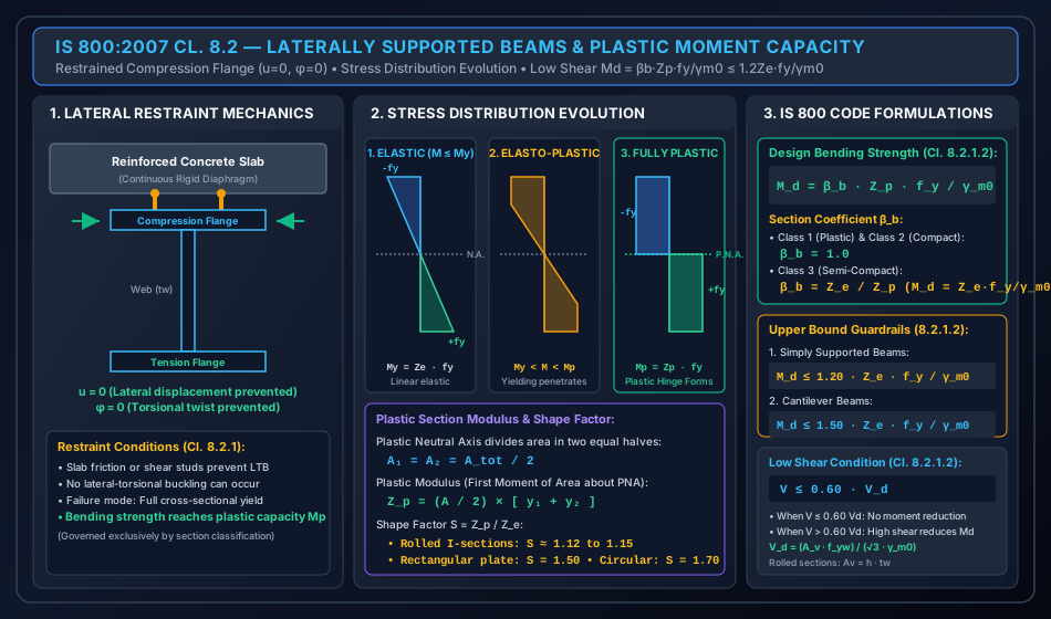
A beam is designated as laterally supported (or laterally restrained) when its compression flange is prevented from translating laterally and twisting about its longitudinal axis throughout its span:
- In building structures, lateral support is provided when:
- A cast-in-situ reinforced concrete floor slab rests directly on the compression flange, with or without shear connectors (composite action or frictional embedment).
- Closely spaced secondary transverse cross-beams or floor joists frame rigidly into the compression flange at intervals .
- Precast slab panels with concrete topping and positive mechanical anchoring.
- Fundamental Implication: In laterally supported beams, Lateral-Torsional Buckling (LTB) is completely prevented. The beam achieves its full in-plane flexural strength governed exclusively by cross-sectional yielding and plasticity!
2.2 Cross-Section Classification for Flexure — Clause 3.7 & Table 2
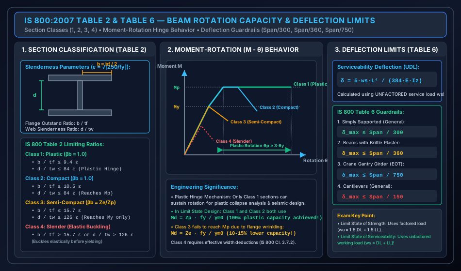
The flexural capacity of a steel section is governed by the width-to-thickness ratios of its individual plate elements (flange outstand and clear web depth ):
| Section Class | Description | Flange Outstand Ratio () | Web Slenderness Ratio () | Bending Capacity () | Rotation Capacity |
|---|---|---|---|---|---|
| Class 1 | Plastic | Develops plastic hinge with rotation capacity for plastic collapse analysis | |||
| Class 2 | Compact | Develops full plastic moment , but local buckling prevents large rotation | |||
| Class 3 | Semi-Compact | Extreme fibers reach yield , but local buckling prevents developing | |||
| Class 4 | Slender | Buckles elastically before extreme fiber yields (requires effective width deductions) |
2.3 Design Bending Strength under Low Shear () — Clause 8.2.1.2
When the factored design shear force does not exceed of the design plastic shear resistance of the cross-section ():
Where:
- for Class 1 (Plastic) and Class 2 (Compact) sections.
- for Class 3 (Semi-Compact) sections (which reduces the equation directly to ).
- is the plastic section modulus about the major bending axis (-).
- is the elastic section modulus about the major bending axis (-).
- is the partial safety factor for material yield strength.
- is the statutory upper bound for simply supported beams to avoid excessive plastic deformation under service loads.
2.4 Design Shear Strength () — Clause 8.4.1
The design plastic shear resistance of a section is:
Where the shear area is calculated as:
- For rolled I and H sections: (where is overall depth and is web thickness).
- For welded I sections: (where is clear web depth between flanges).
- For rolled channels: .
- Low Shear Threshold: If , shear does not reduce flexural capacity.
- High Shear Condition: If , high shear interaction reduces moment capacity to (IS 800 Cl. 8.2.1.3).
2.5 Deflection Serviceability Guardrails — Table 6
Deflection calculations are carried out under unfactored service loads ():
- For a simply supported beam with uniformly distributed load:
- Statutory Limits (Table 6):
- Simply supported beams supporting non-fragile finishes: .
- Beams supporting brittle plaster / masonry finishes: .
- Overhead crane gantry girders: (manually operated) or (electric overhead traveling crane).
- Cantilevers: (general) or (brittle finishes).
3. PHYSICAL MECHANICS & FUNDAMENTAL THEORY
================================================================================
             CROSS-SECTION STRESS EVOLUTION IN LATERALLY SUPPORTED BEAMS
================================================================================
       Elastic Stage (M ≤ My)       Elasto-Plastic (My < M < Mp)    Fully Plastic (M = Mp)
            -fy                          -fy                           -fy
        ◄────────►                   ◄────────►                    ◄────────►
       ┌─────────┐                  ┌─────────┐                   ┌─────────┐
       │ \       │                  │█\       │                   │█████████│ Comp.
 ──────┼──\──────┼────── N.A. ──────┼──\──────┼────── N.A.  ──────┼─────────┼────── P.N.A.
       │   \     │                  │   \█    │                   │█████████│ Tension
       └─────────┘                  └─────────┘                   └─────────┘
        ◄────────►                   ◄────────►                    ◄────────►
            +fy                          +fy                           +fy
       Linear Triangular             Yielding Spreads Inward       Equal Area Rectangles
       M = Ze · fy                   My < M < Mp                   Mp = Zp · fy
================================================================================
3.1 Mechanics of Plastic Hinge Formation
In a laterally supported steel beam under progressive bending:
- Elastic Limit (): Stress varies linearly from zero at the neutral axis to extreme fiber stress . When extreme fibers reach yield stress , the yield moment is reached:
- Elasto-Plastic Stage (): As load increases, outer fibers yield plastically at constant stress (assuming elastic-perfectly plastic stress-strain curve). The yield zone penetrates deeper into the section toward the neutral axis.
- Fully Plastic Stage ():
Every fiber across the entire cross-section yields simultaneously: on the tension side and on the compression side.
- For longitudinal axial force equilibrium ():
- The Plastic Neutral Axis (P.N.A.) divides the total cross-sectional area into two equal halves!
- The plastic moment of resistance is:
- Where is the Plastic Section Modulus, and are the distances from the PNA to the centroids of the compressive and tensile areas.
3.2 Shape Factor ()
The shape factor represents the plastic reserve strength of a cross-section beyond its initial yield:
- Rolled I-sections (ISMB, ISHB, etc.): (Flanges carry of moment, so yielding spreads rapidly through the thin web, yielding only a plastic reserve).
- Solid Rectangular Sections: ( plastic reserve!).
- Solid Circular Sections: .
- Diamond / Rhombus Section: .
4. MATHEMATICAL DERIVATIONS & EXACT FORMULATIONS
4.1 Derivation of Plastic Modulus () for a Symmetrical I-Section
Consider a symmetrical rolled I-section with depth , flange width , flange thickness , and web thickness :
- By symmetry, the Plastic Neutral Axis (PNA) coincides with the mid-depth centroidal axis ().
- Area of one half (compression side):
- First moment of area of the compression flange about PNA:
- First moment of area of the compression half-web about PNA:
- By symmetry, tension side contributes an identical moment:
4.2 Derivation of the Upper Bound
Why does IS 800:2007 Cl. 8.2.1.2 cap at for simply supported beams?
- Under factored limit state loads, .
- Under unfactored working loads (serviceability limit state):
- If a section with a large shape factor (e.g. built-up plate beam or rectangular bar with ) were designed up to : This approaches yield at service loads, causing visible unrecoverable plastic deformations and deflection issues!
- By capping : This strictly guarantees that under ordinary working loads, extreme fiber stress never exceeds of yield stress (), ensuring purely elastic behavior without permanent set!
- For cantilevers, plastic hinges form at the support where deformation is localized, so the code relaxes the limit to .
5. STRUCTURAL DETAILING, DIAPHRAGMS & LATERAL RESTRAINTS
================================================================================
             PRACTICAL METHODS OF ACHIEVING LATERAL RESTRAINT
================================================================================
  Method 1: Concrete Slab with Shear Studs    Method 2: Transverse Cross-Beams
       Concrete Slab                                 Floor Joist / Cross Beam
   ┌──────────────────────┐                       ┌──────────┐
   │██████████████████████│                       │          │
   └──────────┬───────────┘                       └────┬─────┘ Framing into
              │ Shear Stud                             │       top flange
         ┌────┴────┐                              ┌────┴────┐
         │         │                              │         │
         │  Steel  │                              │  Steel  │
         │  Beam   │                              │  Beam   │
         │         │                              │         │
         └─────────┘                              └─────────┘
================================================================================
5.1 Maximum Permissible Unbraced Length ()
If continuous lateral support by a slab is absent, discrete lateral braces (cross-beams or bracings) must be provided at spacing . To qualify as laterally supported without LTB reduction, IS 800 Cl. 8.2.2 requires:
Where is the radius of gyration of the section about its minor axis. If , the member can be designed as laterally supported!
6. HIGH-IMPACT VISUAL ARCHITECTURE
6.1 Laterally Supported Cross-Section & Stress Distribution Evolution
The diagram below illustrates the physical assembly of a laterally supported beam, restraint mechanics (), and the three-stage cross-sectional stress progression from elastic to fully plastic.
6.2 Moment-Rotation Hinge Behavior & Deflection Limits
The diagram below illustrates the cross-section classification boundaries (Table 2), moment-rotation () response curves for Classes 1 to 4, and deflection serviceability limits per Table 6.
7. CODE NUANCES, EXCEPTIONS & DESIGN GUARDRAILS
7.1 Web Local Buckling Check ()
Per IS 800:2007 Cl. 8.4.2.1:
- If , the web is immune to shear buckling, and shear strength is governed solely by plastic shear yielding ().
- If , the web may buckle in shear elastically or inelastically before yielding, requiring post-buckling shear assessment (Cl. 8.4.2.2, detailed in Topic 02).
- Standard Indian rolled I-beams (ISMB, ISHB) almost universally have , making them completely immune to web shear buckling!
7.2 The Low Shear vs High Shear Criterion ()
- When factored shear force , longitudinal flexural stresses and shear stresses do not interact significantly. The full plastic moment is available.
- When , high shear stresses cause plastic yielding in the web, reducing the web's contribution to resisting bending moments.
8. STANDARD WORKED NUMERICAL EXAMPLES
================================================================================
             VERIFIED NUMERICAL CALCULATION SUMMARY (IS 800:2007)
================================================================================
  Example 1: Laterally Supported Floor Beam (ISMB 400, Span = 6.0 m, RC Slab)
    • Total Loads: Dead = 15 kN/m, Live = 20 kN/m, Self-weight = 0.604 kN/m => wu = 53.406 kN/m
    • Factored Forces: Mu = 240.33 kN-m, Vu = 160.22 kN
    • Section Classification: b/tf = 4.375 <= 9.4, d/tw = 38.20 <= 84 => Class 1 Plastic (βb = 1.0)
    • Shear Check: Vd = 467.13 kN => 0.60 Vd = 280.28 kN >= Vu = 160.22 kN => LOW SHEAR (OK!)
    • Moment Capacity: Md = 1.0 * 1176.2e3 * 250 / 1.10 = 267.32 kN-m (<= limit 278.97 kN-m) >= Mu = 240.33 kN-m (SAFE!)
    • Deflection: Under unfactored ws = 35.604 kN/m => δ = 14.68 mm <= limit Span/300 = 20.0 mm (SAFE!)

  Example 2: Influence of Section Classification on Bending Capacity
    • Section A (Class 1 & 2): βb = 1.00 => Md = 207.27 kN-m
    • Section B (Class 3): βb = Ze / Zp = 0.8772 => Md = 181.82 kN-m
    • Capacity Penalty: -12.28% reduction in flexural capacity due to local flange wrinkling!

  Example 3: Cantilever Beam Upper Bound Comparison
    • Simply Supported Upper Bound: 1.20 Ze fy / γm0 = 136.36 kN-m
    • Cantilever Upper Bound:        1.50 Ze fy / γm0 = 170.45 kN-m
    • Benefit: Cantilevers gain +25.0% higher permissible plastic capacity before upper-bound capping!
================================================================================
8.1 Example 1: Complete Design of a Laterally Supported Floor Secondary Beam
Problem Statement:
A simply supported floor secondary beam has an effective span of .
The beam carries a working imposed live load of and a working dead load of from a reinforced concrete floor slab and floor finishes (excluding self-weight).
The compression flange of the beam is continuously cast into the slab, providing complete lateral restraint.
Steel grade Fe 410 (, , ).
Design and verify the suitability of an ISMB 400 @ 61.6 kg/m section for flexure, shear, and serviceability deflection.
Properties of ISMB 400:
, , , , , , , , self-weight .
Step-by-Step Mathematical Solution:
Step 1: Factored Design Loads & Internal Force Resultants
Total working (service) load:
Factored ultimate design load ():
Maximum factored bending moment at mid-span:
Maximum factored shear force at supports:
Step 2: Cross-Section Classification (IS 800 Table 2)
Yield stress parameter:
- Flange outstand ratio: Since .
- Web slenderness ratio: Since . The entire cross-section is Class 1 (Plastic) .
Step 3: Shear Capacity & Low Shear Verification (Clause 8.4.1)
Shear area for rolled I-section:
Design plastic shear capacity:
Low shear threshold:
Since :
Step 4: Design Bending Strength () (Clause 8.2.1.2)
For a Class 1 section under low shear:
Check statutory upper bound for simply supported beams:
Since , the governing design bending strength is:
Check against factored moment:
Step 5: Serviceability Deflection Verification (Table 6)
Deflection under unfactored service load :
Permissible deflection limit (Table 6 for general beam):
Since :
8.2 Example 2: Comparative Study — Impact of Section Classification on
Problem Statement:
A rolled beam has an elastic section modulus and plastic section modulus (Shape factor ). Steel grade Fe 410 (, ).
Compare the design bending strength under low shear if the section is:
- Classified as Class 1 (Plastic) or Class 2 (Compact).
- Classified as Class 3 (Semi-Compact) due to thinner flange outstand.
Step-by-Step Computational Results:
- Case A: Class 1 (Plastic) or Class 2 (Compact) Section (): Check upper bound:
- Case B: Class 3 (Semi-Compact) Section ():
- Synthesis: Insight: Class 3 sections lose the entire plastic reserve (), failing when extreme fibers reach yield due to premature local plate wrinkling.
8.3 Example 3: Cantilever Beam Upper Bound Comparison
Problem Statement:
A built-up laterally supported cantilever beam has and (Shape factor ). Fe 410 steel (, ).
Compute the permissible design bending capacity and compare the upper bound for:
- Simply supported beam condition.
- Cantilever beam condition.
Step-by-Step Computational Results:
Plastic capacity:
- Simply Supported Beam Upper Bound (): Governing simply supported capacity:
- Cantilever Beam Upper Bound (): Governing cantilever capacity:
- Synthesis:
9. COMPARATIVE ANALYSIS: CROSS-SECTION BEHAVIOR MODES
| Attribute | Class 1 (Plastic) | Class 2 (Compact) | Class 3 (Semi-Compact) | Class 4 (Slender) |
|---|---|---|---|---|
| Flange Limit () | ||||
| Web Limit () | ||||
| Moment Capacity () | ||||
| Section Factor () | ||||
| Hinge Rotation () | High () | Limited () | Zero (buckles at yield) | Zero (buckles before yield) |
| Plastic Analysis Use | Permitted & Recommended | Prohibited | Prohibited | Prohibited |
10. COMMON PITFALLS, SITE ERRORS & EXAMINATION TRAPS
10.1 Trap 1: Confusing Factored vs Unfactored Loads for Deflection
- Candidates frequently compute deflection using factored load .
- Fatal Error: Table 6 deflection criteria represent Limit State of Serviceability, which MUST be computed using unfactored working loads ()! Using factored loads overestimates deflection by and causes unnecessary member upsizing.
10.2 Trap 2: Forgetting the Cap
- In competitive examinations, when a section has a shape factor (e.g. welded built-up sections or channels), students often take .
- If , the capacity is capped at !
10.3 Trap 3: Rolled Section Shear Area ()
- For rolled I-sections, IS 800 specifies shear area as , where is the overall depth of the section (), NOT the clear web depth !
- Clear web depth is only used for welded plate girders.
11. MULTI-EXAM PREPARATION MATRIX
| Exam Pattern | High-Yield Topics & Question Formats | Key Formulas & Memory Aids |
|---|---|---|
| GATE CE | • Exact computation of and check • Table 2 section classification () • Low shear vs high shear boundary () |
|
| UPSC ESE | • Direct memory retrieval of Table 6 deflection limits (Span/300, Span/360, Span/750) • Shape factor values (I-section 1.14, Rectangle 1.5, Circle 1.7) • Criteria for lateral support () |
General SS: Brittle plaster: EOT Crane: |
| SSC JE / RRB JE | • Plastic Neutral Axis definition () • Definition of shape factor • Shear area of rolled beam |
PNA divides area in half (rolled) |
| State AE / JE | • Meaning of (Plastic/Compact) vs (Semi-compact) • Cantilever upper bound |
Cantilever: SS Beam: |
12. COMPREHENSIVE REFERENCES & CROSS-LINKING
- Upstream Module: 04_column_bases_slab_and_gusseted.md — Slab and gusseted base design.
- Downstream Module: 02_shear_capacity_and_high_shear.md — Design for shear capacity, high shear interaction (), and web post-buckling.
- Primary Standards:
- Bureau of Indian Standards, IS 800:2007, General Construction in Steel — Code of Practice, Section 8.2 and Tables 2 & 6.
- S. K. Duggal, Limit State Design of Steel Structures, McGraw Hill India.
- N. Subramanian, Design of Steel Structures, Oxford University Press.