Shear Lag Effect & Angles under Axial Tension (IS 800:2007 Cl. 6.3.3)
In this chapter (4 topics)
On this page
- 1. Topic Overview & Engineering Context
- 2. Governing Codes, Standards & Design Philosophy
- 3. Kinematics, Mechanics & Fundamental Principles
- 3.1 The Mechanics of Shear Lag in Un-symmetrical Profiles
- 3.2 Influence of Connection Detailing
- 4. Mathematical Formulations & Derivations
- 4.1 Division of Angle Cross-Sectional Areas
- 4.2 Shear Lag Width (bs)
- 4.3 Connection Length (Lc)
- 5. IS 800:2007 Design Specifications & Detailing Rules
- Table 1: Code Provisions for Angle Tension Members (IS 800:2007 Cl. 6.3.3)
- 6. Engineering Diagrams & Visual Explanations
- Figure 1: Shear Lag Mechanics & Stress Distribution in Tension Angles
- Figure 2: Shear Lag Width (bs) & Connection Length (Lc) Geometry
- 7. Step-by-Step Design Procedures & Workflows
- 7.1 Workflow: Evaluation of Angle Tension Member Capacity
- 8. Solved Numerical Examples (Pre-Calculated & Multi-Step)
- Problem 1: Bolted Single Angle Tension Member (ISA 90 × 60 × 8 mm)
- Problem 2: Welded Single Angle Tension Member Comparison
- Problem 3: Double Angles Back-to-Back — Tack Bolting & Design
- 9. Common Pitfalls, Edge Cases & Failure Modes
- 10. Exam-Specific Focus Points & Rapid Revision Notes
- 10.1 Quick Revision Formula Card
- 10.2 Examination Nuances
- 11. Practice Problems & Self-Assessment Question Bank
- 12. Bibliographic References & Standard Codes
1. Topic Overview & Engineering Context
In structural steel design, angle sections (equal and unequal angles) are the most widely used profile for tension members in roof trusses, communication towers, electrical transmission line towers, and bracing systems due to their ease of fabrication, direct bolting/welding to gusset plates, and geometric compactness. However, when an angle section is connected through only one of its legs to a gusset plate (with the other leg remaining unconnected or "outstanding"), the tensile load transfer into the member becomes non-uniform.
This non-uniform stress distribution is known as the shear lag effect:
- Near the connection, the tensile force is transmitted directly into the connected leg through the fasteners or welds.
- The outstanding leg receives tensile stress indirectly, via transverse in-plane shear flowing through the corner heel junction of the angle.
- Because steel has finite shear stiffness (), shear deformations cause the longitudinal tensile strains and stresses in the outstanding leg to "lag" behind those in the connected leg.
- As a result, the stress is concentrated near the fastener line in the connected leg and decays sharply toward the tip of the outstanding leg. At ultimate rupture, the outstanding leg does not develop its full tensile strength.
To quantify this loss of efficiency, IS 800:2007 Clause 6.3.3 formulates the design net rupture strength () by decomposing the angle into a connected leg component that ruptures at ultimate strength () and an outstanding leg component that yields at reduced efficiency governed by a shear lag factor ():
                 +-------------------------------------------------------------+
                 |            AXIAL TENSION IN ANGLE SECTIONS                  |
                 +-------------------------------------------------------------+
                                               |
                 +-----------------------------+-----------------------------+
                 |                                                           |
                 v                                                           v
     [CONNECTED LEG (Anc)]                                       [OUTSTANDING LEG (Ago)]
     * Direct mechanical attachment                              * No direct connection
     * Governed by Net Rupture:                                  * Governed by Shear Lag Yielding:
       T1 = (0.90 * Anc * fu) / γm1                                T2 = (β * Ago * fy) / γm0
     * High stress concentration                                 * Stress decays toward tip
2. Governing Codes, Standards & Design Philosophy
The design of structural steel angle tension members subjected to shear lag is codified in IS 800:2007 (Limit State Method):
- Clause 6.3.3 (Rupture Strength of Angles Connected through One Leg):
- The design rupture strength of a single angle connected by one leg (either bolted or welded) is:
- The shear lag factor is calculated as: subject to codified boundary limits: (For Fe 410 steel with : the upper bound is .)
- Simplified Preliminary Design Alternative (Cl. 6.3.3):
Alternatively, the code permits a simplified expression for preliminary sizing:
where is the total net area of the angle, and is an empirical shear lag factor:
- for 1 or 2 bolts in line.
- for 3 bolts in line.
- for 4 or more bolts in line, or for welded connections.
- Double Angles Connected Back-to-Back (IS 800 Cl. 6.3.3 & Cl. 10.2.5.5):
- When two angles are placed back-to-back on opposite sides of a gusset plate, out-of-plane eccentricity is eliminated.
- To ensure the two angles act as an integrated structural unit, tack bolting / tack welding is mandatory at regular intervals:
- When properly tack-bolted on opposite sides of the gusset plate, is twice the capacity of a single angle.
3. Kinematics, Mechanics & Fundamental Principles
3.1 The Mechanics of Shear Lag in Un-symmetrical Profiles
Consider a single angle ISA connected to a gusset plate along leg :
- Load Introduction: The external axial tension is applied via the gusset plate directly into the connected leg.
- Internal Shear Flow: To equilibrate the total member cross-section, load must diffuse from the connected leg into the outstanding leg across the heel junction. This transfer occurs exclusively through longitudinal shear stresses ().
- Shear Strain Lag: The shear strain creates a distortion profile where longitudinal displacements in the outstanding leg lag behind displacements in the connected leg:
- Stress Profile: At sections near the connection, the tensile stress is highest at the line of fasteners in the connected leg, and drops exponentially toward the tip of the outstanding leg.
- Effective Width Concept: At ultimate failure, the connected leg reaches its full plastic net rupture strength (), whereas the outstanding leg contributes only an effective portion of its yield capacity ().
       [Gusset]  Connected Leg (b1)        Corner Heel       Outstanding Leg (b2 = w)
          ||    +-------------------------+-----------------------------------------+
          ||    |  (o) Bolt Line          |                                         |
          ||    |  Peak Stress σmax       |                                         |
          ||    |=========================|===========\                             |
          ||    |                         |            \   Decaying Stress          |
          ||    |                         |             \                           |
          ||    +-------------------------+--------------\--------------------------+
                                                          \--> Minimum Stress σmin at Tip
3.2 Influence of Connection Detailing
- Connection Length (): The longer the connection (more bolts or longer weld lines), the greater the longitudinal distance available for shear stresses to diffuse into the outstanding leg. Consequently, larger increases and minimizes shear lag loss.
- Outstand Width (): Wider outstanding legs require shear to travel farther to reach the tip. Thus, smaller reduces shear lag.
- Engineering Golden Rule: To minimize shear lag in unequal angles, always connect the longer leg to the gusset plate ().
4. Mathematical Formulations & Derivations
4.1 Division of Angle Cross-Sectional Areas
To prevent double-counting the corner junction of thickness , the angle cross-section is divided symmetrically at the root:
- Net Area of Connected Leg ():
- For a bolted angle with one line of holes:
- For a welded angle (no hole deduction):
- Gross Area of Outstanding Leg ():
- Total Gross Area ():
4.2 Shear Lag Width ()
The parameter represents the unfolded distance from the extreme free edge of the outstanding leg to the nearest line of fasteners in the connected leg:
- Bolted Connection:
where:
- : Width of the outstanding leg.
- : Gauge distance from the heel of the angle to the center of the bolt hole in the connected leg.
- : Thickness of the angle.
- Welded Connection: Since fillet welds are placed along both the heel and the toe of the connected leg, the load enters across the full width of the connected leg. Hence, (or the distance is zero from the heel weld), yielding:
4.3 Connection Length ()
- Bolted Connection: Distance between the centers of the first and last bolt in the joint measured parallel to the direction of tension: where is the number of bolts aligned in the direction of load, and is the pitch. (Note: If , , in which case is governed by the codified lower bound .)
- Welded Connection: Length of the weld along the load direction. If unequal welds are provided at the heel () and toe (), is taken as the length of the longer weld ().
5. IS 800:2007 Design Specifications & Detailing Rules
Table 1: Code Provisions for Angle Tension Members (IS 800:2007 Cl. 6.3.3)
| Parameter | Bolted Connection | Welded Connection | Code Reference |
|---|---|---|---|
| Connected Leg Net Area () | Cl. 6.3.3 | ||
| Outstanding Leg Area () | Cl. 6.3.3 | ||
| Shear Lag Width () | Cl. 6.3.3 | ||
| Connection Length () | Length of longer longitudinal weld | Cl. 6.3.3 | |
| Shear Lag Factor () | Cl. 6.3.3 | ||
| Lower Bound on | Cl. 6.3.3 | ||
| Upper Bound on | Cl. 6.3.3 | ||
| Preliminary Design Factor () | (1-2 bolts), (3 bolts), ( bolts) | Cl. 6.3.3 | |
| Tack Bolting Spacing | (Tension) / (Compression) | (Tension) | Cl. 10.2.5.5 |
6. Engineering Diagrams & Visual Explanations
Figure 1: Shear Lag Mechanics & Stress Distribution in Tension Angles
+----------------------------------------------------------------------------------------------------+
|                               SHEAR LAG MECHANICS IN SINGLE ANGLES                                 |
|                                                                                                    |
|    Connected Leg (Anc)                       Outstanding Leg (Ago)                                 |
|    +-----------------------------+           +---------------------------------------+             |
|    |                             |   Heel    |                                       |             |
|    |      (o) Bolt Line          |  Junction |                                       |             |
|    |                             |==== x ====|                                       |             |
|    |  Direct Load Introduction   |           |  Shear Flow Transfers Tensile Stress  |             |
|    |  Rupture: 0.90*Anc*fu/γm1   |           |  Reduced Yielding: β*Ago*fy/γm0       |             |
|    +-----------------------------+           +---------------------------------------+             |
|                                                                                                    |
|    Stress Profile:                                                                                 |
|    [Peak Stress at Bolt Line] =======> [Shear Lag Decay] =======> [Minimum Stress at Tip]          |
+----------------------------------------------------------------------------------------------------+
The structural behavior and non-uniform stress profile of angle tension members are shown below:
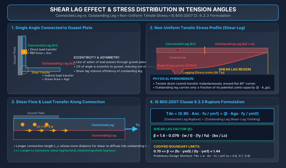
Key Architectural Insights from Figure 1:
- Decoupled Capacity Model: The IS 800:2007 formulation separates the angle into two distinct behavioral zones: the connected leg which fails by net section rupture (), and the outstanding leg which fails by shear-lagged yielding ().
- Stress Gradient: Due to shear lag, tensile stress decays from a maximum peak at the fastener line to a minimum at the free outstand tip.
- Connection Diffusivity: Longer connection lengths allow more shear flow across the heel junction, raising the shear lag factor closer to its theoretical ceiling of .
Figure 2: Shear Lag Width () & Connection Length () Geometry
+----------------------------------------------------------------------------------------------------+
|                                  SHEAR LAG GEOMETRIC PARAMETERS                                    |
|                                                                                                    |
|    [BOLTED ANGLE: bs = w + w1 - t]                   [WELDED ANGLE: bs = w]                        |
|                                                                                                    |
|       Gusset       Connected Leg (b1)                   Gusset       Connected Leg (b1)            |
|         ||   +-------------------+                        ||   +-------------------+               |
|         ||   |     (o) Bolt Line |                        ||   |      Toe Weld ===>|               |
|         ||   |        |          |                        ||   |                   |               |
|         ||   |        |<-- w1 -->| Heel                   ||   |                   | Heel          |
|         ||   +--------+----------+                        ||   +-------------------+               |
|         ||            |          |                             |                   |               |
|                       |<------- w ------->|                                        |<------ w ---->|
|                       |<------ bs ------->|                                        |<- bs = w ---->|
|                                                                                                    |
|    [CONNECTION LENGTH Lc]: Bolted: Lc = (n-1)*p   |   Welded: Lc = Lw (Longer weld)                |
+----------------------------------------------------------------------------------------------------+
The precise geometric definitions of and are illustrated below:
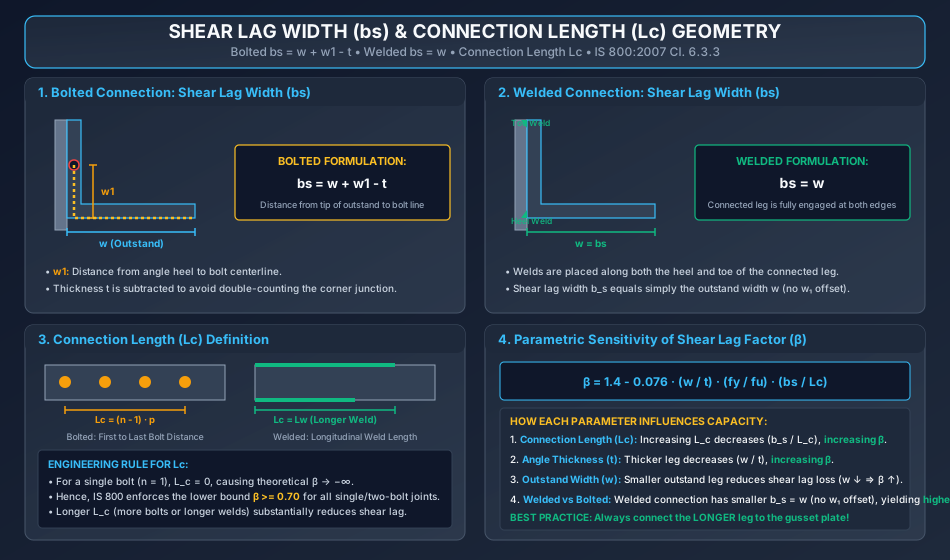
Key Architectural Insights from Figure 2:
- Unfolded Width (): For bolted joints, traces the total distance from the outstand tip around the corner to the fastener centerline, deducting to avoid double-counting.
- Welded Superiority (): In welded joints, dual weld lines along the heel and toe eliminate the offset, reducing to . This increases and provides higher rupture resistance.
- Single Bolt Vulnerability: If only one bolt is provided (), , causing severe shear lag; the code restricts to its lower bound of .
7. Step-by-Step Design Procedures & Workflows
7.1 Workflow: Evaluation of Angle Tension Member Capacity
[START: Given Angle Section b1 x b2 x t, Connection Type (Bolted/Welded)]
       |
       v
[Step 1: Compute Component Areas]
       --> For Bolted: Anc = (b1 - d0 - t/2) * t
       --> For Welded: Anc = (b1 - t/2) * t
       --> Outstanding Leg: Ago = (b2 - t/2) * t
       --> Gross Area: Ag = (b1 + b2 - t) * t
       |
       v
[Step 2: Determine Shear Lag Geometric Parameters]
       --> Outstand width w = b2
       --> For Bolted: bs = w + w1 - t; Lc = (n - 1) * p
       --> For Welded: bs = w; Lc = length of longer weld
       |
       v
[Step 3: Calculate Shear Lag Factor (β)]
       --> beta_calc = 1.4 - 0.076 * (w / t) * (fy / fu) * (bs / Lc)
       --> Check limits: beta = max(0.70, min(beta_calc, 1.4432))
       |
       v
[Step 4: Compute Design Capacities per IS 800:2007]
       --> Gross Yielding: Tdg = (Ag * fy) / gamma_m0
       --> Net Rupture: Tdn = (0.90 * Anc * fu / gamma_m1) + (beta * Ago * fy / gamma_m0)
       --> Block Shear: Tdb = min(Tdb1, Tdb2)  (refer to STEEL-02-03)
       |
       v
[Step 5: Determine Governing Design Tensile Strength]
       --> Td = min(Tdg, Tdn, Tdb)
       --> Compare with Factored Tensile Load Tu: Is Td >= Tu?
           |-- NO  --> Choose larger angle section or increase Lc.
           |-- YES --> SAFE. Proceed to slenderness check. [END]
8. Solved Numerical Examples (Pre-Calculated & Multi-Step)
Problem 1: Bolted Single Angle Tension Member (ISA )
Statement: A single unequal angle tension member ISA of Fe 410 steel () is connected by its longer leg () to a thick gusset plate using 4 bolts of M20 Class 4.6 () arranged in a single line. The bolt pitch is , and the gauge distance from the heel of the angle is . Calculate:
- The shear lag factor .
- The design net rupture strength .
- The design gross section yielding strength .
- The governing design tensile strength .
       Gusset Plate (t = 10 mm)
          | |
          | |   ISA 90 x 60 x 8 mm
          | |==================================> Tu (Tension Load)
          | |     o     o     o     o
          | |    p=60  p=60  p=60
          | |<---------- Lc = 180 mm --------->
Step 1: Cross-Sectional Areas
- Thickness .
- Connected leg width , hole diameter :
- Outstanding leg width :
- Gross area:
Step 2: Shear Lag Parameters ()
- Outstanding width: .
- Gauge from heel: .
- Shear lag width for bolted joint:
- Length of connection ( at ):
Step 3: Calculation of Shear Lag Factor () Per IS 800:2007 Cl. 6.3.3:
Substitute the numeric values:
Check code limits:
- Lower limit: .
- Upper limit:
Since , adopt:
Step 4: Design Rupture Strength ()
- Connected leg contribution:
- Outstanding leg contribution:
- Total rupture capacity:
Step 5: Design Gross Section Yielding Strength ()
Step 6: Governing Design Tensile Strength ()
Conclusion: The single angle tension member has a design tensile capacity of , governed by gross section yielding.
Problem 2: Welded Single Angle Tension Member Comparison
Statement: The same unequal angle ISA (Fe 410) from Problem 1 is connected to the gusset plate using longitudinal fillet welds instead of bolts. The weld along the heel has length , and the weld along the toe has length . Calculate the design rupture strength and compare it with the bolted joint capacity.
Step 1: Cross-Sectional Areas for Welded Joint Since there are no bolt holes in the connected leg:
- Connected leg:
- Outstanding leg:
- Gross area:
Step 2: Shear Lag Parameters for Welded Joint
- For welded connection:
- Connection length:
Step 3: Shear Lag Factor ()
Check limits: .
Step 4: Design Rupture Strength ()
- Connected leg:
- Outstanding leg:
- Total rupture strength:
Step 5: Comparative Analysis
- Bolted joint rupture capacity: .
- Welded joint rupture capacity: .
- Percentage gain:
Conclusion: Welded connections eliminate bolt hole deductions and reduce shear lag width (), increasing net rupture capacity by .
Problem 3: Double Angles Back-to-Back — Tack Bolting & Design
Statement: A tension tie in a bridge truss consists of two unequal angles 2 ISA (Fe 410) connected back-to-back on opposite sides of a gusset plate. The member is subjected to a factored axial tensile force . The longer legs () are connected to the gusset plate using 4 M20 bolts () per angle at pitch (), with gauge from heel .
- Verify the adequacy of the double angle member against gross yielding and net rupture.
- Determine the maximum permissible spacing of intermediate tack bolts per IS 800:2007 Cl. 10.2.5.5 for a total clear member span of .
Step 1: Section Properties for One Angle
- Connected leg , outstand , thickness .
- .
- .
- .
Step 2: Shear Lag Factor () per Angle
- Outstand .
- Gauge .
- Shear lag width:
- Connection length:
- Calculate :
Check limits: .
Step 3: Rupture Strength for One Angle ()
Step 4: Total Capacity of Double Angle Member (2 Angles)
- Total Net Rupture Strength:
- Total Gross Section Yielding Strength:
- Controlling Design Strength:
Check adequacy:
Step 5: Tack Bolting Requirements per IS 800:2007 Cl. 10.2.5.5
- For double angle members subjected to axial tension, the pitch of tacking bolts shall not exceed .
- For total member length :
- Specification: Provide intermediate tack bolts with pack washers at centers (2 intermediate tack bolts along the span).
9. Common Pitfalls, Edge Cases & Failure Modes
- Forgetting Deduction in and :
- Pitfall: Computing and .
- Consequence: Double-counting the corner square of area , overestimating cross-sectional area and design capacity.
- Applying Bolted Equation to Welded Connections:
- Pitfall: Using for welded angles.
- Correction: In welded angles, is not applicable because weld lines clamp both the heel and toe; strictly use .
- Single Bolt Connection Shear Lag Limitation:
- Pitfall: Attempting to evaluate for a 1-bolt connection (), resulting in mathematical division by zero.
- Rule: For single-bolt joints, the code enforces (or using the preliminary formula).
- Connecting the Shorter Leg to the Gusset Plate:
- Pitfall: Connecting the shorter leg () while leaving the longer leg () outstanding.
- Consequence: Outstand width increases by , sharply depressing the shear lag factor and losing up to of member capacity. Always connect the longer leg.
- Omitting Tack Fasteners in Double Angle Members:
- Pitfall: Assuming two angles placed back-to-back act together without intermediate tack bolts.
- Consequence: Without tacking at , each angle vibrates independently, experiences transverse buckling under accidental compression, and violates IS 800 Cl. 10.2.5.5.
10. Exam-Specific Focus Points & Rapid Revision Notes
10.1 Quick Revision Formula Card
- Rupture Formula:
- Shear Lag Factor:
- Bounds on :
- Bolted Shear Lag Width:
- Welded Shear Lag Width:
- Connection Length: (Bolted) or (Welded).
- Preliminary Shortcut: ( for 1-2 bolts, 3 bolts, bolts).
- Max Tack Bolt Spacing: (Tension) / (Compression).
10.2 Examination Nuances
- GATE CE: Often asks to calculate the exact numerical value of for a given bolted or welded angle, testing whether the candidate remembers the lower bound or correctly sets for welds.
- ESE Prelims: Frequently tests the partial safety factors (), the definition of , and the preliminary values of ().
- SSC JE & State AE/JE: Direct factual questions on maximum tack bolt spacing ( for tension ties) and the reason why the longer leg of an unequal angle is connected to the gusset.
11. Practice Problems & Self-Assessment Question Bank
- Question 1 (Conceptual): Why is the shear lag factor multiplied by the yield stress and divided by , while the connected leg area is multiplied by ultimate tensile strength and divided by ?
- Answer: The connected leg undergoes severe localized plastic strain at the bolt holes and fails by ultimate tensile rupture (). The outstanding leg is restrained from immediate fracture by the shear lag gradient; its stress is limited to an effective yield contribution () at the instant the connected leg ruptures.
- Question 2 (Formula Application): For an ISA angle (Fe 410) connected by its leg with welds (), calculate and determine .
- Answer: For welded connection: . . . . . Since , .
- Question 3 (GATE Numeric): An angle tension member has and (Fe 410 steel). If , compute the design net rupture strength .
- Answer: .
- Question 4 (Preliminary Design Shortcut): Estimate the net rupture capacity of an angle with total net area (Fe 410) connected by 3 bolts using the simplified preliminary equation of IS 800 Cl. 6.3.3.
- Answer: For 3 bolts, . .
- Question 5 (Tack Bolting): What is the primary structural consequence if tack bolts are omitted along the span of a double-angle tension tie?
- Answer: Without tack bolts, the two angles act as independent slender elements rather than a combined symmetric section. Any accidental compressive rebound, wind flutter, or seismic load will induce premature buckling in the individual angles at a slenderness ratio governed by their individual .
12. Bibliographic References & Standard Codes
- Bureau of Indian Standards: IS 800:2007 — General Construction in Steel — Code of Practice (Third Revision), BIS, New Delhi.
- Subramanian, N.: Design of Steel Structures (Limit State Method), Oxford University Press, 2018.
- Duggal, S. K.: Limit State Design of Steel Structures, McGraw Hill Education (India), 2nd Edition, 2019.
- Bhavikatti, S. S.: Design of Steel Structures By Limit State Method as per IS: 800-2007, I.K. International Publishing House.
- INSDAG: Design of Tension Members, Institute for Steel Development & Growth, Kolkata.
- AISC 360-16: Specification for Structural Steel Buildings, American Institute of Steel Construction, Chicago.