Prying Action & High-Strength Fastener Mechanics (IS 800:2007 & IS 4000:1992)
In this chapter (4 topics)
On this page
- 1. Topic Overview & Engineering Context
- 2. Governing Codes, Standards & Design Philosophy
- 3. Kinematics, Mechanics & Fundamental Principles
- 3.1 Kinematics of Prying Action in a T-Stub Connection
- 3.2 Failure Modes of Flange-Fastener Sub-assemblies
- 4. Mathematical Formulations & Derivations
- 4.1 Derivation of IS 800:2007 Prying Force Formulation
- 4.2 Definition of Geometric Lever Arms
- 4.3 Critical Flange Thickness to Eliminate Prying (tcrit)
- 5. IS 800:2007 Design Specifications & Detailing Rules
- Table 1: Prying Force Parameters and Factors (IS 800:2007 Cl. 10.4.7)
- 6. Engineering Diagrams & Visual Explanations
- Figure 1: Prying Action Mechanics & Lever Arm Geometry
- Figure 2: High-Strength Fastener Mechanics & Tightening Methods
- 7. Step-by-Step Design Procedures & Workflows
- 7.1 Workflow: Assessment and Design of Prying-Prone Connections
- 8. Solved Numerical Examples (Pre-Calculated & Multi-Step)
- Problem 1: Evaluation of Prying Force in a Bolted T-Stub Connection
- Problem 2: Determination of Flange Thickness to Eliminate Prying Action
- Problem 3: HSFG Connection under Combined Shear and Tension with Tightening Verification
- 9. Common Pitfalls, Edge Cases & Failure Modes
- 10. Exam-Specific Focus Points & Rapid Revision Notes
- 10.1 Quick Revision Formula Card
- 10.2 Examination Nuances
- 11. Practice Problems & Self-Assessment Question Bank
- 12. Bibliographic References & Standard Codes
1. Topic Overview & Engineering Context
In structural steel moment connections, beam-to-column tension flange splices, hanger connections, and T-stub base details, fasteners are subjected to direct axial tension. When the connecting components (flanges, end plates, or cleat angles) have finite flexural flexibility, external tensile forces induce out-of-plane bending distortion in the plate elements. As the plate deforms, its outer edges or tips press tightly against the supporting base or opposing flange, creating reactive contact forces. This phenomenon is known as prying action, and the resulting reactive contact force is designated as the prying force ().
Prying action modifies the internal equilibrium of the joint:
- It introduces an internal lever mechanism that increases the total tensile demand on the fasteners from the applied external tension () to a higher resultant tension:
- In flexible connections, the prying force can magnify bolt tension by to over , precipitating sudden tensile rupture or fatigue unseating of fasteners at loads significantly below design calculations that ignore prying.
- Proper understanding of prying mechanics allows structural engineers either to accurately size fasteners to accommodate , or to configure flange thickness and stiffener geometry such that prying action is completely suppressed ().
Simultaneously, the reliable structural performance of modern high-strength friction grip (HSFG) connections hinges upon achieving and verifying the design clamping proof load (). Standardized tightening technologies—such as the Turn-of-Nut method, calibrated torque wrenches, direct tension indicator (DTI) washers, and tension-control (TC) twist-off bolts—provide the necessary mechanical and quality-assurance controls mandated by IS 800:2007 and IS 4000:1992.
                   +-------------------------------------------------------------+
                   |         AXIAL TENSION IN STRUCTURAL BOLTED JOINTS           |
                   +-------------------------------------------------------------+
                                                 |
                   +-----------------------------+-----------------------------+
                   |                                                           |
                   v                                                           v
       [THICK / RIGID FLANGE]                                      [THIN / FLEXIBLE FLANGE]
       * Flange thickness t >= t_crit                              * Flange thickness t < t_crit
       * No tip contact with base                                  * Flange tips bend and press base
       * Prying Force Q = 0                                        * Prying Force Q > 0 develops
       * Fastener Tension: Tb = Te                                 * Fastener Tension: Tb = Te + Q
       * Pure bolt tension failure                                 * Combined tension + prying bending
2. Governing Codes, Standards & Design Philosophy
The analysis and mitigation of prying action, alongside high-strength fastener installation, is governed by national and international structural standards:
- IS 800:2007 (Code of Practice for General Construction in Steel):
- Clause 10.4.7 (Prying Forces): Formulates the prying force in bolts subjected to tensile loads as a function of flange flexural stiffness, lever arms and , fastener preload factor , and bolt proof stress :
- Clause 10.4.5 & 10.4.6: Tensile capacity of HSFG bolts () and linear interaction under simultaneous shear and tension:
- Clause 10.4.3: Reduction in slip resistance under applied external tension:
- IS 4000:1992 (Code of Practice for High Strength Bolts in Steel Structures):
- Specifies fabrication tolerances, tightening methods (Turn-of-Nut, calibrated wrench, torque measurement), and site verification testing.
- AISC 360-16 & Eurocode 3 (EN 1993-1-8):
- Formulates T-stub equivalent models with three distinct failure modes: Mode 1 (complete flange yielding with 4 plastic hinges), Mode 2 (bolt failure with flange yielding and 2 plastic hinges), and Mode 3 (pure bolt tensile rupture with thick rigid flange and zero prying).
3. Kinematics, Mechanics & Fundamental Principles
3.1 Kinematics of Prying Action in a T-Stub Connection
Consider an inverted T-stub subjected to an upward tension force , connected to a rigid base by two symmetrical rows of fasteners:
- Un-deformed Initial State: The fasteners clamp the T-stub flange against the rigid base with proof preload . The contact pressure between the plies is initially concentrated beneath the bolt heads and surrounding washer contact zones.
- Deformation under Tensile Load: When external tension is applied through the web plate:
- The flange plate acts as a cantilever beam extending outward from the web fillet toe.
- Bending moments develop across the flange plate, causing it to curvature upward.
- The region of the flange under the bolt head undergoes tensile stretching along the bolt axis.
- Contact Transfer to the Flange Tips:
- Because the outer edges of the flange cannot penetrate the rigid base, the bending deformation forces the extreme tips of the flange against the base surface.
- A reactive compressive contact force is mobilized at the flange tip.
- Internal Equilibrium of the Flange Cantilever:
- Taking vertical equilibrium of one half of the T-stub:
- Taking moment equilibrium about the bolt centerline: where is the lever arm from the bolt centerline to the line of action of the prying force .
- Taking moment equilibrium about the web root/fillet: where is the distance from the bolt centerline to the toe of the fillet weld or root of the flange.
       2 Te (External Factored Tension)
          |
          v
       +--+--+
       | Web |
       +--+--+
      /       \
  ===+=========+===   <- Fillet toe (Root)
  |   |   |   |   |
  |   |   |   |   |   <- Flange plate (thickness t)
  +---+---+---+---+
    |   o   |   o   |
    |   |   |   |   |
   [Q] [Tb]   [Tb] [Q] <- Reactive prying forces Q at outer tips
   ================== <- Rigid Base Element
      |<-lv->|<-le->|
3.2 Failure Modes of Flange-Fastener Sub-assemblies
As external tension increases to failure, the sub-assembly undergoes one of three structural mechanisms:
- Mode 1 (Thin Flange Mechanism): Extensive plastic bending occurs in the flange. Plastic hinges form both at the bolt centerline and at the web root before bolt fracture. High prying forces () develop. Failure is ductile flange flexural yielding.
- Mode 2 (Intermediate Flange Mechanism): A single plastic hinge forms at the web root while the bolt reaches its ultimate tensile strength under combined tension (). Failure is simultaneous flange yielding and bolt tensile fracture.
- Mode 3 (Thick Flange Mechanism): The flange is sufficiently thick () such that its flexural deflection is negligible. Flange tips never contact the base (). Failure is pure bolt tensile rupture governed strictly by .
4. Mathematical Formulations & Derivations
4.1 Derivation of IS 800:2007 Prying Force Formulation
The prying formulation in IS 800:2007 Cl. 10.4.7 is derived from elastic-plastic plate bending theory combined with compatibility of axial bolt elongation and plate tip deflection:
- Deflection Compatibility: Let be the axial elongation of the bolt under tension : Let be the downward flexural deflection of the flange cantilever tip relative to the bolt line. If the flange tip touches the rigid base, the net displacement at the tip must equal zero:
- Moment and Plastic Resistance: The ultimate plastic moment capacity of the effective flange width of thickness is: In limit state analysis, incorporating non-linear strain hardening, fastener pre-load stiffening (), and empirical factor : The resistance of the plate to tip contact leads to the subtrahend term:
- Resultant Prying Force:
Equating moments about the bolt center and incorporating the lever arm ratio :
- If , then , which physically means the flange is too stiff to allow tip contact; is taken as 0.
4.2 Definition of Geometric Lever Arms
- (Inner Lever Arm): Distance from the bolt centerline to the toe of the fillet weld or root radius of the rolled section: where is distance from web center to bolt line, is root radius, and is weld leg size.
- (Outer Lever Arm): Distance from the bolt centerline to the edge of the flange, subject to a codified upper bound: Engineering Rationale for the Limit: If the physical edge distance is very large, the flange tip bends into an S-curve and lifts off before the actual edge, shifting the contact line inward to an effective distance .
4.3 Critical Flange Thickness to Eliminate Prying ()
Setting in the prying equation:
Substituting the upper-bound relationship :
Solving for :
5. IS 800:2007 Design Specifications & Detailing Rules
Table 1: Prying Force Parameters and Factors (IS 800:2007 Cl. 10.4.7)
| Parameter | Symbol | Value for Non-Preloaded Bolts (Class 4.6) | Value for Preloaded HSFG Bolts (Class 8.8 / 10.9) |
|---|---|---|---|
| Preload Factor | |||
| Empirical Factor | |||
| Proof Stress | Yield stress (e.g. ) | Proof stress (e.g. for 8.8, for 10.9) | |
| Effective Width | Tributary flange width per bolt | Tributary flange width per bolt | |
| Upper Bound on | |||
| Tensile Capacity | / | ||
| Safety Criterion | — |
6. Engineering Diagrams & Visual Explanations
Figure 1: Prying Action Mechanics & Lever Arm Geometry
+----------------------------------------------------------------------------------------------------+
|                                PRYING ACTION KINEMATICS & LEVER ARMS                               |
|                                                                                                    |
|    Web Plate                Flange Plate (Flexible, thickness t)                                   |
|    +-------+         +-------------------------------+                                             |
|    |       |         |                                \                                            |
|    |   |   |   Root  |           Bolt Line             \                                           |
|    |   v   |  Fillet |               |                  \                                          |
|    |  2 Te |====x====+===============o===================x Contact Line                            |
|    |       |    |                    |                   |                                         |
|    +-------+    |<------- lv ------->|<------- le ------>|                                         |
|                 |                    |                   |                                         |
|   =================================================================== Rigid Base                   |
|                                      ^                   ^                                         |
|                                      |                   |                                         |
|                            Bolt Tension Tb = Te + Q     Prying Force Q                             |
+----------------------------------------------------------------------------------------------------+
The kinematic deformation, lever arm geometry, and IS 800:2007 formulation are illustrated below:
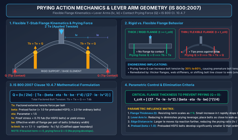
Key Architectural Insights from Figure 1:
- Kinematic Lever Action: The flange plate pivots over the rigid base. Outer tip contact acts as a fulcrum, transforming the bolt into an interior reaction point carrying both external load and fulcrum reaction .
- Flange Thickness Scaling (): The flexural resistance term in the prying formula scales with the fourth power of thickness (). Consequently, a modest increase in flange thickness produces an enormous reduction in prying force.
- Preload Stiffening (): Preloaded HSFG bolts () experience substantially lower prying forces than ordinary bolts () because the initial clamping force resists separation up to the decompression threshold.
Figure 2: High-Strength Fastener Mechanics & Tightening Methods
+----------------------------------------------------------------------------------------------------+
|                                HSFG BOLT TIGHTENING TECHNOLOGIES                                   |
|                                                                                                    |
|    [Turn-of-Nut Method]       [Calibrated Torque Wrench]      [Direct Tension Indicators]          |
|    * Snug-tight base          * Daily Skidmore calibration    * Calibrated arch protrusions        |
|    * 1/3 to 2/3 nut turn      * T = K * d * Fo                * Feeler gauge gap <= 0.125 mm       |
|    * Match-mark visual QA     * Hardened washer under turn    * Silicone squirter visual QA        |
|                                                                                                    |
|    [Twist-Off TC Bolts]                                                                            |
|    * Electric shear wrench with dual counter-rotating sockets                                      |
|    * Inner socket holds splined stem; outer socket tightens nut                                    |
|    * Spline twists off automatically at proof load Fo; 100% fail-safe inspection                   |
+----------------------------------------------------------------------------------------------------+
The four standardized tightening and quality assurance methods are illustrated below:
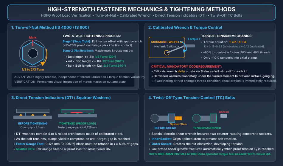
Key Architectural Insights from Figure 2:
- Turn-of-Nut Independence: The Turn-of-Nut method is insensitive to thread lubrication and rust variations because it directly controls strain (elongation) rather than friction-dependent torque.
- Torque-Tension Friction Loss: In torque-controlled tightening (), approximately of applied torque is consumed overcoming thread and nut-face friction; only generates axial clamping tension.
- Fail-Safe TC Fasteners: Twist-off tension-control bolts eliminate operator error entirely; the spline fracture physically guarantees that the designed proof preload has been attained.
7. Step-by-Step Design Procedures & Workflows
7.1 Workflow: Assessment and Design of Prying-Prone Connections
[START: Given Factored External Tension 2*Te, Flange Width, Geometry]
       |
       v
[Step 1: Determine External Tension per Fastener (Te)]
       --> Te = Total Factored Tension / Total Number of Fasteners
       |
       v
[Step 2: Identify Geometric Lever Arms (lv, le)]
       --> lv = Distance from bolt centerline to root of web / fillet toe
       --> Physical edge distance e
       --> Compute codified limit: le_max = 1.1 * t * sqrt(beta * fo / fy)
       --> Adopted le = min(e, le_max)
       |
       v
[Step 3: Select Fastener Material & Preload Parameters]
       --> For Class 8.8 HSFG: fub = 800 MPa, fo = 0.70 fub = 560 MPa, beta = 1.0
       --> For Class 4.6 Bearing: fub = 400 MPa, fo = fyb = 240 MPa, beta = 2.0
       --> Set eta = 1.5, determine tributary width be
       |
       v
[Step 4: Compute Subtrahend & Check Prying Existence]
       --> Subtrahend = (beta * eta * fo * be * t^4) / (27 * le * lv^2)
       --> Is Te > Subtrahend?
           |-- NO  --> Flange is rigid: Q = 0, Tb = Te. (Skip to Step 6)
           |-- YES --> Flange is flexible: Compute Q = (lv / 2le) * [Te - Subtrahend]
       |
       v
[Step 5: Compute Total Bolt Tensile Demand]
       --> Tb = Te + Q
       |
       v
[Step 6: Capacity Verification per IS 800:2007]
       --> Tdf = (0.90 * fub * Anb) / gamma_mf
       --> Is Tb <= Tdf?
           |-- NO  --> UNSAFE: Increase bolt diameter, increase flange thickness t,
           |           or add stiffeners. Repeat from Step 1.
           |-- YES --> SAFE. Proceed to combined interaction / shear checks. [END]
8. Solved Numerical Examples (Pre-Calculated & Multi-Step)
Problem 1: Evaluation of Prying Force in a Bolted T-Stub Connection
Statement: A T-stub tension hanger fabricated from Fe 410 steel () carries a total factored tensile load of . The connection to a rigid base is made using two M20 Class 8.8 HSFG preloaded bolts (). The flange plate has thickness and tributary width per bolt . The inner distance from bolt line to weld toe is , and the physical edge distance is . Calculate the prying force , the total tensile demand , and verify the adequacy of the bolts per IS 800:2007 Cl. 10.4.7.
Step 1: Factored Tension per Bolt ()
Step 2: Bolt Material and Preload Parameters
- Grade 8.8 HSFG bolt:
- Preloaded HSFG bolt:
- Empirical parameter:
- Steel plate yield strength:
Step 3: Effective Lever Arm () Check the codified upper bound for per IS 800:2007 Cl. 10.4.7:
Since the physical edge distance :
Step 4: Calculation of Prying Force () Substitute into IS 800:2007 Cl. 10.4.7:
- Numerator of subtrahend:
- Denominator of subtrahend:
- Value of subtrahend:
- Bracket term:
- Multiplier ratio:
- Prying force:
Step 5: Total Bolt Tensile Force ()
(Notice that prying action increases the bolt tension by !)
Step 6: Tensile Capacity Check per IS 800:2007 Cl. 10.4.5
Check:
Conclusion: The bolts are SAFE against tensile failure including prying action.
Problem 2: Determination of Flange Thickness to Eliminate Prying Action
Statement: For the T-stub connection in Problem 1 (), determine the minimum flange thickness required so that prying action is completely eliminated (). Check the connection with a practical plate thickness of .
Step 1: Governing Condition for Zero Prying () Prying force vanishes () when the subtrahend equals or exceeds the external tension:
Expressing in terms of :
Substituting into the inequality:
Solving for :
Step 2: Numeric Evaluation
Step 3: Verification with Practical Plate Thickness () Adopt standard commercially available plate thickness: .
- Calculate : Since physical edge distance , .
- Calculate Subtrahend with and :
- Since :
Conclusion: Providing a flange plate completely eliminates prying action (), reducing bolt tensile stress by and improving fatigue life.
Problem 3: HSFG Connection under Combined Shear and Tension with Tightening Verification
Statement: A beam-to-column splice connection carries a factored shear force and a factored axial tension . The connection uses 4 M20 Class 8.8 HSFG bolts in single shear () with standard clearance holes (). The slip coefficient is , and the safety factor for slip at ultimate limit state is .
- Compute the clamping proof load .
- Determine the reduced slip resistance of the joint under external tension per IS 800:2007 Cl. 10.4.3.
- Verify the joint against the linear interaction formula of IS 800:2007 Cl. 10.4.6.
- Specify the required tightening procedure using the Turn-of-Nut method for bolt length .
Step 1: Factored Actions per Fastener
- Factored shear per bolt:
- Factored tension per bolt:
Step 2: Clamping Proof Load () Per IS 800:2007 Cl. 10.4.3.2:
Step 3: Basic Slip Resistance () without Tension
Step 4: Reduced Slip Resistance () under Simultaneous Tension Per IS 800:2007 Cl. 10.4.3: External tension reduces the effective clamping force:
Reduced design slip resistance:
Direct check:
Step 5: Linear Interaction Check per IS 800:2007 Cl. 10.4.6
- Design tension capacity of M20 Class 8.8 HSFG bolt:
- Evaluate the linear interaction criterion using basic unreduced slip capacity :
Since , the connection is SAFE under combined shear and tension with structural reserve.
Step 6: Tightening Specification (Turn-of-Nut Method)
- Bolt nominal diameter , length .
- Ratio .
- Per IS 4000:1992 Table 3, for :
- Bring connection plies into firm contact to achieve Snug-Tight condition using full manual effort of a worker with an ordinary spud wrench.
- Apply permanent match marks across the protruding bolt end and nut face using paint or a center punch.
- Rotate the nut through relative to the bolt shank using an impact or manual torque multiplier wrench.
9. Common Pitfalls, Edge Cases & Failure Modes
- Omitting Prying Force in Hanger / Flange Connection Sizing:
- Pitfall: Calculating bolt tension strictly as without verifying flange flexibility.
- Consequence: Underestimating bolt tension by up to , causing brittle tensile fracture of fasteners under design loads.
- Exceeding the Upper Bound on Lever Arm :
- Pitfall: Using the physical edge distance in the prying equation when .
- Correction: The contact line of prying shifts inward due to reverse curvature. Always enforce .
- Assuming Preloaded HSFG Bolts Eliminate Prying Action:
- Misconception: Believing that because HSFG bolts are preloaded, prying cannot occur.
- Reality: Preload delays the onset of separation, but once external tension relieves decompression, flexible flanges will pry. HSFG bolts merely have (reducing ), but is not zero unless .
- Calibrated Wrench Miscalibration & Weathering:
- Pitfall: Relying on torque wrench settings without daily site calibration using a Skidmore-Wilhelm tension calibrator.
- Consequence: Minor surface rust, dust, or lack of lubricant on threads can increase the torque coefficient from to over . An operator applying the specified torque may only develop of the required proof load , leading to premature slip failure.
- Re-using HSFG Bolts:
- Rule: Once an HSFG bolt has been fully tightened to its proof load into the plastic elongation regime, it must never be re-used if loosened or dismantled.
10. Exam-Specific Focus Points & Rapid Revision Notes
10.1 Quick Revision Formula Card
- Prying Force:
- Preload Factors: (Preloaded HSFG), (Non-preloaded bearing bolts); .
- Proof Stress: (HSFG) or (Bearing).
- Upper Bound on : .
- Zero Prying Threshold: .
- Total Bolt Tension: .
- Reduced Slip under Tension: .
- HSFG Linear Interaction: .
- Turn-of-Nut Rotations:
10.2 Examination Nuances
- GATE CE: Numerical questions focus on computing the reduction in slip capacity due to external tension () and the linear interaction formula.
- ESE Prelims: Frequently tests the definition of lever arms and , the scaling of flange resistance, and the values of ( vs ).
- SSC JE & State AE/JE: Direct objective questions on Turn-of-Nut rotation fractions ( turn) and the torque-tension equation .
11. Practice Problems & Self-Assessment Question Bank
- Question 1 (Conceptual): Why does an increase in the flange thickness have an exceptionally strong effect in reducing the prying force ?
- Answer: In the IS 800:2007 prying formulation, the flexural resistance term subtracted from external tension scales with the fourth power of thickness (), representing plate flexural rigidity ( combined with lever arm mechanics). Doubling increases this resistance by times, rapidly driving to zero.
- Question 2 (Formula Application): An M22 Class 8.8 HSFG bolt () carries an external factored tension . If the prying force is calculated as , determine total bolt tension and check safety ().
- Answer: . Design tension capacity . Since , the bolt is safe (59% utilization).
- Question 3 (GATE Numeric): An HSFG bolted joint has a basic design slip resistance per bolt under pure shear. If each bolt is simultaneously subjected to an external factored tension , what is the reduced design slip resistance ? (Take initial proof load ).
- Answer: Clamping force reduces by . Net clamping force . Reduced slip capacity .
- Question 4 (Tightening Mechanics): In the Turn-of-Nut method, what is the purpose of the "Snug-Tight" stage before the nut is rotated by the specified fraction of a turn?
- Answer: The snug-tight stage brings all connecting plies into uniform, firm contact across the entire faying surface, eliminating initial gaps, warpage, and slack. This establishes a true zero-datum so that subsequent nut rotation produces predictable elastic-plastic strain in the bolt shank.
- Question 5 (Turn-of-Nut Rules): A structural bolt has nominal diameter and total length . What fraction of nut rotation is required after snug tightening?
- Answer: . Since , the required nut rotation is .
12. Bibliographic References & Standard Codes
- Bureau of Indian Standards: IS 800:2007 — General Construction in Steel — Code of Practice (Third Revision), BIS, New Delhi.
- Bureau of Indian Standards: IS 4000:1992 — High Strength Bolts in Steel Structures — Code of Practice (First Revision), BIS, New Delhi.
- Kulak, G. L., Fisher, J. W., & Struik, J. H. A.: Guide to Design Criteria for Bolted and Riveted Joints, 2nd Edition, American Institute of Steel Construction (AISC), Chicago.
- Subramanian, N.: Design of Steel Structures (Limit State Method), Oxford University Press, 2018.
- Duggal, S. K.: Limit State Design of Steel Structures, McGraw Hill Education (India), 2nd Edition, 2019.
- INSDAG: Design Guide for Bolted Connections, Institute for Steel Development & Growth, Kolkata.