Post-Buckling Shear Mechanics & Tension Field Action (IS 800:2007 Cl. 8.4.2.2 b)
In this chapter (4 topics)
On this page
- 1. Executive Summary & Code Hierarchy
- 2. Elastic Plate Buckling Mechanics & Shear Coefficient kv
- 2.1 The Bryan-Timoshenko Plate Equation
- 2.2 Shear Buckling Coefficient kv (IS 800:2007 Cl. 8.4.2.2)
- 3. Basler vs Rockey-Cardiff Post-Buckling Models
- 3.1 Basler's Tension Field Theory (1961)
- 3.2 The Rockey-Cardiff Kinematic 4-Hinge Model (IS 800 Foundation)
- 4. IS 800:2007 Tension Field Formulation (Cl. 8.4.2.2 b)
- 4.1 Step 1: Pre-Buckling Shear Stress τb
- 4.2 Step 2: Tension Field Inclination Angle φ
- 4.3 Step 3: Diagonal Membrane Tension Stress fv
- 4.4 Step 4: Flange Anchorage Distance s & Tension Field Width wtf
- 4.5 Step 5: Post-Buckling Shear Resistance Vt
- 5. Boundary Anchoring Mechanics: Rigid vs Non-Rigid End Posts
- 5.1 Interior Panels
- 5.2 End Panels: The Rigid End Post Requirement (Cl. 8.5.3)
- 6. Interaction Between Shear and Bending in Stiffened Webs
- 7. SVG Engineering Visualizations
- FIGURE STEEL-05-02A: Tension Field Action Mechanics & Pratt Truss Analogy
- FIGURE STEEL-05-02B: Mohr's Circle Yield Criterion & Cardiff 4-Hinge Mechanism
- 8. Complete Step-by-Step Mathematical Derivations
- Derivation 1: Von Mises Yield Criterion for Membrane Tension Field Stress fv
- Derivation 2: Flange Plastic Mechanism & Anchorage Length s (Cardiff Model)
- 9. Multi-Exam Comprehensive Solved Examples
- Example 1: Full Tension Field Action Capacity (GATE CE / ESE Conventional)
- Example 2: Effect of Transverse Stiffener Spacing (c/d Ratio)
- Example 3: End Panel Anchoring & Rigid End Post Design
- 10. Exam Traps, Common Pitfalls & Field Failure Modes
- Trap 1: Assuming Tension Field Action Always Exists
- Trap 2: Stiffener Spacing Aspect Ratio c/d Formula Inversion
- Trap 3: Confusion Between Vn and Vd
- Trap 4: Neglecting the Flange Thickness Influence
- 11. Comparative Synthesis & Summary Matrix
- 12. Official Exam Practice Questions
- Question 1 (GATE CE)
- Question 2 (UPSC ESE)
- Question 3 (SSC JE)
- Question 4 (State AE / RRB JE)
- Question 5 (UPSC ESE Conventional)
1. Executive Summary & Code Hierarchy
In conventional beam design (such as rolled I-sections where ), the ultimate shear capacity is governed by full plastic shear yielding across the web (). However, in deep plate girders spanning long distances ( in railway and highway bridges, industrial cranes, and large-span transfer girders), dead load economy requires very thin web plates (). Under such extreme slenderness, the web plate buckles elastically at a nominal shear stress far below the shear yield strength (for E250 steel).
Historically, early elastic design codes (e.g., pre-1984 standards) treated elastic shear buckling as the ultimate failure limit. Extensive experimental research conducted by Basler (Lehigh University, 1961) and later refined by Rockey, Evans, and Porter (Cardiff University, 1970s–1980s) revealed that shear buckling does not precipitate collapse. Instead, the buckled web undergoes a fundamental structural metamorphosis:
- The diagonal compressive stresses cannot increase beyond the critical buckling stress and fold into diagonal corrugation waves.
- In the perpendicular diagonal direction, the web plate acts as a diagonal membrane tension field, transmitting loads like the diagonal tension ties of a Pratt truss.
- The surrounding transverse stiffeners act as vertical compression struts, while the heavy flanges act as chords resisting the inward pull of the tension field.
This remarkable post-buckling phenomenon is termed Tension Field Action (TFA). In modern limit-state design codes—including IS 800:2007 (Section 8.4.2.2 b), IRC:24 (Standard Specifications for Steel Road Bridges), Eurocode 3 (EN 1993-1-5), and AISC 360-16—TFA enables civil and structural engineers to harness an additional of post-buckling shear reserve capacity beyond , generating massive steel savings in large-scale bridge engineering.
┌───────────────────────────────────────────────────────────────────────────────────┐
│                           SHEAR RESISTANCE REGIMES                                │
├───────────────────────────────────────────────────────────────────────────────────┤
│ 1. Stocky Web (d/tw ≤ 67ε):                                                       │
│    Full Plastic Shear Yielding: V_d = (Av · fy) / (√3 · γ_m0)                     │
│                                                                                   │
│ 2. Thin Web (d/tw > 67ε) WITHOUT Tension Field Action (Simple Post-Critical):     │
│    Limited by Elastic/Inelastic Buckling: V_d = (Av · τ_b) / γ_m0                 │
│                                                                                   │
│ 3. Thin Web (d/tw > 67ε) WITH Tension Field Action (IS 800 Cl. 8.4.2.2 b):        │
│    V_d = V_tf = [ Av · τ_b + f_v · w_tf · tw · sin(φ) ] / γ_m0                    │
│    (Combines pre-buckling shear τ_b + diagonal post-buckling tension field f_v)   │
└───────────────────────────────────────────────────────────────────────────────────┘
2. Elastic Plate Buckling Mechanics & Shear Coefficient
2.1 The Bryan-Timoshenko Plate Equation
Consider an unstiffened or stiffened thin rectangular web panel of depth and transverse stiffener spacing , subjected to pure in-plane shear stress . The differential equation of equilibrium for a thin isotropic flat plate under in-plane shear is given by:
where:
- is the flexural rigidity of the web plate.
- is the out-of-plane lateral buckling deflection.
- is Poisson's ratio for structural steel.
The critical elastic shear buckling stress is solved using the Ritz energy method:
For structural steel (, ):
2.2 Shear Buckling Coefficient (IS 800:2007 Cl. 8.4.2.2)
The shear buckling coefficient depends directly on the aspect ratio of the panel and boundary restraints from the flanges and stiffeners:
-
When transverse stiffeners are provided at spacing :
-
For an infinitely long unstiffened web panel ():
-
For a square web panel ():
   Aspect Ratio (c/d) vs Shear Buckling Coefficient (k_v)
   -------------------------------------------------------
   c/d = 0.50  -->  k_v = 4.0 + 5.35 / (0.25) = 25.40
   c/d = 0.80  -->  k_v = 4.0 + 5.35 / (0.64) = 12.36
   c/d = 1.00  -->  k_v = 5.35 + 4.0 / (1.00) = 9.35
   c/d = 1.50  -->  k_v = 5.35 + 4.0 / (2.25) = 7.13
   c/d = 2.00  -->  k_v = 5.35 + 4.0 / (4.00) = 6.35
   c/d -> inf  -->  k_v = 5.35
3. Basler vs Rockey-Cardiff Post-Buckling Models
3.1 Basler's Tension Field Theory (1961)
Konrad Basler pioneered the first rational engineering model for tension field action. Basler assumed that:
- Flanges are completely flexible in bending in the vertical plane ().
- Consequently, the flanges cannot sustain any vertical pulling force from the diagonal tension field.
- The tension field can only anchor between the rigid vertical transverse stiffeners.
- The tension band inclination is taken as .
- Basler's model was intentionally conservative because practical plate girder flanges possess significant flexural rigidity and do anchor a large portion of the tension field.
3.2 The Rockey-Cardiff Kinematic 4-Hinge Model (IS 800 Foundation)
Professor K. C. Rockey and his team at Cardiff University established that real plate girder flanges act as beam members supporting the transverse pull of the membrane. As the load increases:
- Diagonal tension forces pull inwards on the top and bottom flanges.
- Under this distributed transverse pull, the flange behaves like a beam spanning between adjacent transverse stiffeners.
- At ultimate failure, a plastic collapse mechanism forms in the flanges, characterized by 4 plastic hinges:
- Two hinges at the connections with the transverse stiffeners ().
- Two interior hinges formed at an optimal distance inside the panel ().
- The distance (anchorage length) depends directly on the plastic moment capacity of the flange :
Because the flanges provide anchoring along distance , the effective width of the diagonal tension field is significantly wider than Basler's band, accurately predicting the true ultimate capacity measured in laboratory tests.
4. IS 800:2007 Tension Field Formulation (Cl. 8.4.2.2 b)
Under IS 800:2007, the nominal shear strength of a web panel designed with Tension Field Action is the sum of two distinct components:
where:
- is the pre-buckling shear strength (Simple Post-Critical capacity).
- is the shear capacity mobilized by the post-buckling diagonal tension field.
- is the partial safety factor for material yield.
4.1 Step 1: Pre-Buckling Shear Stress
The non-dimensional web slenderness for shear is defined as:
The shear buckling strength is determined based on (IS 800 Cl. 8.4.2.2 a):
- When (Stocky web, yielding governs):
- When (Inelastic shear buckling):
- When (Elastic shear buckling):
The pre-buckling shear force is:
4.2 Step 2: Tension Field Inclination Angle
IS 800:2007 specifies the inclination of the diagonal tension field to the longitudinal axis of the girder as:
For a square panel where :
4.3 Step 3: Diagonal Membrane Tension Stress
Under combined pre-buckling pure shear and post-buckling membrane tension , the web material yields according to the von Mises yield criterion. Resolving stresses along the principal planes yields the explicit formula for the post-buckling tension field stress:
where:
Physical boundary conditions:
- If , then (no post-buckling reserve needed, web already yields).
- If (extremely thin web, ), then and (the entire web behaves as a pure tension membrane).
4.4 Step 4: Flange Anchorage Distance & Tension Field Width
The plastic moment resistance of the flange plate alone (neglecting web) is:
The anchorage length and at the compression and tension flanges are:
subject to the physical constraint:
The geometric width of the tension field band is given by:
If , the full panel is covered by tension field, and .
4.5 Step 5: Post-Buckling Shear Resistance
The vertical shear carried by the diagonal tension membrane is the vertical component of the total tensile force:
The design tension field shear capacity is:
The combined total design shear strength is:
5. Boundary Anchoring Mechanics: Rigid vs Non-Rigid End Posts
A critical requirement of tension field action that frequently appears in competitive examinations (GATE CE and UPSC ESE) is how the horizontal component of the tension field is anchored at the ends of the girder.
  INTERIOR PANEL:                         END PANEL (SUPPORT):
  Tension fields in adjacent panels       No adjacent panel to balance
  pull in opposite directions;            horizontal pull H_tf!
  horizontal components CANCEL.           Requires a RIGID END POST!

        Panel 1          Panel 2                  End Post    End Panel
     ┌───────────┬───────────┐                ║          ┌───────────┐
     │  \     /  │  \     /  │                ║ ◄─────── │  /     /  │
     │   \   /   │   \   /   │                ║  H_tf    │ /     /   │
     │    \ /    │    \ /    │                ║          │/     /    │
     └─────┴─────┴─────┴─────┘                ║          └───────────┘
           ▲                                  ▲                ▲
     Stiffener balances                 Rigid End Post    Tension field
     internal pull                      acts as beam!     pulls inward
5.1 Interior Panels
In interior panels, the diagonal tension field in panel pulls to the right against the intermediate stiffener, while the tension field in panel pulls to the left. The horizontal thrust forces largely cancel out, leaving the intermediate stiffeners subjected primarily to vertical compression.
5.2 End Panels: The Rigid End Post Requirement (Cl. 8.5.3)
At the support (the end panel), there is no adjacent web panel to provide balancing tension. The horizontal component of the tension field:
pulls the end of the girder inward. If the end boundary is flexible, the end of the web folds inwards, preventing the development of tension field action. Therefore, IS 800:2007 provides two design options:
-
Non-Rigid End Post:
- A single vertical stiffener is placed over the bearing.
- It cannot anchor the tension field.
- Tension Field Action is STRICTLY PROHIBITED in the end panel.
- The end panel must be designed using the Simple Post-Critical Method (). Since maximum shear occurs at the support, this often requires closely spaced end stiffeners or a thicker web plate in the end panel.
-
Rigid End Post (IS 800 Cl. 8.5.3):
- Fabricated using twin vertical stiffeners spaced at a distance , connected by a web plate to form a rigid vertical box or I-beam.
- The rigid end post spans vertically between the top and bottom flanges (span length ).
- It acts as a vertical cantilever/beam resisting the horizontal thrust in bending.
- The design bending moment in the rigid end post is:
- Providing a rigid end post allows the end panel and all interior panels to develop full Tension Field Action ().
6. Interaction Between Shear and Bending in Stiffened Webs
In deep plate girders, panels near mid-span experience high bending moment and moderate shear, while panels near supports experience high shear and low bending. However, in continuous plate girders or heavily loaded panels near quarter-spans, high bending and high shear occur concurrently.
According to IS 800:2007 Cl. 8.4.2.2 (c), when the web is designed using tension field action and the applied shear force exceeds (), the moment carrying capacity of the girder is reduced due to the consumption of web capacity by shear tension:
where:
- is the applied design bending moment.
- is the design bending capacity of the total cross-section.
- is the design bending capacity provided by the flanges alone ().
- is the applied design shear force.
- is the design shear capacity with TFA ().
If , the bending moment capacity is unaffected ().
7. SVG Engineering Visualizations
FIGURE STEEL-05-02A: Tension Field Action Mechanics & Pratt Truss Analogy
The following engineering schematic illustrates the diagonal membrane tension field developing in a thin web panel after elastic buckling, the formation of the diagonal tension band , and the structural analogy to a Pratt truss.
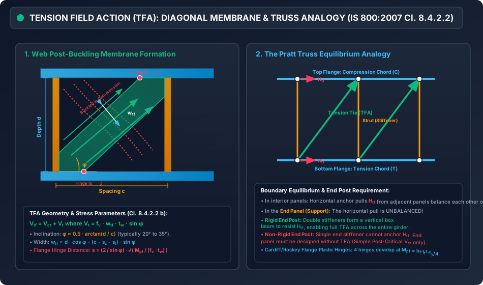
FIGURE STEEL-05-02B: Mohr's Circle Yield Criterion & Cardiff 4-Hinge Mechanism
The following diagram demonstrates the stress state transformation on Mohr's plane from pre-buckling pure shear to the von Mises yield ellipse, alongside the Rockey-Cardiff 4-hinge plastic collapse mechanism in the boundary flanges.

8. Complete Step-by-Step Mathematical Derivations
Derivation 1: Von Mises Yield Criterion for Membrane Tension Field Stress
Consider a web plate element within the diagonal tension band after elastic buckling has occurred. The stress state consists of:
- Pre-buckling pure shear stress acting along the girder's orthogonal coordinate axes.
- A post-buckling uniaxial membrane tensile stress acting at an inclination angle to the horizontal -axis.
Transforming the uniaxial tension into orthogonal Cartesian stress components ( coordinates):
The von Mises yield criterion for plane stress () states:
Substitute the stress expressions into the yield criterion:
Using the identity :
Now expanding the shear term :
Summing both parts:
Notice the cancelation of the terms:
Define the parameter :
The equation becomes a standard quadratic equation in :
Solving using the quadratic formula:
Rearranging into the standard IS 800:2007 form:
Derivation 2: Flange Plastic Mechanism & Anchorage Length (Cardiff Model)
Consider the top flange behaving as a beam spanning between two transverse stiffeners spaced at . The diagonal membrane tension pulls downwards on the flange with an inward normal traction component .
Under this transverse traction, a virtual displacement is applied to the flange plastic mechanism.
- Two plastic hinges form in the flange: one at the stiffener node () and one at distance ().
- The internal plastic work done in the two plastic hinges is:
- The external work done by the inward membrane pull over the anchorage length is:
- Equating internal and external virtual work ():
9. Multi-Exam Comprehensive Solved Examples
Example 1: Full Tension Field Action Capacity (GATE CE / ESE Conventional)
Problem Statement: A welded plate girder fabricated from Fe 410 steel () has a clear web depth and web thickness . Intermediate vertical transverse stiffeners are provided at a uniform spacing (aspect ratio ). The flanges are . Assume , , and .
- Compute the elastic critical shear buckling stress and shear buckling stress .
- Determine the simple post-critical shear capacity .
- Calculate the tension field stress , flange hinge distance , and tension field width .
- Determine the total design shear capacity mobilized by Tension Field Action.
- Calculate the percentage increase in shear capacity gained through TFA over the simple post-critical capacity.
Solution:
Step 1: Plate Slenderness & Buckling Coefficient
- Web slenderness ratio:
- Panel aspect ratio:
- For , the shear buckling coefficient is:
Step 2: Critical Elastic Shear Buckling Stress
Step 3: Shear Buckling Stress
- Yield shear stress:
- Non-dimensional web slenderness :
- Since , elastic buckling governs:
Step 4: Simple Post-Critical Shear Capacity
- Web shear area:
- Design pre-buckling shear strength:
Step 5: Tension Field Inclination Angle
Step 6: Tension Field Stress
- Calculate parameter :
- Evaluate terms inside radical:
- Diagonal membrane tension:
Step 7: Flange Plastic Moment Resistance & Anchorage Length
- Plastic moment capacity of flange plate:
- Anchorage length :
- Since , the plastic hinge forms within the panel.
Step 8: Width of Tension Field Band
Step 9: Post-Buckling Tension Shear & Total Capacity
- Tension field nominal shear:
- Factored design tension shear:
- Total design shear capacity:
Step 10: Performance Evaluation
- Full plastic shear capacity limit: Since , the capacity is valid.
- Percentage capacity gain from TFA: Tension Field Action more than doubles the shear carrying capacity of the girder!
Example 2: Effect of Transverse Stiffener Spacing ( Ratio)
Problem Statement: Using the plate girder properties from Example 1 (), compare the shear capacities for three different transverse stiffener spacings:
- Case A: (, close spacing)
- Case B: (, square panel)
- Case C: (, wide spacing)
Solution (Summary of Parametric Pre-Calculations):
Key Engineering Insight: Reducing the stiffener spacing from to increases the total shear capacity from to (a increase). Both the pre-buckling capacity and the post-buckling capacity rise significantly as stiffeners are brought closer together.
Example 3: End Panel Anchoring & Rigid End Post Design
Problem Statement: A plate girder designed using Fe 410 steel has , , and . The factored support shear force is .
- Can a Non-Rigid End Post be used at the support?
- If a Rigid End Post is provided, calculate the horizontal anchor thrust that it must resist and the resulting bending moment .
Solution:
Part 1: Non-Rigid End Post Feasibility Check
- Under IS 800:2007 Cl. 8.5.3, if a non-rigid end post is used, Tension Field Action is strictly prohibited in the end panel.
- The end panel capacity is restricted to the Simple Post-Critical capacity:
- Applied factored shear at support:
- Comparison: Conclusion: A non-rigid end post is completely inadequate. A Rigid End Post is mandatory.
Part 2: Rigid End Post Design Forces
- With a rigid end post, full Tension Field Action is mobilized in the end panel:
- From Example 1, the tension field parameters are:
- The horizontal anchor thrust exerted by the tension field is:
- Factored horizontal anchor thrust:
- The rigid end post spans vertically as a beam between the flanges ().
- The design bending moment in the rigid end post is:
- The twin stiffeners forming the rigid end post must be sized to provide an elastic/plastic section modulus .
10. Exam Traps, Common Pitfalls & Field Failure Modes
Trap 1: Assuming Tension Field Action Always Exists
- The Trap: Students frequently assume that any stiffened plate girder automatically mobilizes Tension Field Action.
- The Reality: Tension Field Action cannot develop if:
- (web is stocky and yields in plastic shear before buckling).
- The aspect ratio (panel is too wide to anchor the diagonal tension).
- The end panel lacks a Rigid End Post (unanchored end boundary).
- Flanges are too flexible to sustain the vertical tension pull without buckling inwards.
Trap 2: Stiffener Spacing Aspect Ratio Formula Inversion
- In the Bryan formula for :
- For : (Note: 4.0 is the base constant).
- For : (Note: 5.35 is the base constant).
- Inverting these formulas in exams results in severe errors in and .
Trap 3: Confusion Between and
- Total nominal capacity: .
- Design shear capacity: where .
- In competitive multiple-choice exams, examiners often provide both nominal and factored values as options!
Trap 4: Neglecting the Flange Thickness Influence
- Examiners frequently ask: "If flange thickness is doubled, does shear capacity change?"
- Common Mistake: Answering "No, because shear is carried only by the web."
- Correction: In Tension Field Action, doubling quadruples the flange plastic moment . This doubles the anchorage length , widening the tension field band and substantially increasing !
11. Comparative Synthesis & Summary Matrix
12. Official Exam Practice Questions
Question 1 (GATE CE)
In a plate girder with web depth and stiffener spacing , the shear buckling coefficient according to IS 800:2007 is:
- (A) 5.35
- (B) 9.35
- (C) 13.51
- (D) 7.60
Detailed Solution:
- Aspect ratio:
- Since :
- Correct Answer: (C)
Question 2 (UPSC ESE)
Consider the following statements regarding Tension Field Action in plate girders:
- The web plate behaves similarly to the diagonal tension ties in a Pratt truss.
- Flanges with high flexural rigidity increase the width of the diagonal tension field.
- An unanchored non-rigid end post allows the end panel to mobilize full tension field action.
- The inclination of the tension field is approximately .
Which of these statements are CORRECT?
- (A) 1, 2, and 3 only
- (B) 1, 2, and 4 only
- (C) 2, 3, and 4 only
- (D) 1, 3, and 4 only
Detailed Solution:
- Statement 1 is TRUE (Pratt truss analogy).
- Statement 2 is TRUE ( wider ).
- Statement 3 is FALSE (A non-rigid end post cannot anchor the tension field; TFA is prohibited in end panels without a rigid end post).
- Statement 4 is TRUE ( per IS 800:2007).
- Correct Answer: (B)
Question 3 (SSC JE)
For an unstiffened web panel of infinite length (), the theoretical minimum shear buckling coefficient is:
- (A) 4.00
- (B) 5.35
- (C) 9.35
- (D) 1.00
Detailed Solution:
- For , .
- As , the second term .
- Thus, .
- Correct Answer: (B)
Question 4 (State AE / RRB JE)
In IS 800:2007, the plastic moment resistance of a plate girder flange utilized in tension field calculations is given by:
- (A)
- (B)
- (C)
- (D)
Detailed Solution:
- The plastic section modulus of a rectangular flange plate bending about its minor axis (thickness direction) is:
- The nominal plastic moment resistance is .
- Correct Answer: (A)
Question 5 (UPSC ESE Conventional)
Explain why an end panel of a plate girder cannot develop tension field action unless provided with a rigid end post. Derive the horizontal anchor force that a rigid end post must sustain.
Detailed Solution:
- In interior panels, adjacent tension fields pull with equal and opposite horizontal components on the intermediate transverse stiffeners, self-equilibrating the horizontal thrust.
- In an end panel, there is no adjacent web panel to counterbalance the horizontal pull of the diagonal tension field.
- If only a standard bearing stiffener is provided (non-rigid end post), the horizontal pull causes the end of the girder to pull inward, causing premature lateral collapse of the web before the diagonal tension can mobilize.
- When a Rigid End Post (consisting of two vertical stiffeners forming a rigid vertical box or beam) is installed, it resists this horizontal force through vertical beam action spanning between the top and bottom flanges.
- The horizontal anchor force is derived by integrating the horizontal component of the membrane tension across the panel height:
- The rigid end post is then designed for the maximum bending moment , ensuring complete boundary anchorage.