Slab Base Design, Concrete Bearing Pressure & Connection Detailing
In this chapter (3 topics)
On this page
- 1. Topic Metadata
- 2. Executive Summary & Core Engineering Significance
- 3. Classification of Column Bases & Load Transfer Mechanics
- 3.1 Slab Bases
- 3.2 Gusseted Bases
- 4. Bearing Pressure on Concrete Pedestal (IS 456 & IS 800:2007 Cl. 7.4.1)
- 4.1 Permissible Bearing Strength in Limit State Design
- 4.2 Required Area of Slab Base Plate
- 4.3 Optimum Proportioning of Base Plate Dimensions
- 5. Complete Mathematical Derivation of Minimum Slab Base Thickness
- 5.1 Cantilever Bending Moments
- 5.2 Poisson's Ratio & Bi-Directional Curvature Interaction
- 5.3 Design Moment Resistance of the Plate
- 5.4 Equating Design Moment to Factored Resistance
- 5.5 The Mandatory Flange Thickness Guardrail
- 6. Connection Detailing: Machined Ends vs. Unmachined Ends & Fasteners
- 6.1 Welded Connection Design
- 6.2 Bolted Connection via Cleat Angles
- 7. Bedding Grout, Friction Resistance & Anchor Bolt Detailing
- 7.1 Bedding Grout Layer
- 7.2 Frictional Resistance against Base Shear
- 7.3 Anchor Bolts (Holding-Down Bolts)
- 8. Visual Architecture & Structural Diagrams
- 8.1 Plan View Geometry, Cantilever Projections & Moment Sections
- 8.2 Load Transfer Mechanisms, Concrete Bearing & Anchor Detailing
- 9. Solved Practical Design Examples
- Problem 1: Standard ISHB 300 Slab Base Design with Machined End (Complete Code Workflow)
- Problem 2: Heavy Column Slab Base with Unequal Projections
- Problem 3: Base Shear Resistance & Anchor Bolt Detailing
- 10. Critical Examination Traps, Pitfalls & Countermeasures
- 11. Multi-Exam Practical Assessment Questions
- Question 1 (GATE CE - Code Formula Derivation)
- Question 2 (UPSC ESE Paper 1 - Load Transfer Percentage)
- Question 3 (SSC JE - Bearing Strength of Concrete)
- Question 4 (State AE - Base Plate Guardrail)
- Question 5 (RRB JE - Anchor Bolt Embedment)
- 12. Comprehensive Standard Specifications & Academic References
1. Topic Metadata
- Subject: Design of Steel Structures (IS 800:2007)
- Module: Chapter 07: Column Bases and Foundations
- Topic ID:
STEEL-07-01 - Syllabus Coverage: GATE CE (Structural Engineering), UPSC ESE (Paper 1), SSC JE (Civil), State AE/JE, RRB JE
- Governing Standard: IS 800:2007 (Section 7: Design of Compression Members, Clause 7.4: Column Bases), IS 456:2000 (Plain and Reinforced Concrete, Clause 34.4), AISC 360-16 (Steel Design Guide 1: Base Plate and Anchor Rod Design), EN 1993-1-8 (Eurocode 3: Design of Joints)
- Prerequisites:
STEEL-03-01(Axially Loaded Compression Members),STEEL-01-02(Welded Connections)
2. Executive Summary & Core Engineering Significance
In any framed steel structure, column bases serve as the vital transition interface between high-strength structural steel columns (bearing stresses up to ) and relatively low-strength concrete foundations or masonry footings (bearing strengths typically ). Without an adequately proportioned steel base plate, the highly concentrated axial load in the column would cause catastrophic local crushing or punching failure in the concrete substructure.
Key engineering fundamentals of slab base design include:
- Load Dispersion: Spreading the intense point-like column force over a broad rectangular footprint such that the concrete bearing pressure does not exceed the limit state bearing strength of concrete ().
- Two-Way Cantilever Bending: Under upward concrete bearing pressure, the base plate acts as a cantilever projecting outward from the column perimeter. The maximum bending moment at the critical section accounts for Poisson's ratio interaction between the two orthogonal directions: .
- IS 800 Thickness Criterion: The minimum plate thickness must be strictly enforced, with the legal caveat that shall never be less than the column flange thickness ().
- Faced vs. Unfaced Load Transfer: The code explicitly distinguishes between column ends machined for full contact bearing (where of the compressive force is transferred via direct metal-to-metal bearing, and via welds/bolts) versus saw-cut/unmachined ends (which mandate transfer through welds or fasteners).
3. Classification of Column Bases & Load Transfer Mechanics
                             STEEL COLUMN BASES
                                     │
           ┌─────────────────────────┴─────────────────────────┐
           ▼                                                   ▼
       SLAB BASES                                       GUSSETED BASES
  (Light to Medium Loads)                           (Heavy Loads & Moments)
• Axial compression with zero/small M              • Heavy axial columns, built-up sections
• Simple rectangular plate                         • Gusset plates + gusset angles
• Cantilever action from column face               • Reduces cantilever overhang projection
• Economical fabrication                           • Controls base plate thickness
3.1 Slab Bases
A slab base consists of a single solid steel plate placed directly underneath the column. It is employed when:
- The column carries primarily axial compression.
- Bending moments are negligible ().
- Column sections are standard rolled I-sections (ISHB, ISMB) or structural tubes (CHS, SHS).
- The required plate thickness remains within standard commercial plate rolling limits ( to ).
3.2 Gusseted Bases
When the column carries very heavy axial loads (typically ) or significant bending moments, the cantilever projections and become large, resulting in excessive plate thickness (). In a gusseted base:
- Vertical gusset plates and gusset angles are attached to the column flanges and web.
- The cantilever overhang of the base plate is supported on three or four sides, drastically reducing the effective cantilever span and plate bending moment.
4. Bearing Pressure on Concrete Pedestal (IS 456 & IS 800:2007 Cl. 7.4.1)
4.1 Permissible Bearing Strength in Limit State Design
When a steel base plate bears upon a concrete foundation pedestal, the concrete immediately below the plate is in a state of triaxial confinement. According to IS 456:2000 Clause 34.4 and IS 800:2007 Clause 7.4.1:
where is the characteristic 28-day cube compressive strength of the concrete pedestal.
========================================================================================
PERMISSIBLE BEARING STRENGTH OF CONCRETE SUBSTRUCTURE (IS 800 / IS 456)
----------------------------------------------------------------------------------------
Concrete Grade            Characteristic Strength (fck)     Design Bearing Strength (0.45 fck)
----------------------------------------------------------------------------------------
M15                       15.0 N/mm²                        6.75 N/mm²
M20                       20.0 N/mm²                        9.00 N/mm²
M25                       25.0 N/mm²                        11.25 N/mm²
M30                       30.0 N/mm²                        13.50 N/mm²
M35                       35.0 N/mm²                        15.75 N/mm²
M40                       40.0 N/mm²                        18.00 N/mm²
========================================================================================
4.2 Required Area of Slab Base Plate
For a column carrying factored axial compressive load :
where:
- is the length of the base plate parallel to the column depth .
- is the width of the base plate parallel to the column flange width .
4.3 Optimum Proportioning of Base Plate Dimensions
Let be the major projection of the base plate beyond the column profile parallel to the depth (), and be the minor projection parallel to the flange width ():
The total plate area is:
To minimize the required plate thickness , the bending moments in the two orthogonal directions should be balanced. This occurs when the projections are nearly equal:
Setting in the area formula yields a simple quadratic equation to solve for the optimum projection:
Once standard plate dimensions and are selected, the actual uniform upward bearing pressure is computed as:
5. Complete Mathematical Derivation of Minimum Slab Base Thickness
The classic formula codified in IS 800:2007 Clause 7.4.3.1 represents an exact application of thin-plate flexure theory under two-way bending.
                      COLUMN FLANGE
                  │  (Section X-X)
                  │ ◄────── a ──────►
                  ┌─────────────────┐
                  │                 │ ▲
                  │   CANTILEVER    │ │
                  │      PLATE      │ │ Unit Width
                  │    OVERHANG     │ │ (b0 = 1 mm)
                  │                 │ ▼
                  └─────────────────┘
                  ▲ ▲ ▲ ▲ ▲ ▲ ▲ ▲ ▲ ▲
                  │ │ │ │ │ │ │ │ │ │
                  w (Upward Pressure)
5.1 Cantilever Bending Moments
Consider the slab base plate acting as a cantilever projecting beyond the faces of the column:
- Along the greater projection (cantilever length ): The upward pressure produces a cantilever bending moment per unit width () at the critical section (face of the column flange, Section X-X):
- Along the lesser projection (cantilever length ): Similarly, at the face of the column web (Section Y-Y), the cantilever bending moment per unit width is:
5.2 Poisson's Ratio & Bi-Directional Curvature Interaction
In a two-dimensional plate element, bending in one direction produces an anticlastic transverse curvature proportional to Poisson's ratio . According to plate theory (Timoshenko & Woinowsky-Krieger), when both and act concurrently, the net design bending moment at the root of the greater projection is:
For structural steel undergoing plastic deformation at the limit state, Poisson's ratio is taken as :
5.3 Design Moment Resistance of the Plate
Per IS 800:2007 Clause 8.2.1.2, the design flexural strength of a solid rectangular plate of thickness and unit width () subjected to bending is:
where:
Substituting :
5.4 Equating Design Moment to Factored Resistance
For limit state safety, :
Solving for :
Taking the square root:
5.5 The Mandatory Flange Thickness Guardrail
IS 800:2007 Clause 7.4.3.1 explicitly mandates:
where is the flange thickness of the compression column. If the calculated from the flexural equation is less than , the plate thickness must be increased such that to prevent local punching shear distress through the plate.
6. Connection Detailing: Machined Ends vs. Unmachined Ends & Fasteners
The structural connection between the lower end of the column and the slab base plate is governed by IS 800:2007 Clause 7.4.1.
+---------------------------------------------------------------------------------------+
|                             IS 800:2007 CLAUSE 7.4.1 RULES                            |
+---------------------------------------------------------------------------------------+
|  CONDITION 1: MACHINED / FACED ENDS IN BEARING                                        |
|  • Column end saw-cut and milled perfectly flat; base plate machined smooth.          |
|  • Load Transfer: 50% transferred by DIRECT METAL-TO-METAL BEARING.                   |
|  • Connection: Welds or fasteners designed for only 50% OF AXIAL LOAD.                |
|  • Highly economical weld sizes (typically 6 mm or 8 mm fillet welds).                |
+---------------------------------------------------------------------------------------+
|  CONDITION 2: UNMACHINED / UNFACED ENDS                                               |
|  • Column end flame-cut or rough saw-cut with surface irregularities.                 |
|  • Load Transfer: 0% direct bearing credit (gap potential exists).                    |
|  • Connection: Welds or fasteners must be designed for 100% OF FACTORED AXIAL LOAD.   |
|  • Requires heavy continuous all-around fillet welds or deep penetration groove welds.|
+---------------------------------------------------------------------------------------+
6.1 Welded Connection Design
When column ends are attached directly to the slab base plate via continuous fillet welds:
- Design Shear Strength of Fillet Weld (IS 800 Cl. 10.5.7): where is the effective throat thickness for right-angle welds, and (shop weld).
- For Fe 410 steel ():
- Required Weld Length: where (for faced ends) or (for unfaced ends).
- The total perimeter available for welding around a standard rolled I-section is:
6.2 Bolted Connection via Cleat Angles
Alternatively, column-to-base connections can be effected using two nominal cleat angles (e.g., ISA or ISA ) bolted or welded to the column flanges:
- Bolts connecting cleat angle to column flange are in single shear.
- Bolts connecting cleat angle to slab base plate are in tension/shear.
7. Bedding Grout, Friction Resistance & Anchor Bolt Detailing
7.1 Bedding Grout Layer
A gap of is deliberately maintained between the bottom of the steel base plate and the top of the rough-finished concrete pedestal during erection.
- Function: Compensates for foundation casting tolerances and enables precise plumb leveling of the column using leveling shims or leveling nuts.
- Material: Non-shrink, high-strength cementitious or epoxy grout (minimum compressive strength ).
- Air Vent Holes: For base plates exceeding in width, one or more central grout/air vent holes ( diameter) must be drilled to prevent trapped air pockets and ensure solid bedding.
7.2 Frictional Resistance against Base Shear
In slab bases subjected to concurrent horizontal base shear (from wind drag or seismic frame action):
- The coefficient of static friction between steel base plate and cementitious grout is:
- The design frictional resistance developed under factored compressive load is:
- If , friction alone completely resists the base shear without requiring shear keys or anchor bolt dowel action!
7.3 Anchor Bolts (Holding-Down Bolts)
For slab bases carrying purely axial compression:
- Nominal Function: Anchor bolts are not required to resist calculated working tension. They serve strictly to stabilize the column during erection, prevent accidental displacement from crane hooks, and secure alignment before grouting.
- Sizing: Minimum 2 bolts (for light columns) or 4 bolts (for medium/heavy columns) of diameter or (Grade 4.6 steel).
- Embedment Length (): To prevent pull-out failure from concrete, the minimum embedment depth is: terminated with a standard anchor hook or a heavy welded anchor washer plate.
- Washer Plates: Heavy square steel washers (e.g., or ) are placed under the nuts to cover standard oversized base plate holes () and prevent local plate gouging.
8. Visual Architecture & Structural Diagrams
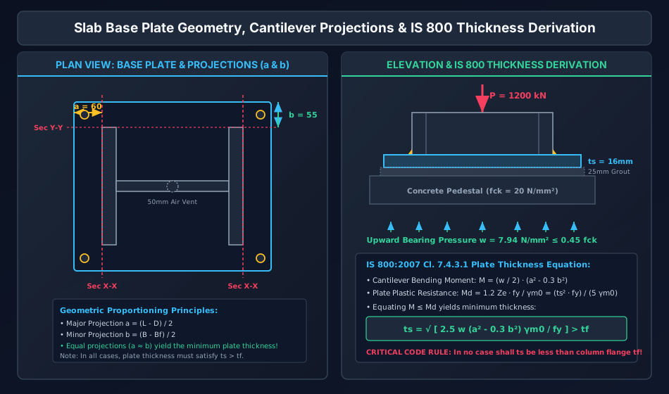
8.1 Plan View Geometry, Cantilever Projections & Moment Sections
The diagram below details the plan layout of an ISHB 300 column on a slab base plate, showing major projection , minor projection , critical flexural sections, anchor bolt locations, and central air vent holes:
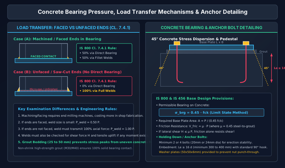
8.2 Load Transfer Mechanisms, Concrete Bearing & Anchor Detailing
The diagram below illustrates the direct bearing rule for faced ends vs. weld requirement for unfaced ends, stress dispersion into concrete, grout bedding, and anchor bolt detailing:
9. Solved Practical Design Examples
Problem 1: Standard ISHB 300 Slab Base Design with Machined End (Complete Code Workflow)
Problem Statement: Design a slab base for an ISHB 300 @ 58.8 kg/m column carrying a factored axial compressive load .
- Column properties: Overall depth , flange width , flange thickness , web thickness .
- Concrete foundation pedestal: Grade M20 ().
- Steel base plate: Fe 410 ().
- Column end and base plate are machined for full contact bearing. Determine:
- Permissible concrete bearing strength and required base plate area.
- Optimum plan dimensions and , and projections and .
- Actual uniform upward bearing pressure .
- Minimum base plate thickness per IS 800 Cl. 7.4.3.1 and verify against .
- Sizing and detailing of the shop-welded fillet connection.
Step-by-Step Mathematical Solution:
Step 1: Permissible Bearing Strength & Area of Base Plate
- Design bearing strength of M20 concrete (IS 800 Cl. 7.4.1):
- Minimum required plate area:
Step 2: Proportioning Base Plate Dimensions ()
- To minimize plate thickness, balance projections :
- Select practical rounded plate dimensions:
- Provide length parallel to depth:
- Provide width parallel to flange:
- Provided Area:
- Actual projections:
Step 3: Actual Upward Bearing Pressure ()
Step 4: Minimum Thickness of Slab Base Plate ()
- Critical cantilever moment term:
- Minimum thickness per IS 800:2007 Cl. 7.4.3.1:
- Flange thickness guardrail:
- Provide a standard commercial base plate of thickness . (Final Base Plate Specification: plate).
Step 5: Welded Connection Design (Machined Ends)
- Since column end and base plate are machined for direct contact, per IS 800 Cl. 7.4.1:
- Direct metal-to-metal bearing carries: .
- Fillet welds are designed to transfer: .
- Provide continuous shop fillet weld:
- Throat thickness: .
- Design shear strength per mm length ():
- Required effective weld length:
- Available welding length along column flanges alone: Since , continuous fillet welds on the outer and inner faces of the column flanges are fully adequate!
Problem 2: Heavy Column Slab Base with Unequal Projections
Problem Statement: A heavy built-up column carries a factored axial compressive load . The overall column dimensions are depth , flange width , with flange thickness . The foundation pedestal is cast from M25 concrete ().
- Determine the required base plate area.
- If space constraints dictate a base plate size of , determine projections and , and check concrete bearing pressure.
- Compute the required base plate thickness .
Step-by-Step Mathematical Solution:
Step 1: Permissible Concrete Bearing Strength & Area
- Design bearing strength of M25 concrete:
- Minimum required plate area:
Step 2: Geometry & Bearing Pressure for Plate
- Provided Area:
- Projections:
- Actual bearing pressure:
Step 3: Minimum Thickness Calculation
- Moment term:
- Minimum thickness per IS 800 Cl. 7.4.3.1:
- Check guardrails:
- Select a standard commercial plate thickness: .
Problem 3: Base Shear Resistance & Anchor Bolt Detailing
Problem Statement: A column slab base carries a factored axial compressive load and a concurrent factored wind shear force at the base interface. The slab base plate is set on an M20 concrete pedestal with a non-shrink cementitious grout bed.
- Evaluate whether the horizontal shear force can be resisted by interfacial friction alone.
- Detail the nominal anchor bolts and determine their required embedment length.
Step-by-Step Mathematical Solution:
Step 1: Evaluation of Interfacial Friction Resistance
- Per IS 800 Cl. 7.4.1 and IS 1904, the coefficient of static friction between steel plate and cementitious grout is .
- Design frictional shear resistance:
- Comparison with applied factored shear:
Conclusion: Friction alone provides a factor of safety of against sliding. No shear lugs, shear keys, or anchor bolt shear dowel mechanisms are required.
Step 2: Anchor Bolt Detailing
- Provide 4 Grade 4.6 anchor bolts of diameter positioned symmetrically near the four corners of the base plate for erection alignment and stability.
- Net tensile stress area of bolt: .
- Minimum embedment depth into concrete pedestal: Provide an embedment depth of terminated with a standard hook.
- Provide steel washer plates under the nuts.
10. Critical Examination Traps, Pitfalls & Countermeasures
========================================================================================================================
EXAM TRAP IDENTIFIER                   FATAL ERROR TO AVOID                               CORRECT ENGINEERING PROCEDURE
========================================================================================================================
1. Permissible Bearing Limit           Using 0.45 fck in Working Stress Method (WSM)      In Limit State Method (LSM),
                                       or using 0.25 fck in LSM.                          σ_brg = 0.45 fck (IS 800 / IS 456).
                                                                                          In WSM, σ_brg = 0.25 fck.
------------------------------------------------------------------------------------------------------------------------
2. Faced Ends Weld Design Sizing       Designing welds for 100% of the factored axial     IS 800 Cl. 7.4.1 explicitly states:
                                       load when column ends are machined/faced.          If ends are faced for bearing, welds
                                                                                          are designed for ONLY 50% of axial load!
------------------------------------------------------------------------------------------------------------------------
3. Unfaced Ends Bearing Credit         Assuming 50% direct bearing when column ends       If ends are NOT machined, zero direct
                                       are flame-cut or unfaced.                          bearing is permitted. Welds must resist
                                                                                          100% of the factored compressive load.
------------------------------------------------------------------------------------------------------------------------
4. Mandatory Flange Thickness Check    Selecting a base plate thinner than the column     The code strictly requires ts > tf.
                                       flange (ts < tf) because flexural math yielded     Even if flexural formula gives 8 mm, if
                                       a small value.                                     tf = 12 mm, ts MUST be at least 12 mm!
------------------------------------------------------------------------------------------------------------------------
5. Projection Term Signs (a² vs b²)    Writing the moment term as (a² + 0.3 b²).          The Poisson's interaction is SUBTRACTIVE:
                                                                                          (a² - 0.3 b²), where a is the LARGER
                                                                                          and b is the SMALLER projection.
========================================================================================================================
11. Multi-Exam Practical Assessment Questions
Question 1 (GATE CE - Code Formula Derivation)
In the limit state design of a steel slab base under IS 800:2007, the minimum thickness of the base plate is given by:
- (A)
- (B)
- (C)
- (D)
Answer: (A) Detailed Solution: Per IS 800:2007 Clause 7.4.3.1, the minimum thickness of a slab base plate is , where and are the greater and lesser projections beyond the column profile, is the uniform bearing pressure, and must exceed .
Question 2 (UPSC ESE Paper 1 - Load Transfer Percentage)
When the column end and the base plate in a steel column base are machined for full and complete contact bearing, the connection (welds or fasteners) between the column and base plate shall be designed to transmit:
- (A) of the axial load
- (B) of the axial load
- (C) of the axial load
- (D) of the axial load
Answer: (C) Detailed Solution: Per IS 800:2007 Clause 7.4.1, where the column ends and base plates are machined for full contact bearing, of the compressive load is taken as transmitted by direct bearing, and the connection shall be designed to transmit the remaining of the load.
Question 3 (SSC JE - Bearing Strength of Concrete)
According to IS 800:2007, the permissible design bearing strength of concrete in limit state method is taken as:
- (A)
- (B)
- (C)
- (D)
Answer: (C) Detailed Solution: Per IS 800:2007 Clause 7.4.1 and IS 456:2000 Clause 34.4, the bearing strength of concrete in limit state design is . (Note: is the working stress limit).
Question 4 (State AE - Base Plate Guardrail)
A steel column with flange thickness is supported on a slab base. The calculated plate thickness from the flexural equation is . The minimum thickness of the slab base plate to be provided is:
- (A)
- (B)
- (C) Greater than
- (D)
Answer: (C) Detailed Solution: IS 800:2007 Clause 7.4.3.1 explicitly stipulates that the thickness of a slab base plate shall in no case be less than the flange thickness of the column it supports (). Since , must exceed (e.g., provide ).
Question 5 (RRB JE - Anchor Bolt Embedment)
What is the minimum embedment length of an anchor bolt in a concrete pedestal to resist pull-out forces?
- (A)
- (B)
- (C)
- (D)
Answer: (C) Detailed Solution: Per standard structural practice and code detailing guidelines (IS 800 / IS 5624), anchor bolts embedded in concrete foundations must have a minimum development/embedment length of (where is the bolt diameter) terminated with a standard hook or anchor plate.
12. Comprehensive Standard Specifications & Academic References
- Bureau of Indian Standards (BIS):
- IS 800:2007: General Construction in Steel — Code of Practice (Third Revision). Section 7 (Clause 7.4: Column Bases, Cl. 7.4.1 & 7.4.3.1); Section 10 (Connections).
- IS 456:2000: Plain and Reinforced Concrete — Code of Practice (Fourth Revision). Clause 34.4 (Bearing Stresses on Concrete).
- IS 5624:1993: Specification for Foundation Bolts.
- American Institute of Steel Construction (AISC):
- AISC 360-16: Specification for Structural Steel Buildings. Chapter J (Design of Connections).
- AISC Design Guide 1: Base Plate and Anchor Rod Design (Second Edition). American Institute of Steel Construction, Chicago.
- European Committee for Standardization (CEN):
- EN 1993-1-8:2005 (Eurocode 3): Design of Steel Structures — Part 1-8: Design of Joints. Section 6.2.8 (Column Bases).
- Foundational Academic Textbooks:
- Subramanian, N. (2016). Design of Steel Structures (Limit State Method). Oxford University Press.
- Duggal, S. K. (2019). Limit State Design of Steel Structures. McGraw-Hill Education.
- Dayaratnam, P. (2018). Design of Steel Structures. S. Chand Publishing.