Column Bases: Slab Base and Gusseted Base Design
In this chapter (4 topics)
On this page
- 1. TOPIC METADATA & OVERVIEW
- 2. CODE CLAUSES & STATUTORY PROVISIONS (IS 800:2007 & IS 456:2000)
- 2.1 General Requirements for Column Bases — Clause 7.4.1
- 2.2 Permissible Bearing Strength of Concrete (qc) — Clause 7.4.1 & IS 456:2000 Cl. 34.4
- 2.3 Slab Base Design Provisions — Clause 7.4.3.1
- 2.4 Gusseted Base Design Provisions — Clause 7.4.3.2
- 2.5 Load Transfer Modes & Fastener Provisions — Clause 7.4.1
- 3. PHYSICAL MECHANICS & FUNDAMENTAL THEORY
- 3.1 Mechanics of Biaxial Cantilever Bending in Base Plates
- 4. MATHEMATICAL DERIVATIONS & EXACT FORMULATIONS
- 4.1 Derivation of Slab Base Plate Thickness Formula (ts)
- 4.2 Derivation of Gusseted Base Thickness Formula (tg)
- 4.3 Combined Axial Load and Bending Moment (P + M) Mechanics
- 5. STRUCTURAL DETAILING, ASSEMBLY & FASTENER RULES
- 6. HIGH-IMPACT VISUAL ARCHITECTURE
- 6.1 Slab Base Plan, Elevation & Bending Projections
- 6.2 Gusseted Base Structural Assembly & Eccentric Bearing
- 7. CODE NUANCES, EXCEPTIONS & DESIGN GUARDRAILS
- 7.1 Milled vs Unmilled Column Ends (The 50% Rule)
- 7.2 Non-Shrink Grout Layer (25 mm to 50 mm)
- 8. STANDARD WORKED NUMERICAL EXAMPLES
- 8.1 Example 1: Comprehensive Design of a Slab Base
- 8.2 Example 2: Comprehensive Design of a Gusseted Base
- 8.3 Example 3: Base Plate Under Combined Axial Load and Moment (P + M)
- 9. COMPARATIVE ANALYSIS: SLAB BASE VS GUSSETED BASE
- 10. COMMON PITFALLS, SITE ERRORS & EXAMINATION TRAPS
- 10.1 Trap 1: Confusing Permissible Concrete Bearing Values (0.45 fck vs 0.25 fck)
- 10.2 Trap 2: Neglecting the ts > tf Lower Bound
- 10.3 Trap 3: Identifying Larger vs Smaller Projections (a vs b)
- 11. MULTI-EXAM PREPARATION MATRIX
- 12. COMPREHENSIVE REFERENCES & CROSS-LINKING
1. TOPIC METADATA & OVERVIEW
- Subject: Design of Steel Structures (IS 800:2007)
- Module: Chapter 03 — Design of Compression Members
- Topic ID: STEEL-03-04
- Topic Title: Column Bases: Slab Base and Gusseted Base Design (IS 800:2007 Cl. 7.4)
- Prerequisites: STEEL-03-01 (Buckling Curves), STEEL-03-02 (Effective Length & Restraints), STEEL-03-03 (Built-up Columns)
- Target Examinations: GATE CE, UPSC ESE, SSC JE, RRB JE, State PSC AE/JE
- Key Reference Codes: IS 800:2007 (Cl. 7.4, 7.4.1, 7.4.2, 7.4.3), IS 456:2000 (Cl. 34.4), SP 6(1)
2. CODE CLAUSES & STATUTORY PROVISIONS (IS 800:2007 & IS 456:2000)
2.1 General Requirements for Column Bases — Clause 7.4.1
Column bases provide the physical interface between structural steelwork and concrete substructures:
- Steel columns transmit heavy concentrated compressive axial forces (), shear forces (), and overturning bending moments () over small cross-sectional areas (typical steel stress: ).
- Concrete foundation pedestals (typically Grade M20 to M30) have much lower compressive bearing capacities.
- Column bases spread these loads safely over a sufficiently large concrete footprint so that the permissible bearing strength of concrete is not exceeded.
2.2 Permissible Bearing Strength of Concrete () — Clause 7.4.1 & IS 456:2000 Cl. 34.4
In Limit State Design, the design bearing strength of concrete beneath a steel base plate is:
Where:
- is the characteristic 28-day compressive cube strength of concrete (in or ).
- Confinement Dispersion Bonus: If the concrete pedestal area is larger than the base plate area , the bearing strength may be multiplied by , capped at . However, for conservative base plate sizing, is universally adopted.
- Required Base Plate Plan Area (): Where is the factored axial compressive design load.
2.3 Slab Base Design Provisions — Clause 7.4.3.1
Slab bases are used for columns subjected to primarily axial loads or small eccentricities.
1. Minimum Thickness of Slab Base Plate ()
When the projection of the base plate beyond the column face is in one direction and in the perpendicular direction:
Where:
- is the actual uniform bearing pressure beneath the base plate ().
- is the larger projection of the plate beyond the column face (typically along the depth of the column).
- is the smaller projection of the plate beyond the column face (typically along the width of the flange).
- is the yield strength of the steel plate (typically for Fe 410).
- is the partial safety factor against yielding.
- is the flange thickness of the column section.
[!IMPORTANT] Mandatory Statutory Guardrail: In no case shall the base plate thickness be less than the column flange thickness (). If the calculated , the code explicitly mandates providing to prevent local punching and high stress concentrations.
2.4 Gusseted Base Design Provisions — Clause 7.4.3.2
Gusseted bases are mandatory for columns carrying very heavy axial compressive loads (), built-up columns, or columns subjected to substantial overturning bending moments.
1. Structural Action & Plate Overhang ()
- Vertical gusset plates and horizontal gusset angles are attached to the column flanges/webs, converting the base plate into a multi-stiffened cantilever system.
- The critical cantilever projection of the base plate is , defined as the overhang beyond the vertical face/toe of the gusset angle.
- Minimum Base Plate Thickness ():
- Combined Thickness Rule: When the horizontal leg of a gusset angle rests directly on the base plate and is bolted/welded to it:
2.5 Load Transfer Modes & Fastener Provisions — Clause 7.4.1
- Case A: Column Ends Machined / Milled for Full Bearing:
- Where the column end and base plate are machined to achieve complete flat contact, at least of the compressive load is transferred by direct bearing.
- The fasteners (fillet welds or bolts through cleat angles) need only be designed to transfer the remaining of the axial load, plus any shear or bending moments.
- Case B: Column Ends Not Machined (Rough / Unfinished):
- Where the column ends are not milled, of the axial load, shear, and moments must be transferred entirely through the fasteners/welds. Direct bearing credit is strictly zero!
- Anchor Bolts (Holding-Down Bolts):
- Minimum 2 to 4 bolts (typically or diameter, embedment ) to anchor the column against erection wind loads and accidental lateral displacements.
3. PHYSICAL MECHANICS & FUNDAMENTAL THEORY
================================================================================
              SLAB BASE VS GUSSETED BASE STRUCTURAL MECHANICS
================================================================================
          Slab Base (Axial Loads)               Gusseted Base (Heavy Loads & Moments)
              Column Shaft                            Column Shaft
                   │                                       │
                   │                                ┌──────┼──────┐  Gusset Plate
                   ▼ P                              │      ▼ P    │
          ┌─────────────────┐                       ├──────┬──────┤  Gusset Angle
          │   Base Plate    │                       │   Base Plate│
      ◄───┼─────────────────┼───►               ◄───┼─────────────┼───►
        a │                 │ a                   c │             │ c
       (Large Overhang: 150-250 mm)             (Small Overhang: 50-80 mm)
       Moments large: M = w·a²/2                Moments small: M = w·c²/2
       Requires thick plate (ts > 25 mm)        Thinner plate with stiffener ribs
================================================================================
3.1 Mechanics of Biaxial Cantilever Bending in Base Plates
When a column transmits axial load to a slab base, the base plate presses against the concrete foundation with uniform bearing pressure .
- The concrete pushes back uniformly with pressure .
- The portion of the plate extending beyond the column profile acts as a cantilever slab supported by the rigid column boundary.
- Because the plate projects in two orthogonal directions ( along the depth, along the width), the plate bends biaxially.
- By Poisson's ratio effect, transverse bending in the -direction reduces the longitudinal bending moment in the -direction: Where is Poisson's ratio for structural steel.
4. MATHEMATICAL DERIVATIONS & EXACT FORMULATIONS
4.1 Derivation of Slab Base Plate Thickness Formula ()
Consider a unit width strip ( width) of the base plate projecting distance beyond the column face:
- The maximum cantilever bending moment at the column boundary per unit width is:
- In Limit State Design (IS 800:2007 Cl. 8.2.1.2), the design moment capacity of a solid rectangular plate section of unit width () and thickness is:
Where:
- Elastic section modulus: .
- Plastic section modulus: .
- Using :
- Hence:
- Equating the external cantilever moment to the design moment capacity :
4.2 Derivation of Gusseted Base Thickness Formula ()
In a gusseted base, the plate projection beyond the gusset angle toe is a simple one-way cantilever of span :
- Maximum cantilever bending moment at the toe of the gusset angle:
- The design moment capacity of the plate (elastic-plastic limit per unit width): Using :
4.3 Combined Axial Load and Bending Moment () Mechanics
When a column is subjected to axial load and bending moment , the eccentricity of load is:
Let the base plate have length in the direction of the moment and width :
- Plan area .
- Elastic section modulus .
Case I: No Tension / Complete Bearing ()
When the resultant load falls within the kern of the base plate ():
- Concrete bearing check: .
- Uplift check: (entire base plate remains compressed against concrete).
- Anchor bolts do not carry tension; they serve nominal positioning functions.
Case II: Tension / Uplift on Windward Side ()
When , tensile separation occurs between the base plate and concrete. Concrete cannot resist tension:
- The base plate lifts off, resulting in a triangular compressive stress block of length on the leeward side.
- Anchor bolts on the windward side are mobilized in direct tension .
- From vertical force equilibrium and moment equilibrium about the centroid of the compressive stress block: Where is the lever arm between the anchor bolts and the centroid of the concrete compression stress block.
- Anchor bolts must be designed for tensile capacity:
5. STRUCTURAL DETAILING, ASSEMBLY & FASTENER RULES
================================================================================
             IS 800:2007 STATUTORY COLUMN BASE DETAILING SUMMARY
================================================================================
  Feature                      Slab Base (Cl. 7.4.3.1)          Gusseted Base (Cl. 7.4.3.2)
  ─────────────────────────────────────────────────────────────────────────────
  Load Type                    Primarily Axial (small M)        Heavy Axial + Large Moment
  Concrete Bearing Stress      w ≤ 0.45 fck                     w ≤ 0.45 fck
  Minimum Thickness            ts = √[2.5w(a²-0.3b²)γm0/fy]     tg = c·√[3wγm0/fy]
  Mandatory Lower Bound        ts > tf (flange thickness)       t_base + t_angle ≥ tg
  Gusset Material              None (cleat angles only)         Gusset plates (12-20mm) + angles
  Fastener Load Share (Milled) 50% Bearing, 50% Weld/Bolts      50% Bearing, 50% Weld/Bolts
  Fastener Load Share (Rough)  100% via Weld/Bolts (0% bearing) 100% via Weld/Bolts (0% bearing)
  Grout Layer Thickness        25 to 50 mm (Non-shrink grout)   25 to 50 mm (Non-shrink grout)
  Anchor Bolts                 Min 2-4 bolts (dia ≥ 20 mm)      Min 4-8 bolts (dia ≥ 24 mm)
================================================================================
6. HIGH-IMPACT VISUAL ARCHITECTURE
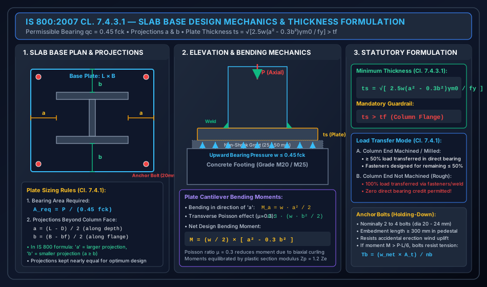
6.1 Slab Base Plan, Elevation & Bending Projections
The diagram below illustrates the plan view of a slab base plate with projections and , side elevation showing grout and pedestal, and the biaxial cantilever bending mechanics.
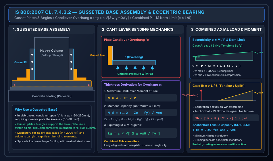
6.2 Gusseted Base Structural Assembly & Eccentric Bearing
The diagram below illustrates the multi-component assembly of a gusseted base (gusset plates, gusset angles, cleat angles), overhang mechanics, and combined stress distributions showing the kern limit ().
7. CODE NUANCES, EXCEPTIONS & DESIGN GUARDRAILS
7.1 Milled vs Unmilled Column Ends (The 50% Rule)
- On site, structural steel fabricators often specify "ends milled for full bearing". If milling is verified by feeler gauge inspection ( gap over of contact area), IS 800 allows of the load to pass directly through steel-to-steel contact.
- If ends are flame-cut or rough, uneven high-spots cause intense stress concentration. In this case, code rules mandate that fasteners/welds must carry of the factored load.
7.2 Non-Shrink Grout Layer (25 mm to 50 mm)
- Steel base plates are never set directly onto cured concrete pedestals because concrete casting tolerances () leave uneven surfaces and air voids.
- Leveling nuts or steel shims are used to align the base plate at the precise elevation, leaving a gap.
- High-strength, non-shrink cementitious or epoxy grout is then pressure-pumped beneath the base plate to ensure 100% void-free monolithic bearing contact.
8. STANDARD WORKED NUMERICAL EXAMPLES
================================================================================
             VERIFIED NUMERICAL CALCULATION SUMMARY (IS 800:2007)
================================================================================
  Example 1: Complete Design of a Slab Base (ISHB 350, P = 1500 kN, Concrete M25)
    • Permissible Concrete Bearing: qc = 0.45 * 25 = 11.25 MPa => A_req = 133333.3 mm²
    • Adopt Plate: 460 x 380 mm (Area = 174800 mm²) => Actual pressure w = 8.581 MPa <= 11.25 MPa
    • Projections: a = 65.0 mm (flange overhang), b = 55.0 mm (web overhang)
    • Bending Term: a² - 0.3 b² = 65² - 0.3(55²) = 4225 - 907.5 = 3317.5 mm²
    • Thickness: ts = √[2.5 * 8.581 * 3317.5 * 1.10 / 250] = 17.70 mm => Adopt ts = 20 mm > tf (11.6 mm) (SAFE!)
    • Welded Joint (50% bearing credit): Weld carries 750 kN over 1637 mm perimeter => 8 mm weld stress = 81.8 MPa <= 189.4 MPa (SAFE!)

  Example 2: Complete Design of a Gusseted Base (Built-up Column, P = 2800 kN, Concrete M20)
    • Permissible Bearing: qc = 0.45 * 20 = 9.00 MPa => A_req = 311111.1 mm²
    • Adopt Plate: 650 x 550 mm (Area = 357500 mm²) => Actual pressure w = 7.832 MPa <= 9.00 MPa
    • Overhang c beyond gusset angle toe: c = 75.0 mm
    • Thickness: tg = 75.0 * √[3 * 7.832 * 1.10 / 250] = 24.12 mm
    • Provided: Base plate 25 mm + Gusset angle leg 15 mm => Total thickness = 40 mm >= 24.12 mm (SAFE!)

  Example 3: Base Plate Under Combined P + M (P = 600 kN, M = 30 kN-m, Plate 500 x 350 mm)
    • Eccentricity: e = M / P = 30 / 600 = 0.050 m = 50.0 mm
    • Kern Limit: L / 6 = 500 / 6 = 83.3 mm => e <= L/6 (NO TENSION / NO UPLIFT!)
    • Bearing Pressures: w_max = 5.486 MPa <= 9.00 MPa (SAFE), w_min = 1.371 MPa > 0
    • Critical Thickness under w_max: ts = 17.15 mm => Adopt ts = 20 mm (SAFE!)
================================================================================
8.1 Example 1: Comprehensive Design of a Slab Base
Problem Statement:
Design a slab base for an ISHB 350 @ 67.4 kg/m column carrying a factored axial compressive load . The column is supported on a reinforced concrete pedestal of Grade M25.
Steel grade Fe 410 (, ).
Properties of ISHB 350:
, , , .
Column ends are machined for full bearing. Design the base plate, welded connection, and anchor bolts.
Step-by-Step Mathematical Solution:
Step 1: Permissible Bearing Pressure & Required Base Area
For M25 concrete (), the design bearing strength (IS 800 Cl. 7.4.1):
Required plan area of base plate:
Step 2: Base Plate Dimensions and Projections
To optimize bending moments, projections and should be nearly equal.
Let length and width :
Actual uniform bearing pressure:
Projections beyond column faces:
- Along depth :
- Along flange width :
Assigning variables per IS 800 Cl. 7.4.3.1 ( is larger, is smaller):
Step 3: Base Plate Thickness Calculation
Using IS 800:2007 Eq. Cl. 7.4.3.1:
Checking code guardrail:
Adopt a base plate of size .
Step 4: Welded Connection Design
Because column ends are machined for full bearing, of the compressive load is transferred by direct bearing:
Available weld perimeter around ISHB 350:
Using an fillet weld ():
Design weld shear strength:
Step 5: Anchor Bolts
Provide 4 No. diameter mild steel holding-down bolts of length at the corners in slotted holes to facilitate alignment and secure against accidental erection forces.
8.2 Example 2: Comprehensive Design of a Gusseted Base
Problem Statement:
Design a gusseted base for a built-up column carrying a factored compressive load . The column consists of 2 ISMC 350 channels placed toe-to-toe with an overall depth and width of .
Concrete grade: M20 (). Steel grade: Fe 410 ().
Gusset plates provided: thick. Gusset angles: ISA (horizontal leg ).
Column ends are machined for full bearing.
Step-by-Step Mathematical Solution:
Step 1: Base Plate Plan Dimensions
Permissible concrete bearing pressure:
Required base plate area:
Adopt plate size: , :
Actual uniform bearing pressure:
Step 2: Cantilever Overhang and Plate Thickness
The vertical gusset plate () and horizontal leg of gusset angle () support the base plate.
The cantilever projection of the base plate extending beyond the toe of the horizontal leg of the gusset angle:
Using IS 800:2007 Cl. 7.4.3.2 formula:
Thickness provided:
Base plate thickness .
Gusset angle leg resting on plate .
Total thickness
Adopt base plate thickness .
Step 3: Gusset Fastener Design
Load transferred by fasteners ( of ):
Gusset plates and angles are connected to the channel webs and flanges with fillet welds () or M24 Class 4.6 bolts to safely transmit .
8.3 Example 3: Base Plate Under Combined Axial Load and Moment ()
Problem Statement:
An ISHB 300 column carries a factored axial compressive load and a bending moment . The column base is supported on M20 concrete ().
The base plate size is (along moment plane) and .
- Check whether tension occurs beneath the base plate.
- Determine maximum and minimum concrete bearing pressures.
- Compute the required plate thickness if overhang and .
Step-by-Step Mathematical Solution:
Step 1: Eccentricity & Kern Limit Check
Eccentricity of resultant force:
Kern limit of rectangular base plate:
Since , the resultant lies entirely within the middle-third (kern) of the base plate!
Step 2: Maximum and Minimum Bearing Pressures
Base plate area: .
Section modulus: .
Direct compressive stress:
Bending compressive stress:
Maximum bearing pressure:
Minimum bearing pressure:
Step 3: Base Plate Thickness under Critical Pressure
With and :
Checking column flange thickness ( for ISHB 300):
Adopt a base plate of thickness .
9. COMPARATIVE ANALYSIS: SLAB BASE VS GUSSETED BASE
| Parameter / Feature | Slab Base (IS 800 Cl. 7.4.3.1) | Gusseted Base (IS 800 Cl. 7.4.3.2) |
|---|---|---|
| Primary Loading | Moderate axial loads (), negligible moments | Heavy axial loads (), large bending moments |
| Column Section Types | Rolled universal beams and columns (ISMB, ISHB) | Built-up channel/plate columns, heavy mill columns |
| Plate Support System | Unstiffened cantilever supported only along column outline | Stiffened by vertical gusset plates and gusset angles |
| Cantilever Span | Large span: () | Small span: beyond gusset angle toe () |
| Governing Formula | ||
| Material Efficiency | Economical for light/medium loads; plate gets excessively thick for high | Highly economical for heavy loads; prevents excessive plate thickness |
| Fabrication Cost | Low (simple rectangular plate, minimal shop cutting) | Higher (requires multiple plates, angles, extensive welding/bolting) |
10. COMMON PITFALLS, SITE ERRORS & EXAMINATION TRAPS
10.1 Trap 1: Confusing Permissible Concrete Bearing Values ( vs )
- In Limit State Design (IS 800:2007 and IS 456:2000), design bearing strength is .
- In Working Stress Design (old IS 800:1984), permissible bearing stress was .
- In modern examinations (GATE & ESE), always use unless explicitly directed otherwise!
10.2 Trap 2: Neglecting the Lower Bound
- If mathematical calculation yields for an ISHB 450 column (), providing a base plate is a code violation!
- The code strictly dictates to prevent local flexural yielding under concentrated flange loads.
10.3 Trap 3: Identifying Larger vs Smaller Projections ( vs )
- Remember that in , is always the larger projection, and is the smaller projection ().
- If , swapping them ensures remains positive and captures the governing cantilever moment!
11. MULTI-EXAM PREPARATION MATRIX
| Exam Pattern | High-Yield Topics & Question Formats | Key Formulas & Memory Aids |
|---|---|---|
| GATE CE | • Minimum plate thickness derivation and numerical computation • Kern limit and eccentric trapezoidal bearing pressure • Tension in anchor bolts when |
|
| UPSC ESE | • Direct memory retrieval of permissible bearing stress • Gusseted base thickness formula • 50% bearing credit for milled ends vs 100% fastener requirement for rough ends |
Milled: 50% bearing Rough: 100% weld/bolts mandatory rule |
| SSC JE / RRB JE | • Bearing pressure formula on concrete () • Definition of projections and • Function of anchor bolts and non-shrink grout layer |
Grout: 25-50 mm Anchor bolts: min 2-4 |
| State AE / JE | • Why gusseted bases are chosen over slab bases for heavy loads • Poisson's ratio factor 0.3 in the slab base thickness formula |
Gussets reduce cantilever span from to Poisson's ratio |
12. COMPREHENSIVE REFERENCES & CROSS-LINKING
- Upstream Theory: 01_column_buckling_theory_and_curves.md — Buckling theory, section classification, and Perry-Robertson formula.
- Effective Lengths: 02_effective_length_and_restraints.md — Column boundary conditions and Table 11 effective length factors.
- Built-up Columns: 03_built_up_columns_lacing_battening.md — Laced and battened compression members.
- Downstream Module: Chapter 04 — Design of Beams and Flexural Members (
01_laterally_supported_beams_and_plastic_moment.md). - Primary Standards:
- Bureau of Indian Standards, IS 800:2007, General Construction in Steel — Code of Practice, Section 7.4.
- Bureau of Indian Standards, IS 456:2000, Plain and Reinforced Concrete — Code of Practice, Clause 34.4.
- S. K. Duggal, Limit State Design of Steel Structures, McGraw Hill India.