Reciprocating Pumps & Hydraulic Machines: Indicator Diagrams, Acceleration Head, Air Vessels & Slip
In this chapter (5 topics)
On this page
- 1. Module Overview & Pedagogical Scope
- 2. Official Examination Syllabus Mapping
- 3. Fundamental Physical Principles & Governing Assumptions
- 4. Mathematical Derivations & Rigorous Proofs
- Sub-derivation A: Discharge, Slip & Negative Slip Mechanics
- Sub-derivation B: Derivation of Acceleration Head (ha)
- Sub-derivation C: Friction Head (hf) & Indicator Diagram Geometry
- Sub-derivation D: Air Vessels & Exact Proof of Friction Power Savings
- Sub-derivation E: Auxiliary Hydraulic Machines
- 5. Technical Diagrams & Interactive Architectural Schematics
- Figure 1: Reciprocating Pump Crank Kinematics & Indicator Diagram Evolution
- Figure 2: Air Vessel Fluid Dynamics & Hydraulic Auxiliary Machines
- 6. Comparative Engineering Analysis & Parameter Regimes
- 7. Worked Numerical Examples (Pre-Calculated & Verified)
- Problem 1: Acceleration Head, Slip & Separation Limits
- Problem 2: Air Vessel Friction Power Savings
- Problem 3: Hydraulic Accumulator Sizing & Hydraulic Ram Efficiencies
- 8. High-Yield Examination Traps & Ambiguities
- 9. Real-World Engineering Applications & Case Studies
- 10. Cross-Disciplinary & Downstream Dependencies
- 11. Summary Formula Cheat Sheet & Memory Anchors
- 12. Comprehensive References & Standard Codes
1. Module Overview & Pedagogical Scope
Reciprocating pumps belong to the class of positive displacement hydraulic machines. In contrast to rotodynamic centrifugal pumps—which rely on dynamic velocity changes and centrifugal acceleration to impart head—a reciprocating pump displaces a precise, geometrically fixed volume of fluid per stroke by the rectilinear back-and-forth motion of a piston or plunger operating inside an airtight cylinder.
Because the piston is mechanically coupled to a revolving crank through a connecting rod, the piston's linear velocity and acceleration vary periodically throughout each stroke, producing a fundamentally pulsating, non-uniform velocity profile in the suction and delivery conduits. This unsteady motion gives rise to significant inertial acceleration heads (), cyclic pressure fluctuations, potential cavitation separation, and friction dissipation.
                  Reciprocating Pumping Cycle
    Crank Motion: θ = ω t (0° to 360°)
         │
         ├─────────────────────────────────────────┐
         ▼ (Suction Stroke: θ = 0° to 180°)        ▼ (Delivery Stroke: θ = 180° to 360°)
    Piston Moves Right                         Piston Moves Left
    Cylinder Pressure Drops Below Hatms        Cylinder Pressure Rises Above Hatms
    Suction Valve OPENS, Delivery Valve SHUTS  Suction Valve SHUTS, Delivery Valve OPENS
    Fluid Drawn from Sump (hs)                 Fluid Discharged to Tank (hd)
         │                                         │
         └────────────────────┬────────────────────┘
                              │
                              ▼
                   Unsteady Pipe Inertia & Pulsation
                   Mitigated by AIR VESSELS (84.8% Power Saved!)
This master technical module establishes the comprehensive mechanics of positive displacement pumping and classical auxiliary hydraulic machines:
- Working mechanics of single-acting and double-acting reciprocating pumps, theoretical discharge, slip, and the counterintuitive phenomenon of negative slip.
- Kinematics of the crank-slider mechanism and exact mathematical derivations for acceleration head () and friction head () in suction and delivery lines.
- Evolution of Indicator Diagrams: from ideal rectangles to acceleration parallelograms, friction parabolic bulges, and cavitation separation limits ().
- Physical operation and mathematical justification of Air Vessels: suppression of inertia heads, conversion to uniform pipeline velocities, and exact proofs of the (single-acting) and (double-acting) frictional power savings.
- Auxiliary hydraulic machinery: Hydraulic Accumulators (potential energy storage under deadweight), Hydraulic Intensifiers (stepping up pressure), and Hydraulic Rams (self-powered water lifting via water hammer pulses; D'Aubuisson vs Rankine efficiencies).
2. Official Examination Syllabus Mapping
Website note: this mapping is from the author’s notes. It has not been checked against the official notification for each examination; confirm the current syllabus with the examining body.
| Examination Body | Syllabus Code & Topics | Core Weightage & Target Focus |
|---|---|---|
| GATE (Civil Engineering) | Water Resources: Hydraulic Machinery — Reciprocating pumps; Indicator diagrams; Acceleration head and maximum speed without cavitation separation; Air vessels and work saved against friction; Slip and negative slip. | High (Regular Topic): Numerical problems on acceleration head, maximum allowable crank speed , air vessel power savings, and slip. |
| UPSC ESE (Prelims & Mains) | Paper-II: Fluid Mechanics and Hydraulic Machines — Positive displacement pumps, reciprocating pump working, indicator diagrams (ideal vs actual), effect of acceleration and friction, air vessels, hydraulic accumulator, hydraulic intensifier, and hydraulic ram. | Core Subject: Derivation of acceleration head , proof of air vessel savings, D'Aubuisson vs Rankine ram efficiencies. |
| SSC JE & RRB JE | Civil / Mechanical Engineering — Working of reciprocating pump, slip and negative slip causes, function of air vessel, hydraulic ram working principle. | Direct / Objective: Percentage slip formula , negative slip conditions, air vessel power saving percentages ( and ). |
| State AE / JE (All States) | Fluid Mechanics & Machinery — Reciprocating pump discharge, indicator diagram area, separation pressure limit, hydraulic accumulator energy capacity. | Objective & Numerical: Calculation of discharge, slip, acceleration head at stroke ends, and accumulator capacity (). |
3. Fundamental Physical Principles & Governing Assumptions
- Positive Displacement: The volume of fluid displaced per stroke is strictly determined by the piston swept volume (, where is cylinder cross-sectional area and is stroke length).
- Simple Harmonic Motion (SHM) Approximation: The connecting rod is assumed to be sufficiently long compared to the crank radius (), such that the piston translates with pure simple harmonic motion:
- Continuity in Pipe Flow: Fluid in the suction and delivery conduits is treated as an incompressible column forced to follow the instantaneous velocity of the piston by volumetric continuity:
- Separation Threshold (Cavitation in Reciprocating Machines): If the absolute pressure inside the cylinder during the suction stroke drops below the liquid vaporization threshold (, corresponding to a vacuum head of of water), the water column breaks, causing severe hammering and vapor lock.
- Air Vessel Damping: An air vessel installed close to the cylinder acts as a low-pass hydraulic capacitance filter. Fluid accelerates and decelerates only in the short stub pipe between cylinder and vessel; in the long transmission line beyond the vessel, fluid velocity is strictly uniform and constant.
4. Mathematical Derivations & Rigorous Proofs
========================================================================================
RECIPROCATING PUMP DERIVATION MAP
========================================================================================
Crank Kinematics: θ = ω t, x = r(1 - cos θ)
Piston Velocity: v = ω r sin θ ──► Pipe Velocity: Vp = (A / ap) ω r sin θ
Piston Acceleration: f = ω² r cos θ ──► Pipe Acceleration: dVp/dt = (A / ap) ω² r cos θ
       │
       ├─────────────────────────────────────────┐
       ▼                                         ▼
ACCELERATION PRESSURE HEAD                PIPE FRICTION HEAD
ha = (l / g) · (A / ap) · ω² r cos θ      hf = [4 f l / (2 g dp)] · [(A / ap) ω r sin θ]²
- Max at ends (θ = 0°, 180°)              - Zero at ends (θ = 0°, 180°)
- Zero at mid-stroke (θ = 90°)            - Max at mid-stroke (θ = 90°)
       │                                         │
       └────────────────────┬────────────────────┘
                            │
                            ▼
INDICATOR DIAGRAM & SEPARATION LIMIT
Suction: h_suct = hs + has cos θ + hfs sin² θ ≤ Hsep (7.8 m vacuum)
Delivery: h_del = hd + had cos θ + hfd sin² θ
       │
       ▼
AIR VESSELS & WORK SAVED AGAINST FRICTION
Constant Pipe Velocity: Vmean = (A / ap) · (ω r / π)
- Single-Acting Work Saved: 1 - 3 / (2π²) = 84.80%
- Double-Acting Work Saved: 1 - 6 / π²    = 39.21%
========================================================================================
Sub-derivation A: Discharge, Slip & Negative Slip Mechanics
1. Theoretical Volumetric Discharge ():
Let:
- : Cylinder bore diameter ().
- : Length of stroke (, where is crank radius).
- : Crank rotational speed in revolutions per minute ().
In one complete crank revolution ():
- Single-Acting Pump: Liquid is discharged only during the forward delivery stroke. The swept volume is .
- Double-Acting Pump: Liquid is drawn into and discharged from opposite sides of the piston simultaneously. In each revolution, two cylinder volumes are discharged: (Accounting for piston rod of diameter on one side: , where .)
2. Slip & Percentage Slip:
Due to minor valve leakage, seal blowby, and delayed valve closing, actual discharge is typically slightly less than theoretical discharge .
(where is the coefficient of discharge).
3. The Phenomenon of Negative Slip ():
In certain installations, actual discharge exceeds theoretical displacement (, resulting in a negative slip).
- Physical Cause: When a pump has a long suction pipe, a short delivery pipe, and runs at high rotational speed (), the inertia force of the heavy water column in the suction pipe becomes very large at the end of the suction stroke.
- This high inertial momentum pushes the suction pressure in the cylinder above atmospheric head, forcing the delivery valve to crack open before the suction stroke is completed.
- Water rushes directly from the suction sump through the open cylinder and into the delivery pipe without waiting for the piston delivery stroke!
Sub-derivation B: Derivation of Acceleration Head ()
Let the crank rotate with uniform angular velocity . At time , let the crank angle be measured from inner dead center (IDC).
Piston displacement from IDC:
Piston linear velocity :
Piston linear acceleration :
Let be the cross-sectional area of the pipe (suction or delivery) and be its length.
By continuity, the fluid velocity in the pipe at any instant is:
Differentiating with respect to time gives the linear acceleration of the fluid column in the pipe:
Mass of fluid column in the pipe:
By Newton's second law, the inertia force required to accelerate this mass of fluid is:
This inertia force induces an acceleration pressure head :
Position Variation of Acceleration Head:
- Beginning of Stroke ():
- Middle of Stroke ():
- End of Stroke ():
Sub-derivation C: Friction Head () & Indicator Diagram Geometry
1. Pipe Friction Head:
Applying Darcy-Weisbach with instantaneous pipe velocity :
(where at mid-stroke ).
- At stroke ends (): .
- At mid-stroke (): .
2. Net Cylinder Pressure Heads During Strokes:
-
Suction Stroke (Vacuum Pressure below Atmosphere):
- At beginning (): (Maximum vacuum, highest risk of cavitation separation!).
- At mid-stroke (): .
- At end (): .
-
Delivery Stroke (Gauge Pressure above Atmosphere):
- At beginning (): (Maximum load on motor).
- At mid-stroke (): .
- At end (): .
3. Separation Criterion & Maximum Crank Speed ():
Separation occurs during the suction stroke if the maximum vacuum head exceeds the separation limit ( vacuum):
Sub-derivation D: Air Vessels & Exact Proof of Friction Power Savings
An air vessel installed immediately adjacent to the pump cylinder buffers the pulsating discharge. The water volume between the air vessel and the cylinder pulses as usual, but in the long pipeline beyond the air vessel, fluid flows with a constant, uniform mean velocity .
1. Mean Pipeline Velocities:
-
Single-Acting Pump: Water discharges only during half the cycle ():
-
Double-Acting Pump: Water discharges during both half-cycles:
2. Rigorous Proof of Power Savings in Single-Acting Pump ():
Work done per stroke against pipe friction:
-
Without Air Vessel:
Average friction head over delivery stroke:
-
With Air Vessel: Fluid flows at constant velocity throughout the entire crank revolution ( to ):
-
Ratio of Friction Losses:
-
Percentage Frictional Power Saved:
3. Power Savings in Double-Acting Pump ():
- For a double-acting pump, .
Sub-derivation E: Auxiliary Hydraulic Machines
1. Hydraulic Accumulator:
A device for storing hydraulic energy under high pressure during low-demand periods and releasing it rapidly during peak demands (operating hydraulic cranes, lifts, presses, and gates).
- It consists of a vertical sliding ram of area and stroke , loaded with deadweight .
- Operating hydraulic pressure:
- Total energy capacity stored:
- Capacity in kilowatt-hours:
2. Hydraulic Intensifier:
A device used to step up hydraulic pressure without a secondary pump. It consists of two coaxial cylinders: a large low-pressure cylinder of area (pressure ) driving a small high-pressure ram of area (pressure ).
- Neglecting friction:
3. Hydraulic Ram:
An automatic self-powered water-lifting pump that uses the kinetic energy of a large volume of water falling through a small supply head to lift a small fraction of water to a much higher delivery elevation .
- Operating Cycle: Water flows down a long drive pipe and escapes through a spring-loaded waste valve. As flow accelerates, hydrodynamic drag suddenly slams the waste valve shut.
- The instantaneous arrest creates a violent water hammer pressure pulse that forces open a delivery check valve, driving water into an air chamber and up the delivery pipe.
- Efficiencies of Hydraulic Ram:
- Let : Total water supplied from stream under head .
- Let : Water lifted to height above the ram.
- D'Aubuisson's Efficiency: Considers total energy delivered relative to total energy supplied from ram level:
- Rankine's Efficiency: Considers useful energy gained above the supply reservoir water level () using the water wasted falling through :
5. Technical Diagrams & Interactive Architectural Schematics
Figure 1: Reciprocating Pump Crank Kinematics & Indicator Diagram Evolution
This schematic illustrates the slider-crank piston assembly, suction and delivery valve operations, the sinusoidal fluid acceleration and friction heads, and the step-by-step deformation of the indicator diagram towards cavitation separation.
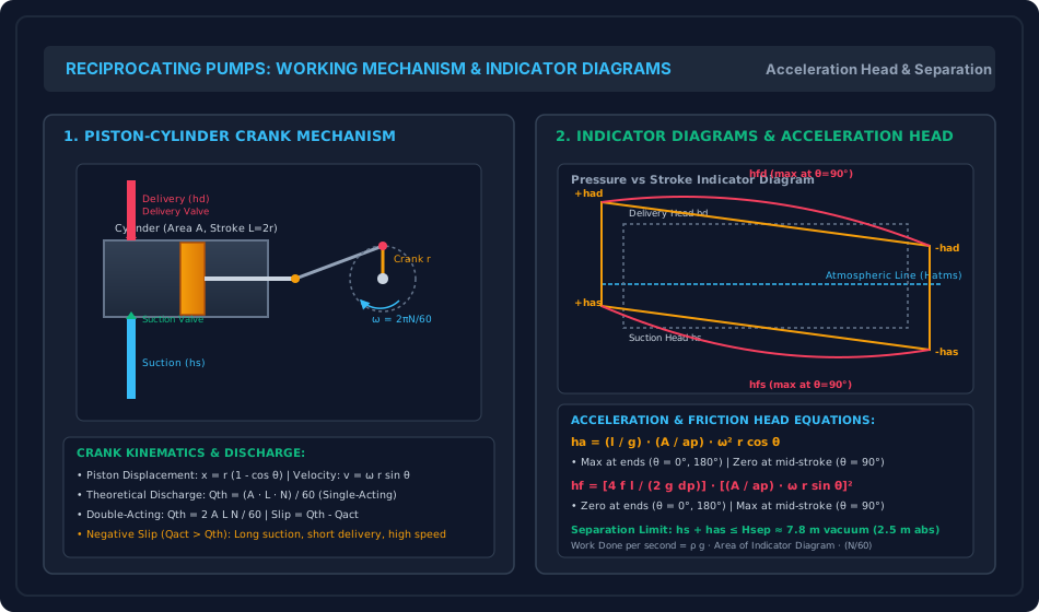
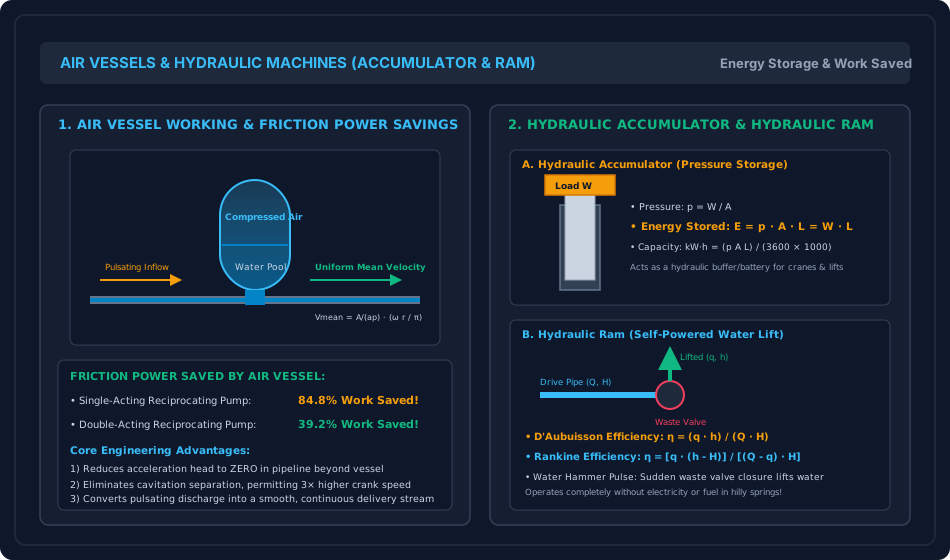
Figure 2: Air Vessel Fluid Dynamics & Hydraulic Auxiliary Machines
This schematic details the fluid exchange mechanism of an air vessel, the mathematical derivation of pipeline mean velocity, and the mechanical layouts of the deadweight hydraulic accumulator and water-hammer hydraulic ram.
6. Comparative Engineering Analysis & Parameter Regimes
| Engineering Attribute | Reciprocating Pump (Single-Acting) | Reciprocating Pump (Double-Acting) | Centrifugal Pump (Rotodynamic) |
|---|---|---|---|
| Discharge Equation | |||
| Flow Uniformity | Highly pulsating (flow during only) | Pulsating (two pulses per rev) | Completely steady and continuous |
| Air Vessel Friction Saving | () | () | Not applicable (flow is already uniform) |
| Operating Speed () | Low () | Low () | High () |
| Priming Need | Self-priming (air displaced by piston) | Self-priming | Mandatory prior to start |
| Maximum Suction Lift | Governed by | Governed by | Governed by |
| Slip Characteristic | Usually ; can be negative | Usually | Not applicable (no mechanical valves) |
7. Worked Numerical Examples (Pre-Calculated & Verified)
Problem 1: Acceleration Head, Slip & Separation Limits
Problem Statement: A single-acting reciprocating pump has a cylinder bore diameter () and a stroke (, crank radius ). The crank rotates at a speed (). Piping dimensions:
- Suction pipe: Length , diameter (), static lift .
- Delivery pipe: Length , diameter (), static head .
- Pipe coefficient of friction (Fanning friction factor): for both pipes (where , equivalent to Darcy-Weisbach friction factor ).
If the actual discharge measured at the outlet is ():
- Calculate theoretical discharge , Slip, percentage slip, and coefficient of discharge .
- Calculate the acceleration heads at the beginning of the suction stroke () and delivery stroke ().
- Calculate maximum friction heads and occurring at mid-stroke ().
- Determine the cylinder pressure heads at the beginning, middle, and end of the suction and delivery strokes.
- Check whether cavitation separation occurs during the suction stroke if the maximum permissible vacuum limit is of water.
- Calculate the maximum crank speed to operate safely without cavitation separation.
Step-by-Step Solution:
1. Discharge & Slip Kinematics: Piston and pipe areas:
Theoretical discharge:
2. Acceleration Heads at Stroke Beginnings (): Crank angular velocity:
Suction acceleration head:
Delivery acceleration head:
3. Maximum Friction Heads at Mid-Stroke (): Maximum pipe velocity:
Suction friction head:
Delivery friction head:
4. Cylinder Pressure Heads Along Stroke:
- Suction Stroke (Vacuum Head):
- At beginning ():
- At middle ():
- At end ():
- Delivery Stroke (Gauge Head Above Atmosphere):
- At beginning ():
- At middle ():
- At end ():
5. Separation Evaluation: Maximum suction vacuum occurs at the beginning of the stroke:
Conclusion: Severe cavitation separation occurs at the start of the suction stroke! The water column breaks, causing heavy knocking and vapor locking.
6. Maximum Allowable Crank Speed (): To prevent separation:
(The pump must be slowed from to , or fitted with a suction air vessel).
Problem 2: Air Vessel Friction Power Savings
Problem Statement: A single-acting reciprocating pump has a cylinder diameter () and a stroke length (, crank radius ). It runs at . The delivery pipe is of length and diameter (), with coefficient of friction (Fanning factor) (Darcy friction factor ).
Calculate:
- Maximum pipe velocity and peak friction head without an air vessel.
- The power dissipated against pipe friction without an air vessel ().
- The uniform mean pipe velocity and friction power loss when an air vessel is fitted ().
- The exact mechanical power saved and the percentage power saved. Compare with a double-acting pump.
Step-by-Step Solution:
1. Delivery Line Kinematics Without Air Vessel:
Maximum delivery velocity (at mid-stroke ):
Peak friction head at mid-stroke:
2. Friction Power Loss Without Air Vessel: Theoretical discharge:
Average friction head over stroke is :
Frictional power lost:
3. Friction Power Loss With Air Vessel: With an air vessel, fluid flows at a uniform steady mean velocity throughout the full revolution:
Uniform constant friction head in the pipe:
Frictional power lost:
4. Power Savings:
Percentage power saved:
(Exact Theoretical Proof: ).
- For a Double-Acting Pump, , yielding:
Problem 3: Hydraulic Accumulator Sizing & Hydraulic Ram Efficiencies
Problem Statement:
- Part A (Hydraulic Accumulator): A deadweight hydraulic accumulator has a vertical ram diameter () and a total lift stroke . The ram is weighted with a ballast load (). Determine the operating hydraulic pressure in and , the potential energy stored in and , and the average power delivered if the accumulator empties in during peak hydraulic crane operation.
- Part B (Hydraulic Ram): A rural hydraulic ram operates under a working supply fall of supplied by a spring with a flow rate (). The ram lifts () to a hill reservoir at elevation above the ram. Compute D'Aubuisson's efficiency and Rankine's efficiency.
Step-by-Step Solution:
Part A: Hydraulic Accumulator Sizing:
- Cross-sectional area of ram:
- Operating hydraulic pressure:
- Total energy capacity stored: In kilowatt-hours:
- Average power output during a rapid discharge stroke:
Part B: Hydraulic Ram Efficiencies:
- Volumetric flow rates:
- Supply head , Delivery head .
- D'Aubuisson's Efficiency ():
- Rankine's Efficiency ():
8. High-Yield Examination Traps & Ambiguities
- Negative Slip Trap:
- Trap: Thinking negative slip is a calculation error.
- Fact: Negative slip occurs physically when (), caused by high crank speeds with long suction pipes and short delivery pipes.
- Acceleration Head vs Friction Head Phase Angle:
- Trap: Adding maximum acceleration head and maximum friction head simultaneously.
- Rule: They are out of phase by ! is maximum at stroke ends () where . is maximum at mid-stroke () where .
- Air Vessel Work Saved Memorization:
- Trap: Inverting single-acting vs double-acting savings.
- Rule: Single-acting pump saves (); double-acting pump saves ().
- Hydraulic Ram Efficiency Confusion:
- Trap: Conflating D'Aubuisson and Rankine efficiency formulas.
- Rule: D'Aubuisson is ; Rankine is . Rankine's efficiency is always strictly lower than D'Aubuisson's.
- Cylinder Separation Location:
- Trap: Assuming separation occurs at mid-stroke due to friction.
- Rule: In reciprocating pumps without air vessels, separation occurs almost exclusively at the beginning of the suction stroke () due to peak acceleration head .
9. Real-World Engineering Applications & Case Studies
- High-Pressure Chemical Injection & Slurry Pipelines: Reciprocating plunger triplex pumps are indispensable for deep well chemical injection in oil and gas production () and cross-country coal slurry pipelines where positive displacement ensures steady metering regardless of pipeline backpressure.
- Offshore Derrick Crane Hydraulic Accumulators: Offshore drilling rigs utilize gas-loaded piston hydraulic accumulators as emergency reserves. If electrical generation fails, the accumulator instantly delivers pressurized fluid to actuate the Blowout Preventer (BOP) rams within milliseconds.
- Hydraulic Rams in Off-Grid Himalayan Villages: Eco-friendly hydraulic rams installed across mountain streams in Uttarakhand and Himachal Pradesh lift drinking water upwards of to hillside communities without consuming a single kilowatt of electricity or liter of fossil fuel.
10. Cross-Disciplinary & Downstream Dependencies
                     ┌──────────────────────────────────────────┐
                     │ FM-06-04: Water Hammer, Wave Celerity,   │
                     │ Joukowsky & Unsteady Pipeline Transients │
                     └────────────────────┬─────────────────────┘
                                          │
                                          ▼
┌────────────────────────────────────────────────────────────────────────────────────────┐
│ FM-08-05: RECIPROCATING PUMPS, AIR VESSELS, ACCUMULATOR & HYDRAULIC RAM MACHINES       │
└───────────┬─────────────────────────────┬───────────────────────────────┬──────────────┘
            │                             │                               │
            ▼                             ▼                               ▼
┌───────────────────────┐   ┌───────────────────────────┐   ┌────────────────────────────┐
│ Pumping Machinery     │   │ High-Pressure Industrial  │   │ Sustainable Rural Water    │
│ Complete Curriculum:  │   │ Hydraulics: Presses,      │   │ Supply: Zero-Energy Ram    │
│ FM-08-01 to FM-08-05  │   │ Heavy Cranes & Intensifiers│  │ Stations in Hilly Terrains │
└───────────────────────┘   └───────────────────────────┘   └────────────────────────────┘
- Upstream: Directly incorporates unsteady fluid acceleration and water hammer mechanics from
FM-06-04. - Curriculum Milestone: Completes the entirety of Chapter 08 (Hydraulic Machinery) and brings Subject 07 (Fluid Mechanics & Hydraulic Machinery) to 100% COMPLETE status!
- Downstream Environmental: Informs water supply engineering on pump station surge suppression, pulsation dampener sizing, and gravity/ram distribution networks.
11. Summary Formula Cheat Sheet & Memory Anchors
- Theoretical Discharge: Single-acting: Double-acting:
- Percentage Slip:
- Acceleration Head:
- Pipe Friction Head:
- Separation Limit (Suction):
- Max Safe Speed:
- Air Vessel Frictional Power Saved:
- Single-acting:
- Double-acting:
- Hydraulic Accumulator:
- Hydraulic Intensifier:
- Hydraulic Ram (D'Aubuisson):
- Hydraulic Ram (Rankine):
12. Comprehensive References & Standard Codes
- Modi, P. N., & Seth, S. M. (2020). Hydraulics and Fluid Mechanics Including Hydraulics Machines (22nd ed.). Standard Book House, New Delhi.
- Rajput, R. K. (2018). A Textbook of Fluid Mechanics and Hydraulic Machines (6th ed.). S. Chand & Company Ltd., New Delhi.
- Bansal, R. K. (2019). A Textbook of Fluid Mechanics and Hydraulic Machines (10th ed.). Laxmi Publications, New Delhi.
- Karassik, I. J., Messina, J. P., Cooper, P., & Heald, C. C. (2008). Pump Handbook (4th ed.). McGraw-Hill Education, New York.
- IS 10572: 1983 — Methods of Test for Positive Displacement Pumps. Bureau of Indian Standards, New Delhi.
- API Standard 674: 2010 — Positive Displacement Pumps — Reciprocating. American Petroleum Institute, Washington, D.C.