Compressibility, Bulk Modulus & Vapor Pressure / Cavitation
In this chapter (4 topics)
On this page
- 1. Topic Metadata & Syllabus Mapping
- 2. Executive Summary & Core Engineering Concepts
- 3. Comprehensive Technical Principles & Mechanics
- 3.1 Compressibility (β) & Bulk Modulus (K)
- 3.2 Thermodynamic Bulk Modulus of Ideal Gases
- 3.3 Speed of Sound (c) and Mach Number (Ma)
- 3.4 Vapor Pressure (pv) and Boiling
- 3.5 Cavitation Mechanics & Asymmetric Bubble Implosion
- 4. Detailed Technical Diagrams & Visual Models
- 4.1 Compressibility, Bulk Modulus & Acoustic Wave Regimes
- 4.2 Vapor Pressure, Cavitation Inception & Micro-Jet Collapse
- 5. Comprehensive Step-by-Step Mathematical Derivations
- 5.1 Derivation of Acoustic Wave Speed (c = √K/ρ)
- 6. Three Fully Worked Unit-Checked Numerical Examples
- Example 1: High-Pressure Volumetric Compression of Water
- Example 2: Speed of Sound & Mach Number in Air vs Water
- Example 3: Siphon Summit Cavitation Head Limit
- 7. Common Engineering Pitfalls & Examination Traps
- 8. Real-World Case Studies & Forensic Analysis
- Forensic Disaster: The 1983 Hoover Dam Spillway Tunnel Cavitation
- 9. Competitive Examination Practice Problems
- Problem 1 (GATE CE - 1 Mark)
- Problem 2 (UPSC ESE Paper-II - 2 Marks)
- Problem 3 (SSC JE - 1 Mark)
- Problem 4 (State PSC AE - 2 Marks)
- Problem 5 (RRB JE - 1 Mark)
- 10. Cross-Subject Synthesis & Advanced Fluid Couplings
- 11. Standard Reference Textbooks & Official Code Specifications
- 12. Comprehensive Summary, Formula Cheatsheet & Key Takeaways
1. Topic Metadata & Syllabus Mapping
| Attribute | Specification |
|---|---|
| Module / Topic ID | FM-01-03 |
| Subject | Fluid Mechanics & Hydraulic Machinery |
| Chapter | 01: Fluid Properties & Rheology |
| Topic Title | Compressibility, Bulk Modulus of Elasticity & Vapor Pressure / Cavitation |
| Primary Reference Standards | IS 4987, Frank M. White (Fluid Mechanics), Fox & McDonald, K.L. Kumar, Modi & Seth (Hydraulics and Fluid Mechanics) |
| Target Competitive Examinations | GATE CE, UPSC ESE (Paper-II), SSC JE, State PSC AE/JE, RRB JE |
| Examination Weightage | GATE (1 to 2 Marks), UPSC ESE (4 to 8 Marks prelims/mains), SSC JE (1 to 2 Marks), State AE/JE (2 to 4 Marks) |
| Prerequisites | FM-01-01 (Fluid Properties), Engineering Thermodynamics (Ideal Gas Laws) |
2. Executive Summary & Core Engineering Concepts
Fluids exhibit two essential thermodynamic and hydraulic properties that govern compressible acoustic waves, water hammer, and localized hydraulic destruction:
-
Compressibility () and Bulk Modulus of Elasticity ():
All real fluids deform elastically under isotropic normal compressive stresses. Compressibility is the fractional change in volume per unit change in pressure (). The Bulk Modulus of Elasticity () represents the direct measure of a fluid's volumetric stiffness. While liquids possess high bulk moduli () and are treated as strictly incompressible in low-speed civil hydraulics, their elasticity becomes critically governing during rapid transient pressure surges (Water Hammer, ) and acoustic sound propagation (). For gases, bulk modulus depends strongly on thermodynamic process conditions: for isothermal processes, and for adiabatic/isentropic processes.- Incompressible Flow Threshold: A flow is considered incompressible whenever the local Mach number satisfies , which guarantees that density variations remain under ().
-
Vapor Pressure () and Cavitation:
Liquids exert a characteristic thermodynamic vapor pressure in equilibrium with their vapor phase. When the local absolute static pressure in a flowing liquid drops to or below the vapor pressure at the prevailing temperature (), localized boiling occurs at ambient temperature, producing microscopic vapor cavities. When these vapor bubbles are swept downstream into higher-pressure zones (), they undergo violent, asymmetric implosion within microseconds (). The resulting liquid micro-jets () deliver localized impact pressures exceeding , causing severe metal fatigue, pitting, structural gouging, intense vibration, and efficiency collapse in hydraulic turbines, pump impellers, siphons, and spillways.
3. Comprehensive Technical Principles & Mechanics
3.1 Compressibility () & Bulk Modulus ()
Consider a mass of fluid occupying volume at pressure and mass density . If the pressure is increased by an infinitesimal increment , the volume decreases by (negative), while the density increases by (positive).
Since mass is conserved ():
The volumetric strain is .
1. Bulk Modulus of Elasticity ():
Defined as the ratio of compressive stress increment () to the resulting volumetric strain ():
- SI Unit: (), , or .
- Dimensions: (identical to pressure and Young's modulus).
2. Coefficient of Compressibility ():
Defined as the reciprocal of the bulk modulus of elasticity:
- SI Unit: ().
- Dimensions: .
3.2 Thermodynamic Bulk Modulus of Ideal Gases
For an ideal gas obeying :
1. Isothermal Compression ():
Under slow compression with complete heat exchange:
Differentiating with respect to :
Substitute into the bulk modulus definition:
The isothermal bulk modulus of an ideal gas equals its absolute pressure.
2. Adiabatic / Isentropic Compression (No heat transfer, ):
Under rapid acoustic pressure wave oscillations:
Differentiating with respect to :
Substitute into bulk modulus:
where is the adiabatic index ( for air).
3.3 Speed of Sound () and Mach Number ()
Acoustic waves are small-amplitude compressive pressure perturbations propagating through a fluid medium:
- In Liquids: .
- In Ideal Gases (Acoustic waves are isentropic): where is the specific gas constant () and is absolute temperature in Kelvin. For air at (): .
Mach Number Flow Classification:
- : Incompressible flow (). Density variations are negligible.
- : Subsonic compressible flow.
- : Transonic flow (mixed subsonic and supersonic zones).
- : Supersonic flow (shock waves present).
- : Hypersonic flow.
3.4 Vapor Pressure () and Boiling
All liquids tend to evaporate into the gaseous phase. In an enclosed container, liquid molecules vaporize until the partial pressure of vapor in the space above reaches an equilibrium value known as the saturation vapor pressure ().
- Vapor pressure is purely a thermodynamic function of temperature: As temperature rises, vapor pressure increases exponentially.
| Liquid | Temperature () | Vapor Pressure () | Equivalent Head ( of Liquid) |
|---|---|---|---|
| Water | abs | ||
| Water | abs | ||
| Water | abs | ||
| Water | (1 atm) | abs | |
| Mercury | () |
Key Exam Fact: Mercury has an extraordinarily low vapor pressure (), which is why it is the premier manometric and barometric liquid (minimal evaporation error in Torricellian vacuums).
3.5 Cavitation Mechanics & Asymmetric Bubble Implosion
Cavitation is the localized vaporization of a flowing liquid caused by dynamic pressure reduction below vapor pressure (), followed by violent bubble collapse upon entering a region of higher pressure.
                    THE 4-STAGE CAVITATION CYCLE

  1. Low Pressure Inception (p <= pv)  --> Microscopic vapor bubbles nucleate
  2. Convective Bubble Transport      --> Bubbles swept into high-pressure recovery zone
  3. Asymmetric Collapse              --> Pressure pushes bubble top; liquid micro-jet forms
  4. Micro-Jet Boundary Impact        --> V_jet > 1000 m/s, p_impact > 1000 MPa --> Pitting
The Cavitation Parameter (Thoma's Number ):
For hydraulic turbomachines (turbines and pumps):
Where:
- = Atmospheric pressure head ( water).
- = Suction lift height (positive when pump is above sump).
- = Frictional head loss in suction line.
- = Vapor pressure head ().
- = Net operating head.
- Criterion: Cavitation occurs whenever (where is the critical cavitation parameter of the runner/impeller).
4. Detailed Technical Diagrams & Visual Models
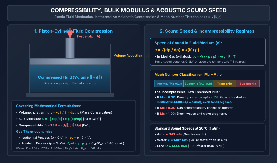
4.1 Compressibility, Bulk Modulus & Acoustic Wave Regimes
The following hand-coded engineering diagram displays the piston-cylinder compression model, volumetric strain relations, thermodynamic comparisons between isothermal and adiabatic compression, and Mach number incompressibility boundaries.
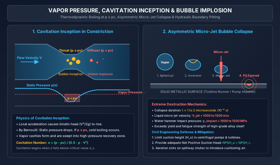
4.2 Vapor Pressure, Cavitation Inception & Micro-Jet Collapse
The following diagram illustrates cavitation inception at a venturi throat or blade constriction, the static pressure profile relative to , and the 4-stage asymmetric bubble implosion mechanism culminating in a micro-jet boundary pit.
5. Comprehensive Step-by-Step Mathematical Derivations
5.1 Derivation of Acoustic Wave Speed ()
Consider a one-dimensional, small-amplitude plane acoustic pressure wave traveling at speed to the right through a stationary fluid of density and pressure . By adopting a reference frame moving with the wave front at velocity :
- Fluid enters the control volume from the right with velocity , pressure , and density .
- Fluid leaves the control volume to the left with velocity , pressure , and density .
-
Continuity Equation (Conservation of Mass):
Neglecting second-order differential product :
-
Momentum Equation (Conservation of Linear Momentum): Net pressure force acting in direction of motion = Rate of momentum flux:
-
Combining Momentum and Continuity: Substitute into the momentum equation:
-
Relation to Bulk Modulus (): Recall definition of bulk modulus: . Therefore:
6. Three Fully Worked Unit-Checked Numerical Examples
Example 1: High-Pressure Volumetric Compression of Water
Problem Statement:
A rigid steel pressure vessel contains of water initially at atmospheric pressure (, density ). A hydraulic ram increases the pressure until the volume of the water decreases by (). The bulk modulus of elasticity of water is .
- Calculate the required pressure increment in .
- Determine the final absolute pressure in .
- Calculate the final compressed mass density of the water and the density change .
Step-by-Step Solution:
Step 1: Pressure Increment Calculation Using the bulk modulus formula:
Substitute numerical values:
Step 2: Final Absolute Pressure
Step 3: Final Density Calculation Mass conservation in closed system:
Example 2: Speed of Sound & Mach Number in Air vs Water
Problem Statement:
Compare the acoustic sound speed and flow compressibility for an underwater projectile and an aircraft both traveling at speed in:
- Dry atmospheric air at (), with adiabatic index and gas constant .
- Fresh water at with bulk modulus and density .
Calculate the Mach number for each case and state whether the flow can be modeled as incompressible.
Step-by-Step Solution:
Step 1: Acoustic Speed in Air For an ideal gas under adiabatic acoustic wave propagation:
Step 2: Acoustic Speed in Water For liquid water:
Observation: Acoustic waves travel over faster in water than in air due to water's massive bulk modulus!
Step 3: Mach Number & Incompressibility Check
- In Air: Since , density changes cannot be neglected; the flow is COMPRESSIBLE subsonic flow.
- In Water: Since , the flow is STRICTLY INCOMPRESSIBLE ().
Example 3: Siphon Summit Cavitation Head Limit
Problem Statement:
A siphon of uniform internal diameter () discharges water from an open storage reservoir at water surface elevation . The length of pipe from the submerged entrance to the summit is . The friction factor of the pipe is , and the entrance loss coefficient is . The operational discharge is .
- Atmospheric pressure: (equivalent head of water absolute).
- Saturation vapor pressure of water at prevailing temperature (): (equivalent head of water absolute).
- To prevent cavitation and air release, the engineer specifies a minimum pressure head margin of above the vapor pressure ().
Calculate the maximum permissible elevation of the siphon summit above the reservoir water level.
Step-by-Step Solution:
Step 1: Flow Velocity and Dynamic Velocity Head Pipe cross-sectional area:
Mean flow velocity:
Velocity head:
Step 2: Head Losses from Reservoir to Summit
- Entrance loss:
- Pipe friction loss:
Total head loss to summit:
Step 3: Minimum Allowable Summit Pressure Head
Step 4: Energy (Bernoulli) Equation from Reservoir to Summit Datum at reservoir water surface (). At reservoir surface: , . At summit: Elevation = , Pressure head = , Velocity = .
Solving for summit elevation :
To keep :
Provide a maximum summit height above the reservoir water surface to ensure cavitation-free siphoning.
7. Common Engineering Pitfalls & Examination Traps
| Pitfall / Exam Trap | Erroneous Concept | Correct Physical & Code Principle |
|---|---|---|
| Trap 1: Confusing Absolute vs Gauge Pressure in Cavitation | Computing negative gauge pressures and mixing them with absolute vapor pressure. | Cavitation occurs when absolute static pressure drops to vapor pressure (). Atmospheric pressure () must ALWAYS be added if gauge heads are used! |
| Trap 2: Using Isothermal Bulk Modulus for Acoustic Waves in Gases | Calculating acoustic wave speed using (Newton's original error). | Acoustic wave oscillations occur at thousands of cycles per second, far too rapid for heat conduction. Gas compression in sound waves is strictly adiabatic/isentropic (), yielding Laplace's correction: . |
| Trap 3: Assuming Cavitation Only Happens in Pumps | Believing cavitation is restricted to rotating impellers. | Cavitation occurs anywhere dynamic velocity creates static pressure drops below : Siphon summits, venturi throats, gate slots, and high-velocity spillways! |
| Trap 4: Neglecting Pipe Friction in Siphons | Computing maximum siphon height merely as . | Frictional losses, entrance losses, and velocity head severely depress summit pressure! In real pipelines, maximum summit lift is typically limited to , never ! |
| Trap 5: Treating Air as Always Compressible | Assuming gases can never be analyzed with the incompressible Bernoulli equation. | When air speeds are below (), density changes are under , and air flows can be analyzed using standard incompressible hydraulics! |
8. Real-World Case Studies & Forensic Analysis
Forensic Disaster: The 1983 Hoover Dam Spillway Tunnel Cavitation
- Context: During the historic 1983 Colorado River flood, Hoover Dam operated its diameter concrete-lined tunnel spillways at discharges exceeding with flow velocities surpassing .
- The Catastrophe: Within hours of peak discharge, deafening vibrations shook the dam abutments. Inspection revealed a cavernous crater gouged into the solid rock tunnel lining: deep, long, and wide, consuming of reinforced concrete and granite bedrock.
- Forensic Failure Analysis:
- A tiny offset of only in a concrete construction joint acted as a ramp, deflecting high-speed flow ().
- Local pressure in the wake of the joint dropped instantaneously to absolute vapor pressure ().
- Billions of cavitation bubbles formed and imploded downstream on the concrete invert.
- The micro-jets fractured the cement paste and aggregate, plucking out reinforcing rebar and initiating catastrophic runaway erosion.
- Engineering Remediation: Installation of Aeration Slots (Aerators) along the spillway invert. By entraining air into the flow, the acoustic sound speed drops and compressibility increases, cushioning bubble collapse and entirely eliminating cavitation pitting!
9. Competitive Examination Practice Problems
Problem 1 (GATE CE - 1 Mark)
The bulk modulus of elasticity of an ideal gas undergoing an isothermal process at absolute pressure is:
- (A)
- (B)
- (C)
- (D)
Correct Answer: (B)
Step-by-Step Explanation:
For an isothermal process, .
.
Problem 2 (UPSC ESE Paper-II - 2 Marks)
Cavitation in a hydraulic turbine is most likely to occur at:
- (A) Runner inlet
- (B) Runner exit / draft tube inlet
- (C) Guide vane passage
- (D) Tail race outlet
Correct Answer: (B)
Step-by-Step Explanation:
At the runner exit and entry to the draft tube, static pressure reaches its absolute minimum in the turbine system as kinetic energy is maximal and head is extracted. If this minimum pressure falls to , cavitation erupts.
Problem 3 (SSC JE - 1 Mark)
Compressibility of a fluid is mathematically defined as:
- (A)
- (B)
- (C)
- (D)
Correct Answer: (B)
Step-by-Step Explanation:
Compressibility is the reciprocal of the bulk modulus of elasticity:
Problem 4 (State PSC AE - 2 Marks)
If a gas travels at velocity where the local speed of sound is , the flow may be assumed to be incompressible when the Mach number is less than:
- (A) 1.00
- (B) 0.80
- (C) 0.50
- (D) 0.30
Correct Answer: (D)
Step-by-Step Explanation:
When , fractional density variation , allowing the fluid to be modeled as incompressible.
Problem 5 (RRB JE - 1 Mark)
Why is mercury universally preferred as a barometric fluid?
- (A) High viscosity
- (B) Extremely low vapor pressure
- (C) High compressibility
- (D) Low surface tension
Correct Answer: (B)
Step-by-Step Explanation:
Mercury has an exceptionally low vapor pressure at ambient temperature (), ensuring that the vacuum formed in the closed top of the barometer tube (Torricelli's vacuum) is virtually free of vapor pressure error.
10. Cross-Subject Synthesis & Advanced Fluid Couplings
                             CROSS-DISCIPLINARY COUPLING

    Fluid Mechanics (FM-01-03)
    - Bulk Modulus K & Speed of Sound c = sqrt(K/rho)
    - Vapor Pressure pv & Cavitation Inception
                         |
                         v
    Hydraulic Engineering & Turbomachinery (FM-08)
    - Net Positive Suction Head (NPSH_a >= NPSH_r) in Centrifugal Pumps
    - Thoma's Cavitation Factor sigma = (H_atm - H_s - h_f - H_v) / H
                         |
                         v
    Water Resources Engineering & Hydraulic Structures (SUB-08)
    - Dam Spillway Aeration Chutes (Mitigating cavitation pitting via air entrainment)
    - Transient Water Hammer in Penstocks (Joukowsky's equation Delta p = rho * c * Delta V)
11. Standard Reference Textbooks & Official Code Specifications
- Frank M. White: Fluid Mechanics, 8th Edition, McGraw-Hill, Chapter 1: Introduction and Compressibility of Fluids.
- P.N. Modi & S.M. Seth: Hydraulics and Fluid Mechanics Including Hydraulic Machines, Standard Book House, New Delhi, Chapter 1: Compressibility and Vapor Pressure.
- K.L. Kumar: Engineering Fluid Mechanics, S. Chand Publishing, New Delhi, Chapter 1: Fluids and Their Properties.
- IS 4987: Recommendations for Design and Installation of Flow Measurement Devices, BIS, New Delhi.
- C.S. Rao: Cavitation in Hydraulic Structures and Machinery, Oxford & IBH Publishing.
12. Comprehensive Summary, Formula Cheatsheet & Key Takeaways
===================================================================================================
                       COMPRESSIBILITY, BULK MODULUS & CAVITATION CHEATSHEET
===================================================================================================
1. Bulk Modulus (K) & Compressibility (beta):
   - Bulk Modulus:        K = -V * (dp/dV) = rho * (dp/drho)      [Pa = N/m²], [M L⁻¹ T⁻²]
   - Compressibility:     beta = 1 / K = -(1/V) * (dV/dp)        [Pa⁻¹], [M⁻¹ L T²]
   - Water @ 20°C:        K ≈ 2.10 × 10⁹ Pa (2.10 GPa)

2. Thermodynamic Gas Bulk Modulus:
   - Isothermal (T=const):K_iso = p                              (beta = 1/p)
   - Adiabatic (s=const): K_ad = gamma * p                      (beta = 1 / [gamma * p])
     (gamma = Cp/Cv ≈ 1.40 for air)

3. Acoustic Sound Speed (c) & Mach Number:
   - General Medium:      c = sqrt(dp/drho) = sqrt(K / rho)
   - Ideal Gas:           c = sqrt(gamma * R * T)                (T in Kelvin!)
   - Incompressible Rule: Ma = V / c < 0.30                      (Density variation < 5%)

4. Vapor Pressure (pv) & Boiling:
   - Water @ 20°C:        pv = 2.34 kPa ≈ 0.24 m of water absolute
   - Water @ 100°C:       pv = 101.3 kPa = 1 atm (Standard boiling point)
   - Mercury @ 20°C:      pv ≈ 0.16 Pa (Extremely low => Ideal barometric fluid)

5. Cavitation Mechanics:
   - Inception:           Occurs whenever local p_abs <= pv
   - Micro-Jet Velocity:  V_jet > 1000 m/s (Asymmetric collapse)
   - Impact Pressure:     p_impact > 1000 MPa (Causes severe metal pitting erosion)
   - Thoma's Number:      sigma = (p - pv) / (0.5 * rho * V²)
   - Siphon Summit Limit: z_s,max = H_atm - H_v,min - (V²/2g) - h_losses
===================================================================================================