Reaction Turbines (Francis & Kaplan Turbines): Inward Radial Flow, Axial Propeller, Draft Tube Theory, Specific Speed & Cavitation
In this chapter (5 topics)
On this page
- 1. Module Overview & Pedagogical Scope
- 2. Official Examination Syllabus Mapping
- 3. Fundamental Physical Principles & Governing Assumptions
- 4. Mathematical Derivations & Rigorous Proofs
- Sub-derivation A: Euler's Turbine Head & Degree of Reaction (R)
- Sub-derivation B: Francis Turbine Kinematics & Velocity Triangles
- Sub-derivation C: Kaplan & Propeller Axial Flow Runners
- Sub-derivation D: Draft Tube Theory & Pressure Recovery
- Sub-derivation E: Cavitation Mechanics & Thoma's Cavitation Factor (σ)
- 5. Technical Diagrams & Interactive Architectural Schematics
- Figure 1: Francis Inward Mixed Flow & Kaplan Axial Runner Hydrodynamics
- Figure 2: Draft Tube Pressure Recovery & Cavitation Mechanics (Thoma σ)
- 6. Comparative Engineering Analysis & Parameter Regimes
- 7. Worked Numerical Examples (Pre-Calculated & Verified)
- Problem 1: Francis Turbine Velocity Triangles & Runner Design
- Problem 2: Kaplan Turbine Sizing & Specific Speed Analysis
- Problem 3: Draft Tube Pressure Recovery & Thoma's Cavitation Setting
- 8. High-Yield Examination Traps & Ambiguities
- 9. Real-World Engineering Applications & Case Studies
- 10. Cross-Disciplinary & Downstream Dependencies
- 11. Summary Formula Cheat Sheet & Memory Anchors
- 12. Comprehensive References & Standard Codes
1. Module Overview & Pedagogical Scope
Reaction hydraulic turbines operate on a fundamentally distinct physical regime compared to impulse machines. Whereas a Pelton turbine extracts energy solely from the kinetic head of an atmospheric free jet, a reaction turbine operates completely submerged under positive fluid pressure throughout a closed, pressurized conduit system. As water traverses the stationary guide apparatus and the rotating runner, only a fraction of the available total head is converted into kinetic energy before entering the runner; the remaining fraction enters the runner as pressure head.
Inside the runner passages, the fluid undergoes a continuous pressure drop from inlet to outlet (). The accelerating relative flow across the contoured runner blades produces an aerofoil/hydrodynamic reaction force that drives the shaft.
                   Reaction Turbine Energy Conversion Path
    ┌─────────────────────────┐         High Pressure Head H
    │ Penstock / Forebay Dam  │────────────────────────────────────────┐
    └─────────────────────────┘                                        │
                                                                       ▼
    ┌─────────────────────────┐   Kinetic & Pressure Energy    ┌───────────────┐
    │ Movable Wicket Gates    │◄───────────────────────────────┤ Spiral Casing │
    │ Guide Vane Angle α1     │  Imparts Whirl Velocity Vw1    │ Scroll Volute │
    └───────────┬─────────────┘                                └───────────────┘
                │
                ▼
    ┌─────────────────────────┐   Euler Work W = ṁ(Vw1·u1)     ┌───────────────┐
    │ Rotating Runner Wheel   ├───────────────────────────────►│ AC Generator  │
    │ Francis / Kaplan Blades │   Continuous Pressure Drop     └───────────────┘
    └───────────┬─────────────┘
                │ Low Pressure & High Kinetic Exit Velocity V2
                ▼
    ┌─────────────────────────┐   Kinetic Energy Recovery (V2² - V3²)/2g
    │ Diffusing Draft Tube    │────────────────────────────────────────┐
    │ Sub-atmospheric Suction │                                        │
    └─────────────────────────┘                                        ▼
                                                               ┌───────────────┐
                                                               │ Tailrace Pool │
                                                               └───────────────┘
This master technical module establishes the comprehensive fluid dynamics of the two paramount reaction turbines in modern hydroelectric engineering:
- The Inward-Flow Reaction Turbine (Francis Turbine): Medium-head () mixed-flow runner featuring spiral scroll cases, stay rings, adjustable wicket gates, and radial/axial discharge.
- The Axial-Flow Reaction Turbine (Kaplan & Propeller Turbines): Low-head (), high-discharge machines featuring twisted aerofoil blades with dual servomotor governing (Kaplan) yielding an exceptionally flat part-load efficiency curve.
- The Degree of Reaction (): The thermodynamic and hydrodynamic metric quantifying the proportion of static pressure drop occurring inside the runner.
- Draft Tube Fluid Mechanics: Conical diffusers, elbow tubes, and Moody spreading bell-mouths; recovery of exit kinetic energy ; creation of sub-atmospheric suction head; and setting elevation .
- Cavitation Inception & Thoma's Cavitation Factor (): Bubble nucleation at localized low-pressure zones (), microjet implosion fatigue, pitting failure, and calculation of critical turbine setting height ().
- Specific Speed () & Unit Quantities: Scaling criteria and selection guidelines across impulse, reaction, and axial hydraulic machinery.
2. Official Examination Syllabus Mapping
Website note: this mapping is from the author’s notes. It has not been checked against the official notification for each examination; confirm the current syllabus with the examining body.
| Examination Body | Syllabus Code & Topics | Core Weightage & Target Focus |
|---|---|---|
| GATE (Civil Engineering) | Water Resources: Hydraulic Machinery — Reaction turbines; Inward radial flow and mixed flow Francis turbines; Axial flow Kaplan turbines; Velocity triangles; Work done and hydraulic efficiency; Degree of reaction; Draft tube theory and efficiency; Cavitation and Thoma's parameter; Specific speed. | Very High (1 to 2 questions yearly): Calculation of runner blade angles (), draft tube vacuum pressure, setting height , and specific speed classification. |
| UPSC ESE (Prelims & Mains) | Paper-II: Fluid Mechanics and Hydraulic Machines — Principles of reaction turbines, Francis and Kaplan turbines, velocity triangles at inlet and exit, Euler head, degree of reaction, draft tube types and efficiency, cavitation inception, Thoma's cavitation factor, selection criteria. | Core Subject: Derivations of degree of reaction , draft tube pressure equation, Thoma factor , and multi-part numerical design of Francis runners. |
| SSC JE & RRB JE | Civil / Mechanical Engineering — Working of reaction turbines, function of draft tube, reason for draft tube submerged exit, definition of cavitation, specific speed ranges. | Direct / Objective: Velocity triangle relations for radial exit (), values (Francis , Kaplan ), limits. |
| State AE / JE (All States) | Fluid Mechanics & Machinery — Francis runner blade angles, Kaplan flow ratio and discharge, draft tube efficiency formula, net positive suction head in turbines. | Objective & Numerical: Numerical evaluation of blade angles, draft tube recovery, and critical cavitation height. |
3. Fundamental Physical Principles & Governing Assumptions
- Closed Conduit Operation: The fluid completely fills all casing passages, guide channels, runner blade passages, and the draft tube. The flow is enclosed under continuous hydraulic pressure without free surfaces.
- Euler Turbine Momentum Balance: The mechanical power transferred from fluid to runner is governed by the angular momentum exchange across inlet (radius ) and outlet (radius ):
- Condition for Maximum Hydraulic Efficiency (Radial Exit): For optimal hydraulic energy extraction, the fluid should leave the runner with zero whirl velocity (), discharging in a purely radial (or axial) direction perpendicular to blade motion (). In this state, kinetic energy rejected to the tailrace is minimized:
- Draft Tube Submergence: The downstream exit of the draft tube must remain completely submerged below the minimum tailrace water surface at all times to maintain a continuous, airtight fluid column, preventing atmospheric air ingress that would destroy the suction vacuum.
- Cavitation Threshold: Cavitation nucleates spontaneously at any point on the runner blades or draft tube inlet where the local absolute static pressure drops to or below the saturation vapor pressure of water at the operating temperature:
4. Mathematical Derivations & Rigorous Proofs
========================================================================================
REACTION TURBINE DERIVATION TAXONOMY
========================================================================================
Euler Energy Transfer: H_euler = (Vw1 u1 - Vw2 u2) / g
       │
       ├─────────────────────────────────────────┐
       ▼                                         ▼
DEGREE OF REACTION (R)                    RADIAL DISCHARGE DESIGN (Vw2 = 0)
R = Static Head Drop / Total Stage Head    H_euler = (Vw1 u1) / g
R = 1 - (V1² - V2²) / (2g H_euler)        ηh = (Vw1 u1) / (g H)
       │                                         │
       ├─► Francis Turbine: R ≈ 0.50             ├─► Inlet Triangle: tan α1 = Vf1 / Vw1
       └─► Kaplan Turbine:  R ≈ 0.70 - 0.85      │   tan(180°-θ1) = Vf1 / (u1 - Vw1)
                                                 └─► Outlet Triangle: tan β2 = Vf2 / u2
       ┌─────────────────────────────────────────┘
       ▼
DRAFT TUBE PRESSURE RECOVERY
p2/ρg = pa/ρg - zs - [(V2² - V3²)/2g - hf]
       │
       ▼
CAVITATION & THOMA PARAMETER
σ = (Ha - Hv - zs) / H > σc
Maximum Permissible Setting: zs,max = Ha - Hv - σc · H
========================================================================================
Sub-derivation A: Euler's Turbine Head & Degree of Reaction ()
Consider steady, incompressible flow through a reaction turbine runner. Applying the generalized energy equation across runner inlet (point 1) and runner outlet (point 2):
Neglecting internal runner losses () and elevation difference ():
From the kinematic cosine rule applied to the inlet and outlet velocity triangles:
Substituting into Euler's equation :
Equating the two expressions for reveals the static pressure head drop across the runner:
Definition of Degree of Reaction ():
The Degree of Reaction () is defined as the ratio of the static pressure head drop inside the runner to the total energy head extracted by the runner stage:
Alternatively, expressing in terms of absolute kinetic heads:
Physical Significance of Degree of Reaction:
- (Impulse Turbine / Pelton Wheel): . No pressure drop occurs in the runner; the entire energy transfer is kinetic ().
- (50% Reaction / Parson's Stage in Francis): Exactly half the head is converted to kinetic energy in the guide vanes, and the remaining half is extracted via static pressure drop within the runner.
- (Kaplan Axial Turbine): The machine is heavily reaction-dominated; the runner operates primarily as a lifting aerofoil foil in a pressurized stream.
Sub-derivation B: Francis Turbine Kinematics & Velocity Triangles
In a modern Francis turbine, water enters from the spiral casing through fixed stay vanes and adjustable wicket gates (inlet guide angle ), flows inward radially across the runner outer periphery (diameter , width ), and discharges axially into the draft tube (inner diameter , width ).
1. Volumetric Discharge Continuity:
Accounting for the circumferential vane blockage factor (, where vanes occupy of perimeter):
In standard designs, the flow velocity is maintained approximately constant through the runner:
(where is the flow ratio, typically .)
2. Inlet Triangle Relations:
Let be the peripheral blade velocity at inlet ().
- Absolute inlet velocity:
- Inlet whirl velocity:
In virtually all medium and high-speed Francis turbines, . Therefore, the relative velocity vector leans backwards against the direction of blade motion.
The runner blade inlet angle (measured from the backward direction of motion) is:
(Measured from the forward tangent of motion, the blade angle is the obtuse angle .)
3. Radial Outlet Triangle (Optimal Design):
To maximize energy extraction, the runner is designed for radial discharge at outlet:
The blade velocity at outlet radius is:
The exit blade angle is governed by the right-angled outlet triangle:
4. Euler Head & Hydraulic Efficiency:
Under radial exit ():
Sub-derivation C: Kaplan & Propeller Axial Flow Runners
In a Kaplan turbine, water flows through a spiral casing and passes through radial wicket gates before entering an open hub region where curved guide vanes deflect the flow into a purely axial direction parallel to the vertical rotor shaft.
Let:
- : Outer tip diameter of the runner casing.
- : Hub (boss) diameter.
- Diameter ratio: .
1. Annular Discharge Equation:
The flow area through the runner is the annular cross-section between hub and casing tip:
(In an axial machine, the flow velocity is strictly uniform across the entire annular span from hub to tip: .)
Flow ratio: .
Speed ratio (based on tip diameter): .
2. Spanwise Variation of Blade Speed & Free Vortex Twist:
The peripheral blade velocity increases linearly from hub to tip:
To ensure uniform work extraction per unit mass across the entire blade length (), the fluid must satisfy the free vortex circulation condition:
Consequently:
- At the hub ( small): is small, while is large.
- At the tip ( large): is large, while is small.
To match the local relative velocity vector without shock, Kaplan runner blades must be spatially twisted:
- The blade inlet angle is steep (large) at the hub and flat (shallow) at the tip:
- The blade outlet angle is steep at the hub and very flat at the tip:
Sub-derivation D: Draft Tube Theory & Pressure Recovery
In reaction turbines, the pressure at runner exit is substantially below atmospheric pressure. Furthermore, because reaction runners operate at high specific speeds, the kinetic energy remaining in the exit stream () represents of total head in a Francis turbine and up to of total head in a Kaplan turbine. If discharged directly into the tailrace, this kinetic energy would be completely wasted.
A Draft Tube is an airtight, gradually diverging conduit connected from the runner outlet (point 2) to the tailrace pool (point 3). It performs two critical hydraulic functions:
- Kinetic Energy Recovery: By expanding the flow area (), it decelerates the fluid from high exit velocity to negligible tailrace discharge velocity , converting dynamic head into static pressure head.
- Suction Setting Elevation (): It allows the heavy turbine machinery to be placed safely above the tailrace flood level at elevation without losing any effective head.
Mathematical Derivation of Draft Tube Pressure Head:
Let:
- Point 2: Runner exit / draft tube inlet (elevation above tailrace).
- Point 3: Draft tube exit / tailrace surface (elevation ).
- : Atmospheric pressure.
- : Head loss due to wall friction and eddy turbulence inside the draft tube.
Applying Bernoulli's equation between point 2 and point 3:
Since point 3 discharges into the open tailrace, static pressure is atmospheric: . Rearranging for the absolute static pressure head at the runner exit:
Vacuum pressure head at runner exit (gauge suction):
Draft Tube Efficiency ():
- Straight conical diffusers: (semi-divergent cone angle to prevent boundary layer stall).
- Elbow draft tubes with rectangular exit: .
Sub-derivation E: Cavitation Mechanics & Thoma's Cavitation Factor ()
1. Cavitation Inception:
Cavitation occurs when the absolute pressure at the runner exit drops to the saturation vapor pressure of water ().
From the draft tube pressure equation:
If is set too high, drops to . Tiny microscopic dissolved air pockets expand explosively into vapor bubbles. As these vapor cavities travel downstream into regions of higher pressure, they implode violently in nanoseconds, producing localized microjets with impact pressures exceeding . Over millions of cycles, this mechanical hammering causes severe surface pitting, erosion, acoustic screeching, and catastrophic blade structural failure.
2. Thoma's Cavitation Factor ():
Professor Dieter Thoma (1924) formulated the non-dimensional cavitation parameter :
(where , at , and is the net effective turbine head).
3. Maximum Permissible Setting Elevation ():
Every turbine geometry possesses an experimental critical cavitation factor determined by model testing. For safe, cavitation-free operation:
Equating defines the maximum allowable installation height of the runner above tailrace level:
Important Civil Engineering Setting Rule: If evaluates to a negative number (), the runner must be set below the tailrace level (negative setting / submerged powerhouse excavation). This is exceptionally common in high-capacity Kaplan turbines () where the runner is positioned below the tailrace water level!
Empirical correlations for critical Thoma factor:
- For Francis turbines:
- For Kaplan turbines:
5. Technical Diagrams & Interactive Architectural Schematics
Figure 1: Francis Inward Mixed Flow & Kaplan Axial Runner Hydrodynamics
This schematic illustrates the spiral volute casing, stay vanes, wicket gates, and radial-exit velocity triangles for a Francis runner, alongside the axial-flow Kaplan hub mechanism, twisted blade span, and comparative part-load efficiency curves.
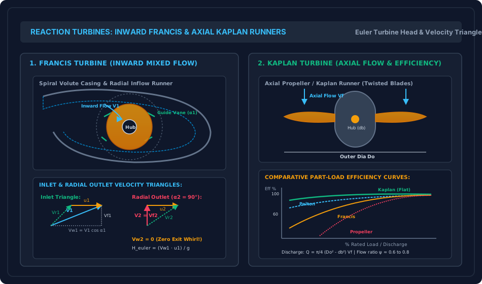
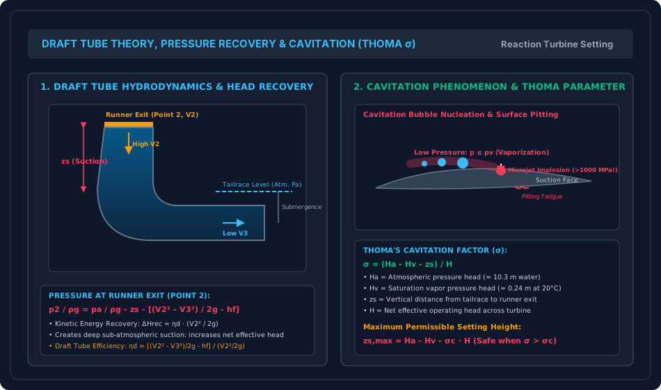
Figure 2: Draft Tube Pressure Recovery & Cavitation Mechanics (Thoma )
This schematic details the fluid dynamics of an elbow draft tube, the kinetic energy recovery conversion line, the generation of sub-atmospheric suction, the microjet implosion cycle of cavitation bubbles, and the geometric definition of Thoma's setting height .
6. Comparative Engineering Analysis & Parameter Regimes
| Metric / Parameter | Pelton Turbine (Impulse) | Francis Turbine (Reaction) | Kaplan Turbine (Reaction) |
|---|---|---|---|
| Head Range () | High () | Medium () | Low () |
| Discharge Range () | Low | Medium | Exceptionally Large |
| Flow Direction | Tangential along pitch line | Inward mixed (radial to axial) | Purely axial (parallel to shaft) |
| Specific Speed (, SI: rpm, kW, m) | (Single Jet) (Multi-Jet) |
||
| Degree of Reaction () | |||
| Speed Ratio () | (Based on tip) | ||
| Flow Ratio () | N/A () | ||
| Runner Setting | Strictly above tailrace () | Above or below tailrace () | Usually set below tailrace () |
| Draft Tube Requirement | None (Destroyed by draft tube) | Mandatory () | Mandatory () |
| Governing Regulation | Spear needle + Jet deflector | Movable wicket gates | Dual-regulation: Synchronized wicket gates + adjustable runner blades |
7. Worked Numerical Examples (Pre-Calculated & Verified)
Problem 1: Francis Turbine Velocity Triangles & Runner Design
Problem Statement: An inward flow Francis reaction turbine operates under a net effective head of at a rotational speed of . The runner outer diameter at inlet is , and the blade width at inlet is . Water enters the runner from the guide vanes at an angle to the tangential direction. The radial velocity of flow is uniform through the runner: .
The discharge is purely radial at outlet (). The runner inner diameter at exit is . Vanes occupy of the circumferential entrance area (). Hydraulic efficiency is , and mechanical efficiency is .
Calculate:
- Tangential runner blade velocity at inlet and inlet whirl velocity .
- Absolute inlet velocity and runner blade inlet angle .
- Total volumetric discharge in and .
- Overall efficiency and shaft power in kW and MW.
- Runner blade velocity at outlet and blade exit angle .
- Euler head and the Degree of Reaction .
Step-by-Step Solution:
1. Inlet Kinematic Velocities: Tangential blade velocity at inlet:
From the inlet triangle, since and :
Absolute approach velocity:
2. Blade Inlet Angle (): Notice that . The relative velocity vector leans backwards against blade motion:
(Measured from the forward tangential direction of motion, the blade angle is the obtuse angle .)
3. Volumetric Discharge (): Net circumferential flow area:
4. Power Developed: Overall plant efficiency:
Shaft power delivered:
5. Outlet Triangle & Blade Exit Angle (): Exit blade speed at diameter :
Since discharge is radial ():
6. Euler Head & Degree of Reaction (): Euler head:
Check: (exact ).
Degree of Reaction ():
Since discharge is radial, absolute exit velocity is .
(Confirms classic 50% reaction design!).
Problem 2: Kaplan Turbine Sizing & Specific Speed Analysis
Problem Statement: A low-head river barrage installation utilizes a Kaplan turbine operating under a net head . The turbine develops a shaft power () at a synchronous speed .
Operating parameters:
- Overall efficiency:
- Hydraulic efficiency:
- Speed ratio based on outer tip diameter:
- Flow ratio:
- Boss / hub diameter ratio:
Calculate:
- The spouting velocity , axial flow velocity , and total volumetric discharge .
- The outer tip diameter and hub diameter .
- The specific speed in standard SI metric units ().
- Tangential blade speed at the hub () and at the outer tip ().
- The runner blade angles at inlet () and outlet () at the hub and tip assuming radial exit ().
Step-by-Step Solution:
1. Kinematic Velocities & Total Discharge:
Axial flow velocity (constant across entire annular span):
Total volumetric discharge from shaft power:
2. Runner Dimensions ( and ): Annular area continuity:
Hub diameter:
3. Specific Speed ():
4. Tangential Blade Velocities: At the outer tip ():
At the hub ():
5. Blade Angles at Hub and Tip (Euler Work Across Span): Euler head:
Under radial discharge (): .
-
At the Hub ():
Notice that . The inlet whirl exceeds blade speed!
Outlet blade angle:
-
At the Outer Tip ():
Here :
Outlet blade angle:
Observation: The blade is twisted from at the hub down to at the tip, confirming rigorous free-vortex 3D aerofoil design!
Problem 3: Draft Tube Pressure Recovery & Thoma's Cavitation Setting
Problem Statement: A Francis turbine operating under a net head of is equipped with a conical draft tube of circular cross-section. The draft tube has an inlet diameter and an exit diameter . The runner is installed at an elevation above the tailrace surface. The total discharge through the unit is .
Hydraulic friction and eddy dissipation losses in the draft tube are given by . Ambient conditions:
- Atmospheric pressure head: of water
- Saturation vapor pressure head: of water
- Critical Thoma cavitation factor for this runner:
Calculate:
- Flow velocities and at the draft tube inlet and outlet.
- Net pressure head recovery and draft tube efficiency .
- The absolute pressure head and vacuum pressure head at the runner exit.
- The operating Thoma cavitation factor under these conditions.
- The maximum permissible setting height above the tailrace to guarantee cavitation-free operation, and the available safety margin.
Step-by-Step Solution:
1. Draft Tube Velocities: Inlet cross-sectional area:
Outlet cross-sectional area:
2. Head Recovery & Efficiency: Head loss in draft tube:
Net pressure head recovered by the draft tube:
Draft tube efficiency:
3. Static Pressure at Runner Exit (Point 2): From Bernoulli's equation across the draft tube:
In kilopascals:
Vacuum pressure head (suction relative to atmosphere):
4. Operating Thoma Cavitation Factor ():
5. Maximum Permissible Setting Height () & Safety: To prevent cavitation, the actual must exceed the critical value :
Safety margin:
Since the actual runner elevation is strictly less than (and operating ), the installation is safe against cavitation by a vertical margin of .
8. High-Yield Examination Traps & Ambiguities
- Draft Tube Pressure Recovery Sign Trap:
- Trap: Adding the draft tube pressure recovery to atmospheric head instead of subtracting it when computing absolute pressure at runner exit.
- Rule: The draft tube creates a vacuum suction that pulls water out of the runner: Both and serve to reduce the absolute static pressure at point 2.
- Radial Exit Confusion ():
- Trap: Assuming that radial exit means the blade angle is .
- Rule: Radial discharge means the absolute fluid velocity vector is radial (). The blade angle is NOT ; it is given by .
- Negative Setting Height for Kaplan Turbines:
- Trap: Thinking a calculated negative setting height represents an arithmetic error.
- Physical Reality: In high-capacity Kaplan turbines operating under low heads with high flow velocities, . Therefore, is routinely negative, mandating that the runner be positioned below the tailrace pool level (deep subterranean powerhouse excavation).
- Specific Speed Metric Units:
- Trap: Confounding turbine specific speed with pump specific speed.
- Rule:
- Turbine Specific Speed: (where is in or , in ).
- Pump Specific Speed: (where is in , in ).
- Fixed Propeller vs Kaplan Part-Load Curve:
- Trap: Assuming propeller turbines have flat efficiency curves.
- Clarification: A propeller turbine has fixed blades; its efficiency plummets drastically as soon as flow deviates from design point. Only the Kaplan turbine (with its dual-regulated variable pitch blades) achieves an exceptionally flat efficiency curve across load.
9. Real-World Engineering Applications & Case Studies
- Three Gorges Dam (China) & Tehri Dam (India): The Three Gorges powerhouse incorporates 32 massive Francis turbine units, each developing under a design head of with runner diameters of . Tehri Dam (Uttarakhand) houses four reversible Francis pump-turbines operating under a net head of .
- Itaipu Hydroelectric Project (Brazil/Paraguay): Generating , Itaipu employs twenty Francis units with runner diameters of weighing over each, operating under head.
- Prakasam Barrage & Kosi Hydel Station (Low-Head Kaplan): The Kosi and Prakasam low-head run-of-river installations utilize bulb-type and vertical Kaplan turbines operating under heads as low as . Because of the severe cavitation risk at high flow ratios, the runners are set below the downstream riverbed.
10. Cross-Disciplinary & Downstream Dependencies
                     ┌──────────────────────────────────────────┐
                     │ FM-08-01: Impact of Free Jets &          │
                     │ Euler Turbine Momentum Exchange          │
                     └────────────────────┬─────────────────────┘
                                          │
                                          ▼
┌────────────────────────────────────────────────────────────────────────────────────────┐
│ FM-08-03: REACTION TURBINES (FRANCIS, KAPLAN, DRAFT TUBE RECOVERY, THOMA CAVITATION)  │
└───────────┬─────────────────────────────┬───────────────────────────────┬──────────────┘
            │                             │                               │
            ▼                             ▼                               ▼
┌───────────────────────┐   ┌───────────────────────────┐   ┌────────────────────────────┐
│ FM-08-04: Centrifugal │   │ Structural & Foundation:  │   │ Environmental Hydrology:   │
│ Pumps (Reverse Euler, │   │ Powerhouse Substructure,  │   │ Fish-Friendly Kaplan       │
│ Manometric Head, NPSH)│   │ Deep Draft Tube Caissons  │   │ Runners & River Ecology    │
└───────────────────────┘   └───────────────────────────┘   └────────────────────────────┘
- Upstream: Directly implements Euler's head formulation and velocity triangle kinematics from
FM-08-01. - Downstream Pumps: Establishes the hydrodynamic foundation for centrifugal pumps (
FM-08-04), where the energy transfer is reversed (fluid absorbs mechanical energy from impeller, governed by Net Positive Suction Head NPSH analogous to Thoma ). - Downstream Civil Engineering: Determines substructure powerhouse excavation depth, draft tube liner structural design, and tailrace channel grading.
11. Summary Formula Cheat Sheet & Memory Anchors
- Euler Turbine Head:
- Degree of Reaction:
- Francis Discharge:
- Kaplan Discharge:
- Draft Tube Exit Pressure:
- Draft Tube Efficiency:
- Thoma's Cavitation Factor:
- Max Safe Setting Height:
- Turbine Specific Speed (SI):
- Pelton (single jet):
- Pelton (multi-jet):
- Francis:
- Kaplan:
- Unit Quantities:
12. Comprehensive References & Standard Codes
- Modi, P. N., & Seth, S. M. (2020). Hydraulics and Fluid Mechanics Including Hydraulics Machines (22nd ed.). Standard Book House, New Delhi.
- Dixon, S. L., & Hall, C. A. (2014). Fluid Mechanics and Thermodynamics of Turbomachinery (7th ed.). Butterworth-Heinemann, Oxford.
- Bansal, R. K. (2019). A Textbook of Fluid Mechanics and Hydraulic Machines (10th ed.). Laxmi Publications, New Delhi.
- IS 12800 (Part 1): 1993 — Guidelines for Selection of Hydraulic Turbines for Use in Hydroelectric Power Stations: Part 1 Selection of Turbine Type. Bureau of Indian Standards, New Delhi.
- IS 12800 (Part 3): 1991 — Guidelines for Selection of Hydraulic Turbines: Part 3 Small Hydroelectric Power Stations. Bureau of Indian Standards, New Delhi.
- IEC 60041: 1991 — Field acceptance tests to determine the hydraulic performance of hydraulic turbines, storage pumps and pump-turbines. International Electrotechnical Commission, Geneva.