Hydrostatic Forces on Submerged Plane & Curved Surfaces
In this chapter (4 topics)
On this page
- 1. Topic Metadata & Syllabus Mapping
- 2. Executive Summary & Core Engineering Concepts
- 3. Hydrostatic Forces on Submerged Plane Surfaces
- 3.1 Total Hydrostatic Force Derivation
- 4. Center of Pressure (CP) Analytical Derivation
- 4.1 Derivation Along the Inclined Plane (ycp)
- 4.2 Vertical Depth of Center of Pressure (hcp)
- 4.3 Key Geometric and Physical Properties
- 4.4 Geometric Properties & Center of Pressure for Standard Vertical Shapes
- 5. Hydrostatic Forces on Submerged Curved Surfaces
- 5.1 Horizontal Component (Fx)
- 5.2 Vertical Component (Fy)
- 5.3 Resultant Force Magnitude & Direction
- 5.4 The Radial (Tainter) Gate Principle
- 6. Complete Mathematical Formulations & Derivations Summary
- 7. Visual Architectural Diagrams
- Diagram 1: Submerged Plane Surfaces & Center of Pressure Derivation
- Diagram 2: Hydrostatic Thrust on Submerged Curved Surfaces & Radial Gates
- 8. Worked Numerical Problems
- Problem 1: Inclined Sluice Gate Equilibrium & Minimum Hoist Force (GATE / ESE Standard)
- Problem 2: Center of Pressure Comparison for Vertical Triangular Plates (ESE / SSC JE Standard)
- Problem 3: Resultant Hydrostatic Thrust on a Radial Tainter Gate (GATE Standard)
- 9. Common Traps, Fallacies & Edge Cases
- Trap 1: Confusing Inclined Distance with Vertical Depth
- Trap 2: Locating the Center of Pressure Above or At the Centroid
- Trap 3: Neglecting Virtual Fluid Volume on Underside of Curved Gates
- Trap 4: Assuming Tainter Gates Require Huge Lifting Power
- Trap 5: Pressure Prism on Non-Rectangular Plates
- 10. Multi-Exam Multi-Choice & Conventional Practice Set
- Q1. GATE CE (1 Mark) — Center of Pressure Depth Ratio
- Q2. UPSC ESE (Paper-II) — Hydrostatic Force on Inclined vs Vertical Surface
- Q3. SSC JE — Vertical Triangle Center of Pressure
- Q4. State AE — Horizontal Component of Curved Surface
- Q5. RRB JE — Radial Gate Trunnion Moment
- 11. Cross-Subject Synthesis & Practical Field Applications
- 1. Water Resources & Dam Engineering: Stability of Gravity Dams
- 2. Environmental & Wastewater Treatment: Automatic Flap Gates
- 3. Geotechnical Engineering: Braced Excavation Sheet Piles
- 12. Comprehensive Summary & Formula Cheatsheet
- Quick Revision Cards
- References & Standard Codes
1. Topic Metadata & Syllabus Mapping
| Field | Description / Value |
|---|---|
| Topic ID | FM-02-02 |
| Module Title | Hydrostatic Forces on Submerged Plane & Curved Surfaces |
| Primary Subject | Fluid Mechanics & Hydraulic Machinery |
| Parent Chapter | Chapter 02: Fluid Statics & Manometry |
| GATE CE Mapping | Hydrostatic forces on submerged plane and curved surfaces, center of pressure, pressure prism, radial/tainter gates. |
| UPSC ESE Mapping | Paper-II Fluid Mechanics: Total hydrostatic thrust on plane and curved boundaries, moments of inertia, center of pressure derivations, equilibrium of submerged gates, spillway tainter gates. |
| SSC JE / RRB JE | Hydrostatic force , center of pressure for standard shapes (rectangle, triangle, circle), horizontal and vertical components of hydrostatic force on curved surfaces. |
| Core Competencies | 1. Derive total hydrostatic force and center of pressure from first principles. 2. Prove analytically that center of pressure lies strictly below the area centroid () for inclined surfaces. 3. Compute horizontal thrust via projected areas and vertical thrust via fluid volume weight for curved boundaries. 4. Analyze the line of action and torque equilibrium of radial (Tainter) gates and cylinder plugs. |
2. Executive Summary & Core Engineering Concepts
When a solid surface is submerged in a static fluid, the distributed hydrostatic pressure exerts normal distributed forces across every elemental area (). In civil and hydraulic engineering—such as the design of dam spillways, sluice gates, water intake towers, retaining bulkheads, and storage tanks—the engineer must reduce this continuous pressure field to a single equivalent resultant force vector () characterized by three essential attributes:
- Magnitude: The scalar value of the total integrated hydrostatic thrust.
- Direction: Perpendicular to the surface at every point (directed along the surface normal ).
- Point of Application (Center of Pressure, ): The point through which the resultant force acts such that its moment about any arbitrary axis matches the integrated moment of the distributed pressure field (Varignon's Theorem).
For plane surfaces, the magnitude of the hydrostatic force is identical to the pressure at the area's centroid multiplied by the total surface area (), regardless of the angle of inclination . However, because hydrostatic pressure increases linearly with depth (), the pressure distribution is non-uniform, shifting the center of pressure strictly below the centroid ().
For curved surfaces, the normal vectors vary continuously across the boundary, preventing direct scalar summation of pressures. Instead, the problem is solved by resolving the resultant into two orthogonal components:
- Horizontal Component (): Equal to the hydrostatic thrust exerted on the vertical projection of the curved surface (), acting through the center of pressure of that projected vertical area.
- Vertical Component (): Equal to the weight of the fluid column directly above the curved surface extending vertically to the free liquid surface (), acting through the center of gravity of that fluid volume.
A profound engineering result governs circular and cylindrical gates (such as Radial / Tainter gates): because every elemental normal pressure vector passes through the center of curvature, the total resultant force passes directly through the trunnion hinge pin. Consequently, the hydrostatic moment about the hinge pin is identically zero, allowing massive spillway gates to be opened with minimal hoist power.
3. Hydrostatic Forces on Submerged Plane Surfaces
3.1 Total Hydrostatic Force Derivation
Consider an arbitrary plane surface of total area submerged in a static, homogeneous, incompressible liquid of density . Let the plane of the surface be inclined at an angle to the horizontal free liquid surface.
       Free Surface (p = 0 gauge)
  O -----------------------------------------------------> x
     \ θ
      \
       \ y     dA (depth h = y sin θ)
        \-----[ ]
         \     |
          \    v G (Centroid at ȳ, h̄)
           \
            \  v CP (Center of Pressure at y_cp, h_cp)
             \
              \ Plane Surface Area A
               v y-axis
Let:
- : The line of intersection between the plane containing the submerged surface and the free liquid surface.
- : An inclined axis lying in the plane of the submerged surface, measured downward from .
- : An infinitesimal elemental area located at distance along the plane from .
- : Vertical depth of the element below the free liquid surface:
- : Distance of the centroid of the surface area from along the inclined plane.
- : Vertical depth of the centroid below the free surface:
The elemental hydrostatic force acting normal to is:
Integrating over the entire surface area :
By the definition of the first moment of area about the axis:
Substituting into the force equation:
Where:
- is the specific weight of the liquid ().
- is the vertical depth of the centroid of the area below the free liquid surface ().
- is the total surface area of the plate ().
Fundamental Insight: The total hydrostatic thrust on any submerged plane surface is equal to the product of the surface area and the hydrostatic pressure at the centroid of that area. The magnitude is completely independent of the angle of inclination , provided the centroid depth remains unchanged.
4. Center of Pressure () Analytical Derivation
4.1 Derivation Along the Inclined Plane ()
The point of application of the resultant force is termed the Center of Pressure (). Its position along the inclined plane () is determined using the principle of moments (Varignon's Theorem):
The moment of the resultant force about the axis must equal the sum of the moments of all individual elemental hydrostatic forces about the same axis.
Taking moments about the axis:
Substitute and :
Canceling the common term :
Where is the second moment of area (moment of inertia) of the surface about the axis lying in the free surface.
By the Parallel Axis Theorem:
Where (or ) is the second moment of area about a centroidal axis parallel to .
Substituting into the moment equation:
Dividing throughout by :
4.2 Vertical Depth of Center of Pressure ()
To express the position in terms of vertical depth below the free surface, multiply by :
Since :
4.3 Key Geometric and Physical Properties
- Center of Pressure is Always Below Centroid (): Because , , and , the offset distance: Therefore, the center of pressure lies strictly below the centroid of the area.
- Behavior as Depth Increases (): As the plate is submerged to deep depths, the hydrostatic pressure across the plate becomes virtually uniform, and the center of pressure asymptotically approaches the area centroid.
- Horizontal Surface (): For a horizontal surface, the hydrostatic pressure is uniform across every point (), and the center of pressure coincides exactly with the centroid.
- Vertical Surface ():
4.4 Geometric Properties & Center of Pressure for Standard Vertical Shapes
The table below summarizes standard shapes placed vertically () with their top edge or vertex touching the free liquid surface:
| Geometric Shape | Dimensions & Area () | Centroid Depth () | Centroidal Inertia () | Depth of Center of Pressure () |
|---|---|---|---|---|
| Rectangle | Width , Depth |
|||
| Triangle (Base at Surface) | Base , Height |
|||
| Triangle (Vertex at Surface) | Base , Height |
|||
| Circle (Tangent to Surface) | Diameter |
|||
| Semicircle (Flat Edge at Surface) | Radius |
|||
| Trapezoid (Base at Surface, Base at Bottom) | Parallel sides , Height |
5. Hydrostatic Forces on Submerged Curved Surfaces
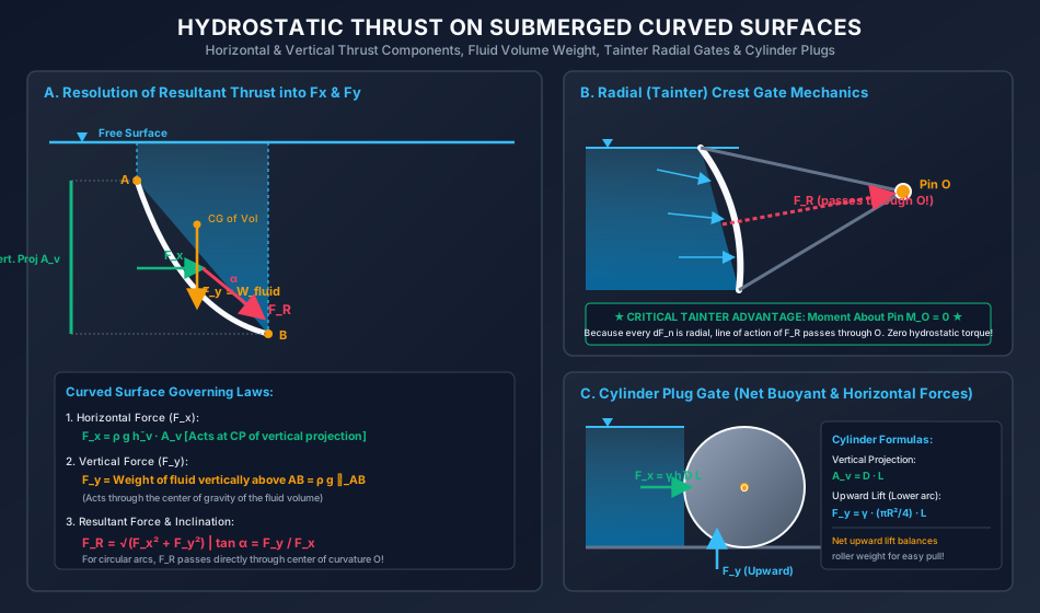
When a boundary surface is curved, the direction of normal pressure changes continuously from point to point. A direct scalar integration cannot yield the resultant force vector. Instead, the total force is determined by evaluating its orthogonal components:
                Free Surface
       +-------------------------------+
       |             |                 |
       |             | Fluid Volume ∀  |
       |             |                 |
   A_v |             +---...           |
       |                    \ Curved   |
       |                     \ Surface |
       |                      +        |
       +-------------------------------+
5.1 Horizontal Component ()
Consider an elemental curved area with an outward unit normal vector making an angle with the horizontal -axis. The horizontal projection of onto a vertical plane perpendicular to is:
The horizontal hydrostatic force on is:
Integrating over the whole curved surface:
By definition of the centroid of the vertically projected area :
Where:
- is the area of the projection of the curved surface onto a vertical plane.
- is the vertical depth to the centroid of this projected vertical area .
- Line of Action of : acts horizontally through the center of pressure of the projected vertical area :
5.2 Vertical Component ()
The vertical component of hydrostatic pressure force on an elemental area is:
Where is the horizontal projection of . Since :
Where is the volume of the vertical fluid prism extending from the elemental area up to the free liquid surface.
Integrating over the entire curved boundary:
- Direction of :
- If the fluid lies above the curved surface, acts vertically downward.
- If the fluid lies beneath the curved surface (such that fluid pressure pushes upward from below), acts vertically upward with a magnitude equal to the weight of the imaginary (virtual) fluid column that would extend from the surface up to the level of the free surface.
- Line of Action of : passes vertically through the center of gravity (centroid) of the fluid volume .
5.3 Resultant Force Magnitude & Direction
The magnitude of the resultant hydrostatic force is:
The inclination angle of the resultant force with the horizontal is:
5.4 The Radial (Tainter) Gate Principle
For cylindrical or spherical surfaces of radius :
- Every normal elemental force vector is directed perpendicular to the tangent, which coincides with the radial direction pointing toward the center of curvature .
- Because every constituent elemental force passes through the center of curvature , the resultant force vector must also pass directly through .
- When a radial gate is hinged at its center of curvature :
- Engineering Significance: The hydrostatic pressure produces zero moment (zero torque) about the trunnion pin. To lift or rotate the gate, the operating hoist only needs to overcome:
- The self-weight of the gate assembly.
- The frictional resistance at the side water seals and trunnion pin bearings.
6. Complete Mathematical Formulations & Derivations Summary
| Configuration | Force Components | Center of Pressure / Point of Action | Governing Conditions |
|---|---|---|---|
| Submerged Plane Surface (General) | Valid for any plane surface inclined at angle to horizontal. | ||
| Vertical Plane Surface | . | ||
| Horizontal Plane Surface | ; pressure is uniform; coincides with centroid . | ||
| Curved Surface (Horizontal Component) | Projected area onto vertical plane (). | ||
| Curved Surface (Vertical Component) | Centroid of vertical fluid volume | Weight of real or virtual fluid column extending to free surface. | |
| Curved Surface (Resultant Force) | For circular arcs, passes through center of curvature . |
7. Visual Architectural Diagrams
Diagram 1: Submerged Plane Surfaces & Center of Pressure Derivation
The following diagram illustrates the geometry of an inclined submerged plane surface, the derivation of , standard geometric shapes with their center of pressure depths, and sluice gate moment equilibrium:
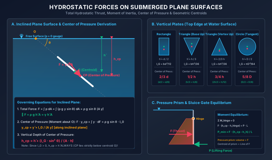
Diagram 2: Hydrostatic Thrust on Submerged Curved Surfaces & Radial Gates
The following diagram demonstrates the orthogonal decomposition of hydrostatic force on curved boundaries ( and ), fluid volume centroids, Tainter gate zero-torque mechanics, and cylinder roller plug gate forces:
8. Worked Numerical Problems
Problem 1: Inclined Sluice Gate Equilibrium & Minimum Hoist Force (GATE / ESE Standard)
Statement: A rectangular sluice gate of length (along the incline) and width is installed across an outlet channel inclined at an angle of to the horizontal. The gate is hinged along its top horizontal edge, which is situated at a vertical depth of below the water surface. The downstream side of the gate is open to atmospheric air. Take density of water and .
- Compute the total hydrostatic thrust acting on the gate.
- Determine the distance of the center of pressure from the hinge along the gate plate () and its vertical depth .
- Calculate the minimum normal force applied at the bottom edge required to open the gate (neglecting gate self-weight and hinge friction).
Solution:
Geometry and Coordinate Setup:
- Let be the intersection of the inclined gate plane with the free water surface.
- Distance along the incline from to the top hinged edge:
- Distance along incline to centroid of the gate:
- Vertical depth of centroid : (Check: )
- Gate surface area:
Part 1: Total Hydrostatic Force:
Part 2: Center of Pressure:
- Centroidal second moment of area about axis parallel to hinge:
- Distance of center of pressure along inclined plane from :
- Offset from centroid along plate:
- Lever arm distance from top hinge to center of pressure: (Check: )
- Vertical depth of center of pressure:
Part 3: Minimum Lifting Force : Taking moments about the top hinge pin (): The hydrostatic thrust creates a closing moment:
The normal lifting force applied at the bottom edge acts at full length :
Problem 2: Center of Pressure Comparison for Vertical Triangular Plates (ESE / SSC JE Standard)
Statement: A vertical triangular opening in the vertical face of a reservoir dam has a base and height . Water stands level with the top edge of the plate ().
- Case A: The base is horizontal at the water surface, and the vertex points vertically downward.
- Case B: The vertex is at the water surface, and the base is horizontal at the bottom. For both cases, calculate:
- The total hydrostatic force .
- The vertical depth of the center of pressure .
Solution:
Common Geometric Properties:
- Area of triangle:
- Centroidal moment of inertia:
Case A: Base at Water Surface, Vertex Pointing Down
- The centroid of a triangle lies at one-third height from the base:
- Total Hydrostatic Force :
- Center of Pressure : Notice that:
Case B: Vertex at Water Surface, Base Pointing Down
- The centroid lies at two-thirds height from the vertex:
- Total Hydrostatic Force : Notice that because the centroid is twice as deep!
- Center of Pressure : Notice that:
Summary Comparison:
| Parameter | Case A (Base Up) | Case B (Vertex Up) | Ratio (B / A) |
|---|---|---|---|
| Centroid Depth | () | () | |
| Total Thrust | |||
| Center of Pressure | () | () | |
| Offset | () | () |
Problem 3: Resultant Hydrostatic Thrust on a Radial Tainter Gate (GATE Standard)
Statement: A radial spillway crest gate has a cylindrical skin plate of radius and width . The gate retains water to a depth of above the spillway sill. The trunnion pin hinge is situated at the center of curvature of the cylindrical arc at the exact elevation of the upstream water surface. Take and .
- Compute the horizontal component of hydrostatic force and its line of action.
- Compute the vertical component of hydrostatic force .
- Determine the magnitude and direction of the resultant hydrostatic force .
- Determine the hydrostatic moment about the trunnion pin .
Solution:
Geometry of the Radial Gate:
- Upstream water surface elevation: .
- Sill elevation: .
- Trunnion pin is at .
- Gate skin plate radius .
- Angle subtended by the sill with the horizontal:
- Horizontal distance from pin to sill:
Part 1: Horizontal Component :
- The vertical projection of the submerged cylindrical arc is a rectangle of height and width :
- Depth to centroid of the vertical projection:
- Horizontal force:
- Line of action of (Center of pressure of rectangle touching water surface): Elevation above sill .
Part 2: Vertical Component : The vertical force equals the weight of the fluid volume vertically enclosed between the curved gate face and the water surface.
- In cross-section, this area is the area between the horizontal water surface, the vertical line through the sill, and the circular arc:
- Area of sector:
- Area of triangle:
- Enclosed cross-sectional area:
- Total volume of water above the gate:
- Vertical force: (Acting vertically downward because water is situated directly above the gate skin plate).
Part 3: Resultant Hydrostatic Force :
Direction with horizontal:
Part 4: Moment About Trunnion Pin : Because the gate profile is a circular cylinder of radius , every elemental hydrostatic pressure vector acts normal to the surface, pointing radially toward the center of curvature . The resultant force passes directly through pin .
9. Common Traps, Fallacies & Edge Cases
Trap 1: Confusing Inclined Distance with Vertical Depth
- The Fallacy: Using the distance along the inclined plate instead of vertical depth when computing total force ().
- The Physical Reality: Hydrostatic pressure depends strictly on the vertical column height of liquid (). The total force is always .
Trap 2: Locating the Center of Pressure Above or At the Centroid
- The Fallacy: Assuming that symmetric plates submerged vertically have their center of pressure at the geometric center.
- The Physical Reality: Because pressure increases linearly with depth, the lower half of the plate experiences higher pressure intensity than the upper half. Consequently, the centroid of the pressure prism is always shifted downward. For any non-horizontal plate, strictly.
Trap 3: Neglecting Virtual Fluid Volume on Underside of Curved Gates
- The Fallacy: If water is beneath a curved boundary, setting because there is no liquid "above" it.
- The Physical Reality: Water beneath a curved surface pushes vertically upward. By hydrostatic statics, this upward force equals the weight of the imaginary column of liquid that would extend from the curved surface vertically upward to the level of the free water surface.
Trap 4: Assuming Tainter Gates Require Huge Lifting Power
- The Fallacy: Believing that because on a Tainter gate, a hoist must exert over to open it.
- The Physical Reality: The resultant force passes directly through the trunnion pin, producing zero torque. The hoist only needs to overcome pin bearing friction () and the self-weight of the gate.
Trap 5: Pressure Prism on Non-Rectangular Plates
- The Fallacy: Applying the centroid of a trapezoidal pressure prism ( depth) to triangular or circular plates.
- The Physical Reality: The pressure prism concept works directly only when the plate width is constant. For triangles or circles, width varies with depth, requiring integration or the parallel axis theorem ().
10. Multi-Exam Multi-Choice & Conventional Practice Set
Q1. GATE CE (1 Mark) — Center of Pressure Depth Ratio
Question: A vertical rectangular gate of depth is submerged in water such that its top edge coincides with the free water surface. The ratio of the depth of the center of pressure to the depth of the centroid is:
- (A)
- (B)
- (C)
- (D)
Solution: For a rectangular plate of depth with top edge at surface:
- Centroid depth:
- Center of pressure depth:
- Ratio:
Correct Answer: (B)
Q2. UPSC ESE (Paper-II) — Hydrostatic Force on Inclined vs Vertical Surface
Question: A circular disc of diameter is submerged in water. In Position 1, it is oriented vertically with its center at depth . In Position 2, it is tilted at an angle of to the horizontal while keeping its center at the same depth . Which of the following statements is correct regarding the total hydrostatic force and the center of pressure ?
- (A) Both and remain unchanged.
- (B) remains unchanged, but in Position 2 is closer to the centroid than in Position 1.
- (C) decreases in Position 2, but remains unchanged.
- (D) remains unchanged, but in Position 2 is deeper than in Position 1.
Solution:
- Total force: . Since and area are identical in both positions, remains unchanged.
- Center of pressure offset:
- For vertical position (): .
- For tilted position (): . Therefore, is halved in Position 2, meaning moves closer to the centroid. Correct Answer: (B)
Q3. SSC JE — Vertical Triangle Center of Pressure
Question: A triangular plate of height is submerged vertically in water with its vertex at the free water surface and its base horizontal. The depth of the center of pressure below the water surface is:
- (A)
- (B)
- (C)
- (D)
Solution: With vertex at the water surface:
Correct Answer: (C)
Q4. State AE — Horizontal Component of Curved Surface
Question: The horizontal component of the hydrostatic force on any submerged curved surface is equal to:
- (A) The weight of the liquid column vertically above the surface.
- (B) The force on the projection of the curved surface onto a horizontal plane.
- (C) The force on the projection of the curved surface onto a vertical plane.
- (D) The product of the pressure at the lowest point and the surface area.
Solution: By integrating , the horizontal force component is equal to the hydrostatic force exerted on the vertical projection of the curved surface: . Correct Answer: (C)
Q5. RRB JE — Radial Gate Trunnion Moment
Question: Why are radial gates (Tainter gates) preferred over vertical lift slide gates for large dam spillway crests?
- (A) They require no side seals.
- (B) The resultant water pressure passes through the trunnion pin, resulting in zero hydrostatic moment.
- (C) They can withstand much higher water temperatures.
- (D) The total water thrust on a curved gate is always zero.
Solution: Because all elemental water pressures act normal to the circular skin plate, every force line passes through the center of curvature (the trunnion hinge pin). The hydrostatic moment about the hinge is zero, dramatically reducing the hoist capacity required to raise the gate. Correct Answer: (B)
11. Cross-Subject Synthesis & Practical Field Applications
1. Water Resources & Dam Engineering: Stability of Gravity Dams
In the structural design of concrete gravity dams, the upstream water thrust produces an overturning moment about the toe (). To resist overturning and sliding:
- Factor of Safety Against Overturning:
- Factor of Safety Against Sliding: Accurate center of pressure determination at is essential for computing the eccentricity to eliminate tensile stresses at the dam heel (Middle-Third Rule).
2. Environmental & Wastewater Treatment: Automatic Flap Gates
Automatic tidal flap gates protect storm drainage outlets from backflow during high tides. Designed as inclined plane gates hinged at the top, they open automatically when internal drainage water head creates an opening moment exceeding the external sea water thrust moment.
3. Geotechnical Engineering: Braced Excavation Sheet Piles
In deep foundation trenches, hydrostatic groundwater pressure behind sheet pile walls acts concurrently with active Rankine earth pressure. Because water pressure increases linearly () with center of pressure at , walers and struts must be spaced to support this concentrated lower thrust.
12. Comprehensive Summary & Formula Cheatsheet
Quick Revision Cards
================================================================================
             HYDROSTATIC FORCES ON PLANE & CURVED SURFACES CHEATSHEET
================================================================================

1. SUBMERGED PLANE SURFACES:
   - Magnitude: F = ρ g h̄ A = γ h̄ A  (Independent of angle θ!)
   - Distance along plane: y_cp = ȳ + I_G / (A ȳ)
   - Vertical depth:       h_cp = h̄ + (I_G sin² θ) / (A h̄)
   - Since I_G > 0:        h_cp > h̄ ALWAYS (CP lies strictly below centroid)
   - At deep immersion:    As h̄ -> ∞, h_cp -> h̄ (Uniform pressure limit)
   - Horizontal plate:     θ = 0° -> h_cp = h̄

2. STANDARD VERTICAL SHAPES (Top edge touching water surface):
   - Rectangle (b x d):             h̄ = d/2,   h_cp = 2/3 d
   - Triangle (Base at surface):     h̄ = h/3,   h_cp = 1/2 h
   - Triangle (Vertex at surface):   h̄ = 2/3 h, h_cp = 3/4 h
   - Circle (Tangent to surface):    h̄ = D/2,   h_cp = 5/8 D
   - Semicircle (Flat edge up):      h̄ = 4R/(3π), h_cp = (3π/16) R ≈ 0.589 R

3. SUBMERGED CURVED SURFACES:
   - Horizontal Component: F_x = ρ g h̄_v A_v
     (Thrust on vertical projection A_v; acts at CP of A_v)
   - Vertical Component:   F_y = ρ g ∀
     (Weight of fluid vertically above surface up to free surface)
   - Virtual Fluid Rule:   If fluid is below, F_y acts UPWARD with magnitude
                           equal to imaginary fluid weight above it.
   - Resultant Force:      F_R = √(F_x² + F_y²),  tan α = F_y / F_x

4. RADIAL (TAINTER) GATES:
   - All normal pressure vectors are radial -> pass through center of curvature O
   - Resultant F_R passes through trunnion pin O
   - Hydrostatic moment about pin: M_O = 0 (Zero torque advantage!)
================================================================================
References & Standard Codes
- Streeter, V. L., Wylie, E. B., and Bedford, K. W., Fluid Mechanics, 9th Edition, McGraw-Hill, New York.
- White, F. M., Fluid Mechanics, 8th Edition, McGraw-Hill Education, 2016.
- Modi, P. N., and Seth, S. M., Hydraulics and Fluid Mechanics Including Hydraulics Machines, Standard Book House, New Delhi.
- IS 6934:1998, Recommendations for Hydraulic Design of High Head Sluices and Crest Gates, Bureau of Indian Standards.
- IS 4410 (Part 15/Sec 1):1973, Glossary of Terms Relating to River Valley Projects: Gates and Valves, BIS.