Hydrodynamic Jet Propulsion & Impact of Free Jets: Force on Flat, Inclined & Curved Fixed and Moving Vanes
In this chapter (5 topics)
On this page
- 1. Module Overview & Pedagogical Scope
- 2. Official Examination Syllabus Mapping
- 3. Fundamental Physical Principles & Governing Assumptions
- 4. Mathematical Derivations & Rigorous Proofs
- Sub-derivation A: Fixed Vertical and Inclined Flat Plates
- Sub-derivation B: Moving Flat Plates — Single Vane vs Series of Vanes
- Sub-derivation C: Curved Moving Vanes & General Velocity Triangles
- Sub-derivation D: Hydrodynamic Jet Propulsion of Ships
- 5. Technical Diagrams & Interactive Architectural Schematics
- Figure 1: Impact of Free Jets on Fixed and Moving Plates
- Figure 2: Curved Vane Velocity Triangles & Ship Jet Propulsion
- 6. Comparative Engineering Analysis & Parameter Regimes
- 7. Worked Numerical Examples (Pre-Calculated & Verified)
- Problem 1: Water Jet Impinging on a Fixed Inclined Plate
- Problem 2: Single Curved Moving Vane vs Wheel-Mounted Series of Vanes
- Problem 3: Hydrodynamic Jet Propulsion of a Fast Patrol Boat
- 8. High-Yield Examination Traps & Ambiguities
- 9. Real-World Engineering Applications & Case Studies
- 10. Cross-Disciplinary & Downstream Dependencies
- 11. Summary Formula Cheat Sheet & Memory Anchors
- 12. Comprehensive References & Standard Codes
1. Module Overview & Pedagogical Scope
The hydrodynamic impact of free fluid jets on solid boundaries represents the foundational physical bridge connecting basic fluid dynamics (conservation of linear momentum) to advanced rotodynamic machinery, including Pelton impulse turbines, Francis reaction runners, and water-jet propulsion systems. When a high-velocity fluid stream discharging from a converging nozzle impinges upon a solid vane, the boundary forces the fluid to change its magnitude and direction of velocity. By Newton's second and third laws, the rate of change of momentum of the fluid stream exerts an equal and opposite dynamic thrust upon the vane.
                  Impulse-Momentum Hydrodynamic Transfer
    ┌────────────────┐         High-Speed Jet        ┌──────────────────┐
    │ Nozzle Exit    ├──────────────────────────────►│ Deflector Vane  │
    │ Total Head H   │   Velocity V = Cv√(2gH)       │ Fixed or Moving  │
    └────────────────┘                               └────────┬─────────┘
                                                              │ Deflection ΔV
                                                              ▼
                                                     Dynamic Force Fx = ṁ ΔVx
                                                     Work Done W = Fx · u
This master technical module develops the comprehensive theoretical formulation of jet-vane interaction across the complete spectrum of engineering configurations:
- Fixed Boundaries: Stationary flat plates oriented perpendicular or inclined to the jet, and stationary curved vanes with symmetrical or tangential inlet impact.
- Moving Boundaries: Single flat and curved vanes translating at velocity (where relative approach velocity governs mass interception), contrasted fundamentally with a continuous series of vanes mounted on the periphery of a revolving wheel (where the entire nozzle discharge is intercepted without mass deficit).
- Euler's Turbine Equation: Generalization to moving curved vanes via velocity triangles (whirl and flow components).
- Hydrodynamic Jet Propulsion: Reaction thrust generated by water jets in marine patrol vessels, contrasting lateral amidships intake versus forward-facing scoop intake configurations.
2. Official Examination Syllabus Mapping
Website note: this mapping is from the author’s notes. It has not been checked against the official notification for each examination; confirm the current syllabus with the examining body.
| Examination Body | Syllabus Code & Topics | Core Weightage & Target Focus |
|---|---|---|
| GATE (Civil Engineering) | Water Resources: Fluid Mechanics & Hydraulic Machinery — Impulse-momentum principle applied to fluid jets; Impact of jets on stationary and moving flat and curved vanes; Work done and efficiency; Introduction to impulse turbines. | High (1 to 2 questions yearly): Contrast between single moving plate vs series of vanes on wheel; maximum efficiency conditions; velocity triangles. |
| UPSC ESE (Prelims & Mains) | Paper-II: Fluid Mechanics and Hydraulic Machines — Dynamic action of fluid jets, force exerted on flat plates (normal, inclined, hinged), force on curved vanes, work done and hydraulic efficiency, jet propulsion of ships. | Very High (Core Subject): Formal mathematical proofs for discharge division , vs , and multi-part numerical problems. |
| SSC JE & RRB JE | Civil / Mechanical Engineering — Impact of jets, force on vertical and inclined plates, maximum efficiency of jet striking moving curved vane. | Direct / Objective: Direct formula evaluation for , , and optimal velocity ratios . |
| State AE / JE (All States) | Fluid Mechanics & Machinery — Jet impact force derivations, work done per second, blade velocity triangles, ship jet propulsion efficiency. | Objective & Numerical: Plate reaction forces, efficiency peaks, and discharge ratio calculations. |
3. Fundamental Physical Principles & Governing Assumptions
- Newtonian Incompressible Flow: The fluid is water or an equivalent liquid of uniform constant density and dynamic viscosity .
- Impulse-Momentum Principle: The net hydrodynamic force exerted by the fluid on a solid vane is equal to the time rate of decrease of fluid linear momentum in that direction:
- Neglect of Elevation Head: The vertical dimensions of the vane are negligible compared to the kinetic head of the jet ().
- Atmospheric Pressure Surrounding Free Jet: The free jet discharges into the atmosphere, so static pressure is uniformly atmospheric everywhere (). By Bernoulli's equation for ideal frictionless flow, the magnitude of relative velocity remains constant along the vane: If surface friction is considered, the exit relative velocity is attenuated by a friction coefficient :
- Smooth Deflection: Fluid enters and leaves the vane tangentially without shock, splash, or separation at design flow rates.
- Mass Interception Distinction:
- Single Moving Vane: The plate flees the jet at velocity , so the mass of fluid striking the plate per second is reduced to .
- Series of Vanes on a Wheel Rim: As one vane moves away, the next vane enters the jet trajectory. Consequently, all fluid issued from the nozzle per second is intercepted by the wheel, giving .
4. Mathematical Derivations & Rigorous Proofs
========================================================================================
IMPACT OF JETS DERIVATION TAXONOMY
========================================================================================
Impulse-Momentum Principle: F = ṁ · (V_in - V_out)
       │
       ├─────────────────────────────────────────┐
       ▼                                         ▼
STATIONARY / FIXED VANES                  MOVING VANES
       │                                         │
       ├─► Flat Plate Normal: Fx = ρaV²          ├─► Single Moving Plate:
       │                                         │   ṁ = ρa(V-u), Fx = ρa(V-u)²
       ├─► Flat Plate Inclined (θ):              │   W = ρa(V-u)² u, η_max = 8/27 (29.63%)
       │   Fn = ρaV² sin θ                       │
       │   Q1/Q2 = (1+cos θ)/(1-cos θ)           ├─► Series of Moving Vanes on Wheel:
       │                                         │   ṁ = ρaV (Entire Jet Intercepted)
       └─► Curved Fixed Vane:                    │   Fx = ρaV(V-u), W = ρaV(V-u)u
           Fx = ρaV²(1 + cos θ)                  │   η_max = 50.0% (Flat), ~100% (Hemispherical)
                                                 │
                                                 ├─► General Velocity Triangles:
                                                 │   W = ṁ(Vw1·u1 ± Vw2·u2) (Euler Eq.)
                                                 │
                                                 └─► Ship Jet Propulsion:
                                                     Amidships: η = 2u(V-u)/V² (max 50%)
                                                     Forward:   η = 2u/(V+u)   (max 100%)
========================================================================================
Sub-derivation A: Fixed Vertical and Inclined Flat Plates
1. Fixed Vertical Flat Plate Normal to Jet:
Let a horizontal jet of cross-sectional area and velocity strike a smooth vertical plate normally. Upon impact, the jet splits symmetrically into two equal sheets discharging upwards and downwards parallel to the plate ().
Mass of fluid striking per second:
Applying the linear momentum equation in the -direction:
Since the fluid splits symmetrically, the transverse forces cancel:
Because the plate is stationary ():
2. Fixed Inclined Flat Plate:
Let the plate be inclined at an angle to the horizontal axis of the approaching jet. The normal to the plate makes an angle with the jet axis.
Because the plate is smooth, no shear force can act along the surface (). Consequently, the hydrodynamic force must act purely normal to the plate surface ().
Resolving approach velocity normal to the plate:
After impact, the fluid glides along the plate, so exit velocity normal to the plate is zero ().
The normal force exerted on the plate is:
Resolving into coordinate components:
3. Derivation of Discharge Splitting Ratio ():
Let be the incoming discharge (). Upon impact, it divides into discharge deflecting along the upward plate edge and along the downward plate edge. By continuity:
Because the plate is frictionless, the fluid experiences zero net force in the direction parallel to the plate ():
The component of incoming velocity parallel to the plate is . The exiting fluid streams travel with speed in opposite directions along the plate:
Dividing by :
We have a system of two linear equations:
Adding the two equations:
Subtracting the two equations:
Dividing by :
Limiting Cases:
- When (normal plate): (perfect 50:50 symmetrical split).
- When (plate parallel to jet): (no fluid deflected downwards).
Sub-derivation B: Moving Flat Plates — Single Vane vs Series of Vanes
1. Single Flat Plate Moving in Direction of Jet:
Consider a single flat vertical plate translating horizontally away from the nozzle at uniform speed ().
Mass Interception Deficit: Because the plate moves away at speed , the relative velocity at which fluid overtakes the plate is . Therefore, the mass of fluid reaching and striking the plate per second is:
Relative velocity at inlet: .
Relative velocity at outlet: (in -direction).
Hydrodynamic force exerted on the plate:
Work done per second (Power developed):
Kinetic energy supplied by the jet per second:
Hydraulic Efficiency ():
To find the condition for maximum efficiency, differentiate with respect to blade speed and equate to zero:
Discarding the trivial solution (which gives ):
Substituting into the efficiency formula:
2. Series of Flat Plates Mounted on a Wheel Rim:
In practical hydraulic turbines, a series of identical vanes are mounted uniformly around the periphery of a rotating wheel of radius . As each vane moves out of reach, another vane immediately enters the jet trajectory.
Zero Mass Deficit: The total mass of fluid discharged by the nozzle per second is fully intercepted by the revolving wheel:
The velocity change experienced by each parcel of fluid in the direction of motion is :
Work done per second:
Hydraulic Efficiency:
Differentiating with respect to :
Substituting :
Core Examination Contrast: Moving from a single moving flat plate to a wheel-mounted series of flat plates increases maximum theoretical efficiency from () to (), while the optimal blade-to-jet speed ratio shifts from to !
Sub-derivation C: Curved Moving Vanes & General Velocity Triangles
When a jet strikes a curved vane tangentially or at its center, the fluid is deflected smoothly through an angle , where is the vane angle at exit.
1. Symmetrical Curved Moving Vane (Central Impact):
Let a jet strike the central tip of a symmetrical curved vane moving with speed .
Relative velocity at inlet: .
If the vane is smooth (), relative speed is conserved: .
If rough with friction factor : .
The component of exit relative velocity in the backward direction is .
Absolute velocity component at exit in direction of motion:
Change in velocity in -direction:
Force and Work for Series of Curved Vanes on Wheel:
Maximum efficiency occurs at :
- For a frictionless vane () and a semicircular bucket (, deflection ):
- In practical Pelton buckets, is made (deflection ) to avoid the exiting jet striking the back of the subsequent bucket, yielding theoretical efficiencies of .
2. General Velocity Triangles (Euler Turbine Formulation):
Let:
- : Absolute velocity at inlet and outlet.
- : Linear tangential velocity of vane at inlet and outlet.
- : Relative velocity of fluid with respect to vane.
- : Guide vane / nozzle angle (angle between and ).
- : Vane inlet angle (angle between and ).
- : Vane outlet angle (angle between and ).
- : Absolute fluid discharge angle (angle between and ).
- : Whirl velocities ().
- : Flow velocities ().
The torque exerted on the runner is:
Work done per second:
(The sign is when and exit whirl opposes blade motion; when and exit whirl follows blade motion.)
Sub-derivation D: Hydrodynamic Jet Propulsion of Ships
In marine jet propulsion, water is ingested by a pump through intake orifices, pressurized, and discharged backwards through stern nozzles with relative velocity relative to the vessel. The vessel moves forward at constant cruising velocity .
Let:
- : Total cross-sectional area of discharge nozzles.
- : Exit velocity of jet relative to the ship ().
- : Total volume flow rate ().
- Absolute velocity of exit jet relative to earth: (backwards).
1. Forward Propulsive Thrust ():
By linear momentum, the forward reaction thrust is the mass flow multiplied by the net increase in velocity in the backward direction:
Useful propulsive power:
2. Case A: Inlet Orifices at Right Angles to Motion (Amidships Intake):
Water enters the ship perpendicular to the direction of travel, bringing zero initial momentum along the vessel's axis of motion.
To move with the ship, this ingested mass must first be accelerated to forward speed , and then pumped out at relative velocity . The total mechanical energy supplied to the fluid by the pump per second is:
Propulsive Efficiency ():
Differentiating with respect to :
3. Case B: Inlet Orifices Facing Ahead (Direction of Motion):
When intake scoops face forward, the water already possesses forward relative velocity as it enters the ship.
The pump only needs to augment the velocity head from to :
Propulsive Efficiency ():
As (with very large discharge to maintain thrust), . Forward-facing scoops are dramatically superior to amidships intake!
5. Technical Diagrams & Interactive Architectural Schematics
Figure 1: Impact of Free Jets on Fixed and Moving Plates
This schematic presents the force decomposition on stationary vertical and inclined plates, the quantitative discharge splitting ratio , and the fundamental efficiency contrast between a single translating plate vs a turbine wheel series of vanes.
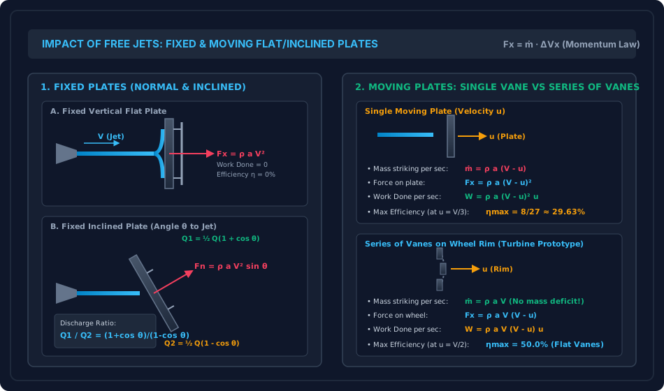
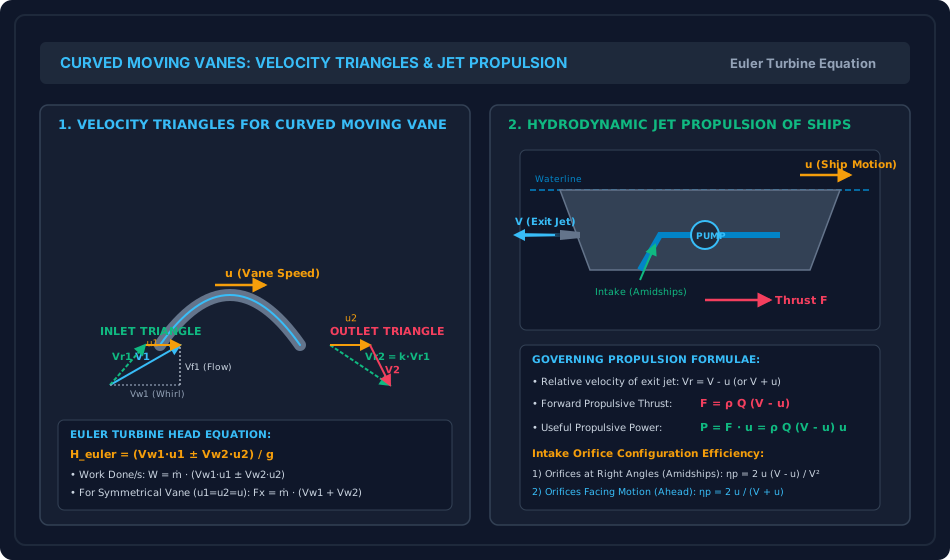
Figure 2: Curved Vane Velocity Triangles & Ship Jet Propulsion
This schematic details the full inlet and outlet velocity triangles for a curved moving turbine vane, Euler's head formulation, and the hydrodynamics of marine water-jet propulsion contrasting amidships vs forward intake configurations.
6. Comparative Engineering Analysis & Parameter Regimes
| Vane / Impingement Configuration | Mass Flow Striking Vane () | Normal Force () or Thrust () | Work Done per Second () | Optimal Speed Ratio () | Maximum Theoretical Efficiency () | Key Engineering Application |
|---|---|---|---|---|---|---|
| Fixed Vertical Flat Plate | Energy dissipation blocks, baffles | |||||
| Fixed Inclined Flat Plate () | Flow deflectors, spillway chutes | |||||
| Fixed Curved Vane (Central) | Reversing nozzles, Pelton testing | |||||
| Single Moving Flat Plate | () | Target deflection boards | ||||
| Series of Flat Plates on Wheel | () | Primitive water wheels | ||||
| Single Moving Semicircular Vane | () | Single bucket test rigs | ||||
| Series of Curved Vanes on Wheel | Up to () | Modern Pelton Wheel Turbines | ||||
| Jet Propulsion (Amidships Orifice) | Auxiliary marine thrusters | |||||
| Jet Propulsion (Forward Scoops) | Fast ferry / naval waterjets |
7. Worked Numerical Examples (Pre-Calculated & Verified)
Problem 1: Water Jet Impinging on a Fixed Inclined Plate
Problem Statement: A horizontal water jet of diameter () issues from a nozzle at a uniform velocity and strikes a smooth, stationary flat plate. The plate is inclined at an angle to the axis of the approaching jet. Taking water density as , determine:
- The cross-sectional area and volumetric discharge of the jet.
- The normal force exerted on the plate.
- The horizontal force component (in the direction of the jet) and vertical force component .
- The rate of discharge and deflecting into the two streams along the plate surface.
- The ratio .
Step-by-Step Solution:
1. Jet Geometry and Discharge:
Total mass flow rate:
2. Normal Force on Plate ():
3. Coordinate Components of Force ( and ):
4. Discharge Splitting ( and ):
Check: .
5. Discharge Ratio ():
Problem 2: Single Curved Moving Vane vs Wheel-Mounted Series of Vanes
Problem Statement: A nozzle of exit diameter () discharges water horizontally at . The jet impinges upon a curved vane moving in the same direction at velocity . The vane deflects the jet through an angle (so the vane exit tip angle is ). Due to surface friction across the vane, the exit relative velocity is attenuated to of the inlet relative velocity ().
Compare the performance under two distinct operating conditions:
- Case A: The jet strikes a single moving curved vane.
- Case B: The jet strikes a continuous series of curved vanes mounted around the periphery of a large wheel revolving at blade pitch line speed . Determine the power developed in kW, the hydraulic efficiency, the optimal wheel speed , and the maximum possible efficiency .
Step-by-Step Solution:
Common Geometric & Hydraulic Parameters:
Total kinetic energy supplied by the nozzle jet per second:
Relative velocity at inlet:
Relative velocity at outlet:
Vane exit factor:
Case A: Single Moving Curved Vane:
- Mass of fluid striking the vane per second:
- Hydrodynamic force in direction of motion:
- Work done per second (Power):
- Hydraulic efficiency:
Case B: Series of Curved Vanes on Wheel Rim:
- Mass of fluid striking the wheel per second (zero deficit):
- Dynamic thrust on the wheel:
- Power developed:
- Hydraulic efficiency:
- Optimal blade speed and maximum theoretical efficiency:
Problem 3: Hydrodynamic Jet Propulsion of a Fast Patrol Boat
Problem Statement: A fast naval patrol boat of displacement mass cruises at a steady velocity (). The vessel is propelled by two stern jet nozzles, each having an exit diameter (). Water discharges through the nozzles with a relative velocity directed backwards relative to the boat. Seawater density is .
Calculate:
- Total discharge and mass flow rate .
- The forward propulsive thrust and useful propulsive power delivered to the hull.
- The mechanical power required from the pump and the propulsive efficiency assuming water is ingested amidships through orifices perpendicular to the boat's motion.
- The mechanical power required and propulsive efficiency if the water is ingested through forward-facing intake scoops.
Step-by-Step Solution:
1. Nozzle Area and Total Discharge:
2. Forward Propulsive Thrust and Useful Power: Absolute backward exit velocity of jet into still water:
Forward propulsive thrust:
Useful propulsive power:
3. Marine Configuration 1: Amidships Orifices (Perpendicular Intake): Since water is scooped with zero initial axial velocity, the pump supplies energy to accelerate the mass from rest to relative speed :
Propulsive efficiency:
Formula Check:
4. Marine Configuration 2: Forward-Facing Intake Scoops: With forward scoops, water enters with ram recovery head, entering at velocity . The pump only imparts head :
Propulsive efficiency:
Formula Check:
8. High-Yield Examination Traps & Ambiguities
- Mass Striking Rate: Single Plate vs Series of Vanes:
- Trap: Using for a Pelton wheel or series of vanes mounted on a rotor.
- Anchor: A single moving plate flees the jet, intercepting only . A series of vanes on a wheel intercepts all fluid, so the mass rate is strictly . Misapplying the single-vane formula drops calculated turbine power by .
- Discharge Splitting on Inclined Plate:
- Trap: Thinking and .
- Anchor: The division is derived strictly from momentum balance parallel to the frictionless plate: and .
- Jet Propulsion Efficiency Formula Confusion:
- Trap: Using when the problem statement explicitly specifies orifices placed amidships or at right angles to motion.
- Rule:
- Amidships Orifices: (maximum theoretical efficiency is capped at ).
- Forward Scoops: (efficiency can approach as ).
- Vane Deflection Angle vs Vane Exit Angle:
- Trap: Confounding the deflection angle with the blade tip angle .
- Anchor: If a jet is deflected through , the exit vane angle is . In the force formula , the angle is the acute blade angle, not the deflection angle.
- Normal Force vs Horizontal Force on Inclined Plate:
- Trap: Equating to .
- Rule: The hydrodynamic pressure creates . The force in the original jet direction is .
9. Real-World Engineering Applications & Case Studies
- Hydroelectric Pelton Runners: Impulse turbines in high-head hydroelectric plants (such as Bhakra or Koyna) operate directly on the principles of series curved moving vanes. By employing double-hemispherical split buckets with a central splitter ridge, the jet is cleanly split into two streams deflected through , achieving hydraulic runner efficiencies exceeding .
- Naval Water-Jet Propulsion (HamiltonJet / KaMeWa): High-speed patrol catamarans and littoral combat ships replace conventional screw propellers with axial waterjet propulsors. Operating with forward-facing flush intake scoops, they avoid cavitation damage at speeds exceeding () and provide exceptional maneuverability via steerable deflector nozzles.
- Pelton Deflector Servomechanisms: During sudden electrical load rejection (generator trip), closing the heavy needle nozzle rapidly would cause catastrophic water hammer in long penstocks. Modern Pelton turbines employ high-speed mechanical deflector plates that instantly pivot into the jet path, deflecting the free jet away from the buckets without altering the penstock flow rate.
10. Cross-Disciplinary & Downstream Dependencies
                     ┌──────────────────────────────────────────┐
                     │ FM-04-01 to FM-04-04: Fluid Dynamics &   │
                     │ Linear Momentum Conservation Equations   │
                     └────────────────────┬─────────────────────┘
                                          │
                                          ▼
┌────────────────────────────────────────────────────────────────────────────────────────┐
│ FM-08-01: HYDRODYNAMIC JET IMPACT & PROPULSION (FIXED/MOVING VANES, VELOCITY TRIANGLES) │
└───────────┬─────────────────────────────┬───────────────────────────────┬──────────────┘
            │                             │                               │
            ▼                             ▼                               ▼
┌───────────────────────┐   ┌───────────────────────────┐   ┌────────────────────────────┐
│ FM-08-02: Pelton      │   │ FM-08-03: Francis &       │   │ FM-08-04: Centrifugal      │
│ Wheel Turbines        │   │ Kaplan Reaction Runners   │   │ Pumps: Backward Curved     │
│ (Impulse Runner Dyn.) │   │ (Inward/Axial Euler Head) │   │ Impellers & Manometric H   │
└───────────────────────┘   └───────────────────────────┘   └────────────────────────────┘
- Upstream: Directly builds on Newton's momentum equation and Bernoulli energy conservation (
FM-04-01toFM-04-04). - Downstream Turbines: Serves as the direct mathematical stepping stone to Pelton wheel impulse mechanics (
FM-08-02) and Francis/Kaplan reaction velocity triangles (FM-08-03). - Downstream Pumps: Establishes the Euler head equation () required for centrifugal pump impeller analysis (
FM-08-04).
11. Summary Formula Cheat Sheet & Memory Anchors
- Fixed Normal Plate:
- Fixed Inclined Plate:
- Discharge Ratio (Inclined Plate):
- Single Moving Flat Plate:
- Series of Flat Plates on Wheel:
- Series of Curved Vanes on Wheel:
- Euler's Turbine Head:
- Jet Propulsion (Amidships):
- Jet Propulsion (Forward Scoops):
12. Comprehensive References & Standard Codes
- Modi, P. N., & Seth, S. M. (2020). Hydraulics and Fluid Mechanics Including Hydraulics Machines (22nd ed.). Standard Book House, New Delhi.
- Rajput, R. K. (2018). A Textbook of Fluid Mechanics and Hydraulic Machines (6th ed.). S. Chand & Company Ltd., New Delhi.
- Bansal, R. K. (2019). A Textbook of Fluid Mechanics and Hydraulic Machines (10th ed.). Laxmi Publications, New Delhi.
- White, F. M. (2016). Fluid Mechanics (8th ed.). McGraw-Hill Education, New York.
- Dixon, S. L., & Hall, C. A. (2014). Fluid Mechanics and Thermodynamics of Turbomachinery (7th ed.). Butterworth-Heinemann.
- IS 12800 (Part 1): 1993 — Guidelines for Selection of Hydraulic Turbines for Use in Hydroelectric Power Stations: Part 1 Selection of Turbine Type. Bureau of Indian Standards, New Delhi.