Fluid Masses Under Uniform Acceleration & Forced Vortex Rotation
In this chapter (4 topics)
On this page
- 1. Topic Metadata & Syllabus Mapping
- 2. Executive Summary & Core Engineering Concepts
- 3. Relative Equilibrium Fundamentals & General Formulation
- 4. Liquid Mass in Uniform Linear Acceleration
- 4.1 Horizontal Acceleration (ax) in Open Rectangular Tanks
- 4.2 Spilling Regimes & Critical Accelerations
- 4.3 Hydrostatic Forces & Newton's Second Law Verification
- 4.4 Combined Horizontal and Vertical Acceleration (Elevator Tanks)
- 5. Liquid Mass in Rigid-Body Uniform Rotation: The Forced Vortex
- 5.1 The Forced Vortex Field Equations
- 5.2 Derivation of the Free Surface Paraboloid of Revolution
- 5.3 Volume of a Paraboloid & Principle of Equal Rise and Fall
- 5.4 Critical Rotation Speeds in Open Tanks
- 5.5 Radial Pressure Distribution & Closed Cylinder Thrust
- 6. Complete Mathematical Formulations & Derivations Summary
- 7. Visual Architectural Diagrams
- Diagram 1: Linear Acceleration & Spilling Regimes
- Diagram 2: Forced Vortex Rotation & Paraboloid Profiles
- 8. Worked Numerical Problems
- Problem 1: Open Rectangular Tank Linear Acceleration & Spilling (GATE / ESE Standard)
- Problem 2: Open Cylindrical Tank Forced Vortex & Spilling (ESE / SSC JE Standard)
- Problem 3: Closed Rotating Cylindrical Vessel & Cover Plate Thrust (GATE Standard)
- 9. Common Traps, Fallacies & Edge Cases
- Trap 1: Confusing Paraboloid Volume with Cylinder Volume
- Trap 2: Neglecting the Formation of a Dry Floor Patch
- Trap 3: Confusing Forced Vortex with Free Vortex
- Trap 4: Assuming Net Horizontal Force on an Accelerated Tank is Zero
- 10. Multi-Exam Multi-Choice & Conventional Practice Set
- Q1. GATE CE (1 Mark) — Free Surface Shape in Forced Vortex
- Q2. UPSC ESE (Paper-II) — Free Surface Tilt in Accelerating Tank
- Q3. SSC JE — Rim Rise vs Center Fall in Rotating Cylinder
- Q4. State AE — Liquid in Free Fall
- Q5. RRB JE — Centrifugal Pressure Rise
- 11. Cross-Subject Synthesis & Practical Field Applications
- 1. Transportation Engineering: Road Tanker Sloshing & Baffle Design
- 2. Environmental & Water Engineering: Centrifugal Grit Separators & Hydrocyclones
- 3. Structural Concrete Manufacturing: Centrifugal Spinning of RCC Pipes
- 12. Comprehensive Summary & Formula Cheatsheet
- Quick Revision Cards
- References & Standard Codes
1. Topic Metadata & Syllabus Mapping
| Field | Description / Value |
|---|---|
| Topic ID | FM-02-04 |
| Module Title | Fluid Masses Under Uniform Acceleration & Forced Vortex Rotation (Relative Equilibrium) |
| Primary Subject | Fluid Mechanics & Hydraulic Machinery |
| Parent Chapter | Chapter 02: Fluid Statics & Manometry |
| GATE CE Mapping | Fluid Statics: Fluids in rigid-body motion, uniform linear acceleration, forced vortex flow, liquid surface profiles, pressure distribution. |
| UPSC ESE Mapping | Paper-II Fluid Mechanics: Relative equilibrium of liquids, containers under horizontal and vertical acceleration, liquid spilling criteria, cylindrical containers in uniform rotation, forced vortex mechanics, closed container pressures. |
| SSC JE / RRB JE | Slope of free water surface in accelerated tanks (), maximum acceleration without spilling, rotational speed and parabolic water profile in rotating cylinders. |
| Core Competencies | 1. Formulate the general Euler equation of motion for fluids in rigid-body relative equilibrium (). 2. Derive the free surface tilt equation and calculate liquid depths and spilling volumes. 3. Verify Newton's second law by integrating wall pressure prisms: . 4. Prove that the free surface in a forced vortex is a paraboloid of revolution () having a volume equal to half the circumscribing cylinder. 5. Compute radial pressure distributions, critical rotational speeds for dry floor exposure, and upward cover plate thrust in closed rotating tanks. |
2. Executive Summary & Core Engineering Concepts
In classical fluid statics, the fluid is at absolute rest relative to an inertial reference frame. However, when a fluid container undergoes uniform linear acceleration or constant rotational velocity, every fluid element eventually attains the same velocity as the container. In this steady state:
- There is no relative motion between adjacent fluid layers ().
- By Newton's Law of Viscosity (), shear stresses are identically zero throughout the fluid ().
This state is termed Relative Equilibrium (or Rigid-Body Fluid Motion). Because shear stresses vanish, the fundamental laws of fluid statics remain fully applicable, provided that the physical gravity vector is replaced by an effective gravity vector () incorporating D'Alembert's fictitious inertial body forces:
Two primary physical scenarios govern engineering practice:
- Uniform Linear Acceleration ():
- The surfaces of constant pressure (isobars) and the free liquid surface tilt into parallel inclined planes.
- The angle of inclination with the horizontal is given by .
- The net horizontal hydrostatic force difference between the rear and front walls exactly balances the inertial force: .
- Uniform Rigid-Body Rotation (The Forced Vortex, ):
- The fluid particles experience a centripetal acceleration () directed radially inward.
- The surfaces of constant pressure and the free liquid surface form paraboloids of revolution governed by .
- Because the volume of a paraboloid of revolution is exactly half the volume of the circumscribing cylinder, for an unspilled tank, the liquid rises at the rim by the exact same amount that it falls at the center:
3. Relative Equilibrium Fundamentals & General Formulation
Consider a fluid element of mass subjected to an arbitrary linear acceleration vector in a gravitational field .
Applying Newton's Second Law ():
Dividing throughout by :
Expanding in Cartesian coordinates:
The total differential of pressure is:
Core Theorem of Relative Equilibrium: Surfaces of constant pressure (isobars), including the free liquid surface where , satisfy :
4. Liquid Mass in Uniform Linear Acceleration
4.1 Horizontal Acceleration () in Open Rectangular Tanks
Consider an open rectangular tank of length , width , and height , filled with liquid to an initial still depth (freeboard ). Let the tank be accelerated horizontally along its length with uniform acceleration ().
       <----------------------- Length L ----------------------->
      +----------------------------------------------------------+
      |                                      Tilted Free Surface |
      |  h_rear                                          \       |
      |   |                                                \     |
      |   |         Still Water Level (h0)                   \   | h_front
      |   | - - - - - - - - - - - - - - - - - - - - - - - - - \  |
      |   v                                                     v|
      +==========================================================+
      <------ Rear Wall (Higher Depth)        Front Wall ------->
                     Acceleration a_x -------->
From the isobar equation ():
The free surface tilts by an angle relative to the horizontal:
- Point of Rotation: If no liquid spills out, by conservation of liquid volume, the free surface pivots about its geometric center ().
- Depth at Rear Wall ():
- Depth at Front Wall ():
4.2 Spilling Regimes & Critical Accelerations
-
Maximum Acceleration Without Spilling (): Water begins spilling over the rear rim when the liquid rise at the rear wall equals the initial freeboard :
-
Spilling Regime A: Bottom Floor Completely Covered (): If , liquid spills over the rear edge, pinning the rear depth at the tank rim:
As long as the front depth remains positive (), the residual liquid forms a trapezoid:
-
Spilling Regime B: Bottom Floor Partially Exposed (): When , the free surface intersects the bottom floor at a distance from the rear wall:
The remaining liquid forms a triangle:
4.3 Hydrostatic Forces & Newton's Second Law Verification
Because pressure varies linearly with depth along vertical walls:
- Hydrostatic thrust on the rear wall:
- Hydrostatic thrust on the front wall:
- Net horizontal force exerted by the walls on the fluid:
For an unspilled tank where and :
4.4 Combined Horizontal and Vertical Acceleration (Elevator Tanks)
When a container experiences simultaneous horizontal acceleration and vertical acceleration :
The free surface slope is:
Where:
- : Upward vertical acceleration (lift accelerating upward or decelerating downward). Apparent gravity increases ().
- : Downward vertical acceleration (lift accelerating downward). Apparent gravity decreases ().
- Free Fall State (): In free fall, the fluid becomes completely weightless. Hydrostatic pressure gradients vanish entirely (). Liquid assumes a spherical shape under surface tension alone.
5. Liquid Mass in Rigid-Body Uniform Rotation: The Forced Vortex
5.1 The Forced Vortex Field Equations
Consider an open cylindrical container of radius containing liquid of density rotated about its vertical central axis at constant angular velocity (, where ).
                     Rotation Axis
                           | ω
                           v
      +--------------------+--------------------+
      | \                                      /| Rim
      |   \                                  /  |
      |     \                              /    |
      | - - - - - - Still Level h0 - - - - - -  |
      |         \                      /        |
      |           \      Vertex      /          |
      |             +-----(z0)-----+            |
      +=========================================+
      <---------------- 2R --------------------->
In steady rotation, every fluid particle moves in a horizontal circle of radius at tangential velocity .
- The flow possesses uniform non-zero vorticity: (rotational flow).
- The particle experiences centripetal acceleration directed toward the rotation axis:
Applying the equations of motion in cylindrical coordinates ():
The total pressure differential is:
5.2 Derivation of the Free Surface Paraboloid of Revolution
Along any surface of constant pressure (including the free liquid surface where , ):
Integrating from the vertex of the paraboloid on the rotation axis ():
Fundamental Result: The free surface of a liquid in a forced vortex is a Paraboloid of Revolution whose vertical profile is a parabola concave upward.
At the outer wall ():
Where is the total vertical height of the paraboloid.
5.3 Volume of a Paraboloid & Principle of Equal Rise and Fall
The volume of an air paraboloid formed above the vertex is obtained by integrating circular elemental discs of radius and thickness :
Since :
Since :
Crucial Geometrical Rule: The volume of a paraboloid of revolution is exactly half the volume of its circumscribing cylinder.
By conservation of liquid volume in an unspilled cylindrical tank:
Therefore:
- Rise of liquid at the outer rim above still level:
- Depression of liquid at the center below still level:
- Liquid depth at outer rim:
- Liquid depth at center:
5.4 Critical Rotation Speeds in Open Tanks
-
Maximum Speed Without Spilling (): Spilling commences when the liquid rise at the rim reaches the initial freeboard :
-
Speed to Just Touch the Tank Floor at the Center (): If the container rim is at height and the vertex touches the floor (), the total height of the paraboloid is :
The remaining water volume is:
(Exactly half the cylinder capacity remains!).
-
High Speed Exposure: Formation of Dry Circle on Floor (): When rotated faster than , the vertex falls below the base floor (). A circular dry area of radius forms on the tank floor: At (floor), :
At (rim), :
Subtracting equations:
5.5 Radial Pressure Distribution & Closed Cylinder Thrust
Integrating between two arbitrary points and :
For a Closed Cylindrical Vessel Completely Filled with Liquid:
Let be the static gauge pressure at the top center ():
- Pressure Distribution on the Flat Top Cover Plate ():
- Total Upward Hydrostatic Thrust on Top Cover Plate (): Integrating over concentric annular rings:
- Maximum Pressure in Closed Rotating Vessel: Occurs at the bottom outer rim ():
6. Complete Mathematical Formulations & Derivations Summary
| Configuration | Governing Equation | Key Physical Variables |
|---|---|---|
| Linear Accel. Isobar Slope | : Horizontal accel., : Vertical accel. | |
| Max Linear Accel. (No Spill) | : Freeboard, : Tank length | |
| Net Wall Thrust (Linear) | ||
| Forced Vortex Free Surface | : Angular velocity (), : Radius | |
| Total Paraboloid Height | : Cylinder radius | |
| Rise and Fall (Unspilled) | Volume of paraboloid | |
| Max Rotation (No Spill) | ||
| Dry Floor Circle Radius | Formed when | |
| Closed Tank Top Lid Force | : Pressure at top center () | |
| Max Pressure (Closed Tank) | Located at bottom outer rim |
7. Visual Architectural Diagrams
Diagram 1: Linear Acceleration & Spilling Regimes
The following diagram illustrates free surface tilt under horizontal acceleration, the effective gravity vector, combined 2D elevator acceleration, and the three spilling regimes:
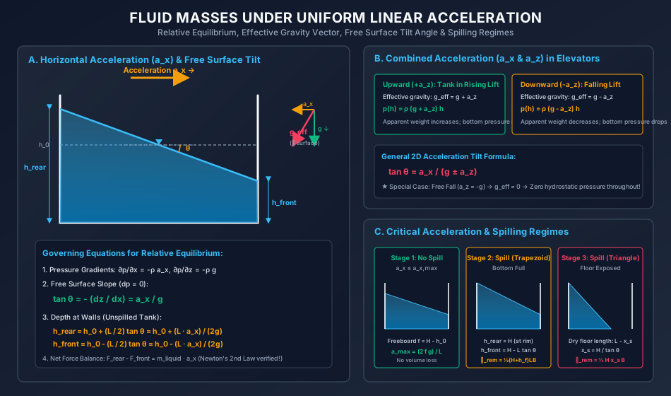
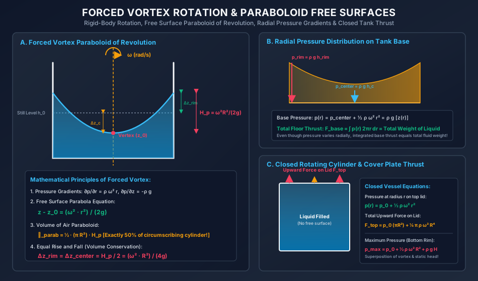
Diagram 2: Forced Vortex Rotation & Paraboloid Profiles
The following diagram demonstrates forced vortex rotation, the paraboloid of revolution, equal rim rise and central fall, radial pressure distribution on the bottom floor, and closed rotating cylinder cover thrust:
8. Worked Numerical Problems
Problem 1: Open Rectangular Tank Linear Acceleration & Spilling (GATE / ESE Standard)
Statement: An open rectangular tank of length , width , and height contains water to a depth of . The tank is accelerated horizontally along its length. Take and .
- Determine the maximum horizontal acceleration that can be applied without spilling water.
- If the tank is accelerated at , compute the volume of water spilled.
- For , calculate the total hydrostatic force on the rear wall () and front wall (), and verify Newton's second law.
Solution:
Part 1: Maximum Acceleration Without Spilling:
- Available freeboard:
- Rise at rear wall without spilling:
- Maximum acceleration:
Part 2: Volume Spilled at :
- Tilt angle of free surface:
- Since , water spills over the rear lip.
- Liquid depth at rear wall:
- Liquid depth at front wall:
- Because , the bottom floor remains completely covered with water (trapezoidal cross-section).
- Remaining water volume:
- Initial water volume:
- Volume of water spilled:
Part 3: Hydrostatic Wall Forces & Newton's Second Law Check:
- Hydrostatic force on rear wall:
- Hydrostatic force on front wall:
- Net horizontal fluid force:
- Theoretical inertial force ():
Problem 2: Open Cylindrical Tank Forced Vortex & Spilling (ESE / SSC JE Standard)
Statement: An open cylindrical tank of diameter (radius ) and height contains water to an initial depth of (freeboard ). The cylinder is rotated about its vertical axis of symmetry. Take and .
- Compute the maximum rotational speed (in ) without spilling water.
- Determine the rotational speed (in ) at which the vertex of the water paraboloid just touches the bottom of the cylinder, and the volume of water spilled at this stage.
- If the cylinder is rotated at (), calculate the radius of the dry circle formed on the base floor.
Solution:
Part 1: Maximum Speed Without Spilling:
- Available freeboard:
- In an unspilled tank, rise at rim equals freeboard:
- Rotational speed in :
Part 2: Speed to Just Touch Bottom Center ():
- When the vertex touches the bottom floor () and the water reaches the top rim (), the total height of the paraboloid is:
- At this stage, the volume of air inside the vessel is the volume of the paraboloid:
- Total cylinder volume:
- Remaining water volume:
- Initial water volume:
- Volume of water spilled:
Part 3: Dry Circle on Bottom Floor at :
- Paraboloid height at :
- Because , the imaginary vertex lies below the bottom floor:
- At the floor (), the radius of the dry circle satisfies:
Problem 3: Closed Rotating Cylindrical Vessel & Cover Plate Thrust (GATE Standard)
Statement: A closed cylindrical vessel of diameter (radius ) and height is completely filled with water. An initial static gauge pressure of is maintained at the top center of the cover plate. The vessel is rotated about its vertical central axis at . Take and .
- Determine the maximum pressure developed in the vessel and its location.
- Calculate the total upward hydrostatic force exerted on the top cover plate.
Solution:
Rotational Speed:
Part 1: Maximum Pressure: In a rotating closed vessel, pressure increases with:
- Radial distance from the axis (due to centrifugal effect: ).
- Vertical depth below the top cover (due to hydrostatic gravity: ). Therefore, the maximum pressure occurs at the bottom outer rim ():
- Initial top center pressure:
- Centrifugal pressure rise at outer rim:
- Hydrostatic gravity pressure head:
Total maximum pressure:
Part 2: Total Upward Force on Top Cover Plate (): The pressure on the top cover plate () at radius is:
Integrating over concentric rings of area :
- Static pressure force component:
- Dynamic vortex force component:
Total upward thrust:
9. Common Traps, Fallacies & Edge Cases
Trap 1: Confusing Paraboloid Volume with Cylinder Volume
- The Fallacy: Assuming that because the height of the paraboloid is , the volume of air inside is equal to .
- The Physical Reality: The volume of a paraboloid of revolution is exactly half (). Consequently, in an unspilled cylindrical vessel, the fall at the center equals the rise at the rim ().
Trap 2: Neglecting the Formation of a Dry Floor Patch
- The Fallacy: Applying even when .
- The Physical Reality: Once the vertex touches the floor (), the liquid cannot fall further at the center. Instead, a dry circle of radius forms on the floor, and fluid spills out. The standard 50% volume relation no longer applies directly without subtracting the truncated paraboloid.
Trap 3: Confusing Forced Vortex with Free Vortex
- The Fallacy: Assuming velocity in a forced vortex is inversely proportional to radius ().
- The Physical Reality:
- Forced Vortex: Fluid rotates as a solid body (). Vorticity is non-zero (). Driven by external torque (impellers, container walls).
- Free Vortex: Fluid rotates without external torque (). Vorticity is zero (, irrotational). Seen in bathtub drains and cyclones.
Trap 4: Assuming Net Horizontal Force on an Accelerated Tank is Zero
- The Fallacy: Believing that because the liquid is in static equilibrium relative to the tank, .
- The Physical Reality: The fluid mass is accelerating at . By Newton's second law, there must be a net force: . The difference in hydrostatic thrust between the deeper rear wall and shallower front wall provides this exact accelerating force!
10. Multi-Exam Multi-Choice & Conventional Practice Set
Q1. GATE CE (1 Mark) — Free Surface Shape in Forced Vortex
Question: The free surface of a liquid contained in an open cylindrical vessel rotating at a constant angular velocity about its vertical axis of symmetry takes the shape of a:
- (A) Circular cone
- (B) Paraboloid of revolution
- (C) Hemisphere
- (D) Hyperboloid of revolution
Solution: From radial equilibrium, . Integrating yields , which is the equation of a paraboloid of revolution. Correct Answer: (B)
Q2. UPSC ESE (Paper-II) — Free Surface Tilt in Accelerating Tank
Question: An open rectangular tank containing liquid is accelerated uniformly along a horizontal road at . Taking , the slope of the free liquid surface with the horizontal is:
- (A)
- (B)
- (C)
- (D)
Solution:
Correct Answer: (A)
Q3. SSC JE — Rim Rise vs Center Fall in Rotating Cylinder
Question: In an open cylindrical tank rotated at constant angular speed about its central vertical axis without spilling, the rise of liquid at the circumference compared to the depression at the axis of rotation is:
- (A) Twice as large
- (B) Equal
- (C) Half as large
- (D) Four times as large
Solution: Because the volume of a paraboloid of revolution is exactly half the circumscribing cylinder, volume conservation requires:
Correct Answer: (B)
Q4. State AE — Liquid in Free Fall
Question: If an open container containing water is allowed to fall freely under gravity (), the pressure at any depth below the free surface is:
- (A) Equal to
- (B) Equal to
- (C) Zero gauge pressure throughout
- (D) Infinitely large
Solution: The effective gravity is . The hydrostatic pressure gradient is . Hence, the gauge pressure is identically zero throughout the liquid mass. Correct Answer: (C)
Q5. RRB JE — Centrifugal Pressure Rise
Question: The pressure rise from the center () to the outer rim () on the flat top cover of a closed cylindrical tank rotated at angular velocity is:
- (A)
- (B)
- (C)
- (D)
Solution: Integrating from to at constant elevation gives:
Correct Answer: (B)
11. Cross-Subject Synthesis & Practical Field Applications
1. Transportation Engineering: Road Tanker Sloshing & Baffle Design
Highway liquid cargo tankers (transporting fuel, milk, or chemicals) experience substantial longitudinal decelerations during emergency braking (). Unbaffled tanks suffer catastrophic dynamic free surface tilt, transferring massive kinetic energy to the front bulkhead. Engineers install transverse perforated baffles to dampen sloshing and maintain vehicular braking stability.
2. Environmental & Water Engineering: Centrifugal Grit Separators & Hydrocyclones
Municipal sewage treatment plants use vortex grit chambers and hydrocyclones where rotating liquid fields generate forced vortex acceleration profiles. Dense sand particles experience strong outward centrifugal forces (), separating them efficiently from organic suspended solids.
3. Structural Concrete Manufacturing: Centrifugal Spinning of RCC Pipes
In the production of precast Hume pipes (IS 458), fresh concrete slurry is fed into rapidly rotating cylindrical steel molds. Centrifugal acceleration () forces dense aggregate and cement mortar against the outer mold wall while expelling excess mixing water toward the inner core, producing high-density, impervious concrete with compressive strengths exceeding .
12. Comprehensive Summary & Formula Cheatsheet
Quick Revision Cards
================================================================================
           RELATIVE EQUILIBRIUM: LINEAR ACCEL & FORCED VORTEX CHEATSHEET
================================================================================

1. GENERAL RELATIVE EQUILIBRIUM:
   - No relative motion -> Velocity gradient du/dy = 0 -> Shear stress τ = 0
   - Navier-Stokes reduces to: ∇p = ρ(g - a)
   - Isobars & Free Surfaces: dp = 0 -> -ρ ax dx - ρ ay dy - ρ(g + az) dz = 0

2. UNIFORM LINEAR ACCELERATION:
   - Horizontal Accel (ax): Free surface slope tan θ = ax / g
   - Combined 2D Accel:      tan θ = ax / (g ± az)   [+ for up, - for down]
   - Free Fall (az = -g):    g_eff = 0 -> Zero pressure gradient throughout!
   - Unspilled Depths:       h_rear = h0 + (L/2) tan θ,  h_front = h0 - (L/2) tan θ
   - Max Accel (No Spill):   ax_max = (2 f g) / L  where f = H - h0 (freeboard)
   - Dynamic Force Balance:  F_rear - F_front = m_liquid · ax  (Newton's 2nd Law)

3. FORCED VORTEX ROTATION (CYLINDRICAL TANK):
   - Particle velocity: v = ω r (Rotational flow, vorticity ζ = 2ω ≠ 0)
   - Pressure gradients: ∂p/∂r = ρ ω² r,   ∂p/∂z = -ρ g
   - Free Surface Shape: Paraboloid of Revolution: z - z0 = (ω² r²) / (2g)
   - Total Paraboloid Height: H_p = (ω² R²) / (2g)
   - Paraboloid Volume: ∀_parab = ½ (π R²) H_p  (Exactly 50% of cylinder!)
   - Equal Rise and Fall: Δz_rim = Δz_center = H_p / 2 = (ω² R²) / (4g)
   - Speeds:
     * No spill:    ω_spill = (2 / R) √(g f)
     * Touch floor: ω_touch = √(2g H) / R   [Remaining volume = 50% of tank]
     * Dry floor:   r0 = √(R² - 2gH / ω²)

4. CLOSED ROTATING CYLINDER:
   - Top lid pressure: p_top(r) = p0 + ½ ρ ω² r²
   - Upward force on lid: F_top = p0(π R²) + ¼ π ρ ω² R⁴
   - Max pressure (bottom rim): p_max = p0 + ½ ρ ω² R² + ρ g H
================================================================================
References & Standard Codes
- Streeter, V. L., Wylie, E. B., and Bedford, K. W., Fluid Mechanics, 9th Edition, McGraw-Hill, New York.
- White, F. M., Fluid Mechanics, 8th Edition, McGraw-Hill Education, 2016.
- Modi, P. N., and Seth, S. M., Hydraulics and Fluid Mechanics Including Hydraulics Machines, Standard Book House, New Delhi.
- Fox, R. W., McDonald, A. T., and Pritchard, P. J., Introduction to Fluid Mechanics, 8th Edition, John Wiley & Sons.
- IS 458:2003, Precast Concrete Pipes (With and Without Reinforcement) - Specification, Bureau of Indian Standards.