Moment of Momentum Equation, Rotating Fluid Machinery & Lawn Sprinklers
In this chapter (4 topics)
On this page
- 1. Topic Metadata Table
- 2. Executive Summary
- 3. Angular Momentum Flux & Control Volume Moment of Momentum Theorem
- 3.1 Formal Derivation from Reynolds Transport Theorem
- 3.2 Scalar Component about the Axis of Rotation
- 4. Rotary Reaction Lawn Sprinklers: Kinematics & Operational Regimes
- 4.1 State 1: The Sprinkler is Held Stationary (ω = 0)
- 4.2 State 2: Free Rotation with Zero Bearing Friction (Text = 0)
- 4.3 State 3: Rotation with Resisting Bearing Friction (Tf > 0)
- 5. Euler Turbomachine Equation for Pumps & Compressors (Energy Input)
- 5.1 Formulation of Shaft Torque and Work
- 5.2 Euler Head (He) Imparted to the Fluid
- 5.3 Condition of Radial Inlet in Centrifugal Pumps (Vw1 = 0)
- 6. Euler Turbomachine Equation for Reaction Turbines (Energy Extraction)
- 6.1 Runner Torque and Power Output
- 6.2 Euler Turbine Head (He)
- 6.3 Maximum Turbine Efficiency Condition: Zero Whirl at Exit (Vw2 = 0)
- 7. Free Vortex vs Forced Vortex Flow: Angular Momentum Conservation Perspective
- 1. Free Vortex Motion (Σ Text = 0)
- 2. Forced Vortex Motion (Σ Text ≠ 0)
- 8. Visual Diagrams & Architectural Schematics
- 8.1 Reaction Lawn Sprinkler Kinematics & Angular Momentum Regimes
- 8.2 Turbomachine Velocity Triangles: Centrifugal Pump vs Francis Turbine
- 9. Step-by-Step Numerical Problems with Complete Calculations
- Problem 1: Rotating Lawn Sprinkler — Holding Torque, Free Runaway Speed & Bearing Friction
- Problem 2: Centrifugal Pump Impeller — Velocity Triangles, Torque, Power & Euler Head
- Problem 3: Inward-Flow Francis Reaction Turbine — Runner Torque, Power & Euler Head
- 10. High-Yield Exam Pitfalls, Traps & Shortcuts
- 11. Multi-Exam Question Bank (GATE, ESE, SSC JE, State AE, RRB JE)
- Question 1 (GATE CE — Multiple Choice Question)
- Question 2 (UPSC ESE Paper-II)
- Question 3 (SSC JE)
- Question 4 (State PSC AE)
- Question 5 (RRB JE)
- 12. Comprehensive Summary, Formula Cheatsheet & Academic References
- Master Formula Cheatsheet
- Academic References & Standard Source Texts
1. Topic Metadata Table
| Field | Detail |
|---|---|
| Subject | Fluid Mechanics & Hydraulic Machinery (Subject 07) |
| Chapter | Chapter 04: Fluid Dynamics & Momentum Equation |
| Topic Code | FM-04-04 |
| Topic Title | Moment of Momentum Theorem, Angular Momentum Flux, Rotary Reaction Lawn Sprinklers (Stationary vs Free vs Friction), Euler Turbomachine Equation (Pumps & Turbines) & Velocity Triangles |
| Prerequisites | FM-03-04 (Vorticity, Rotation, Forced vs Free Vortex), FM-04-01 (Bernoulli's Equation & Head), FM-04-03 (Control Volume Linear Momentum Equation) |
| Target Examinations | GATE CE, UPSC ESE (Paper-II), SSC JE, State PSC AE/JE, RRB JE |
| Knowledge Level | Angular Continuum Mechanics to Core Turbomachinery Energy Transfer Theory |
| IS / IEC / Standard Codes | IS 9137 (Code for acceptance tests for centrifugal, mixed flow and axial pumps - Class C), IS 12800 (Guidelines for selection of hydraulic turbines), IEC 60193 (Hydraulic turbines, storage pumps and pump-turbines - Model acceptance tests) |
| Key Formulae | , , , , (Pump), (Turbine), |
2. Executive Summary
While linear momentum conservation determines external resultant forces on static fluid boundaries, dynamic energy exchange in rotating fluid machinery (rotodynamic pumps, Francis/Kaplan water turbines, torque converters, and reaction lawn sprinklers) is governed by the Moment of Momentum Theorem (Angular Momentum Conservation). Derived by applying the moment of Newton's second law () to a control volume via the Reynolds Transport Theorem, the net external torque acting on a fluid within a fixed control volume under steady flow conditions identically equals the net efflux rate of angular momentum across its control surfaces:
For axisymmetric rotating runners where inflow occurs at radius and outflow at radius , the scalar torque about the axis of rotation reduces to the foundational relationship:
where represents the Whirl Velocity (the tangential component of absolute fluid velocity).
Key applications and behavioral laws:
- The Rotary Reaction Lawn Sprinkler:
- Operating via reaction thrust from oppositely directed tangential nozzles (), the sprinkler exhibits three distinct states:
- Held Stationary (): Absolute whirl equals relative velocity (). The resisting torque required to hold it stationary is maximum: .
- Free-Spinning (Zero Bearing Friction, ): The steady-state net torque is zero. The exiting fluid has zero absolute whirl (). The rotor spins at its terminal runaway speed: .
- Loaded / Bearing Friction (): Resisting friction torque retards the rotor speed linearly: .
- Operating via reaction thrust from oppositely directed tangential nozzles (), the sprinkler exhibits three distinct states:
- The Euler Turbomachine Equation:
- Connecting fluid kinematics directly to power generation and absorption:
- Power:
- Euler Head ():
- For Centrifugal Pumps, mechanical energy is delivered to the water (); radial entry () maximizes head.
- For Hydraulic Turbines (Francis, Kaplan), energy is extracted from the water (); maximum hydraulic efficiency is achieved when the discharge is purely radial/axial without residual whirl ().
- Connecting fluid kinematics directly to power generation and absorption:
- Vortex Flow Dynamics Revisited:
- In a Free Vortex, external torque is zero (); hence, angular momentum is conserved along streamlines: .
- In a Forced Vortex, external torque is continuously applied by a motor-driven impeller (); hence, solid-body rotation prevails: .
3. Angular Momentum Flux & Control Volume Moment of Momentum Theorem
3.1 Formal Derivation from Reynolds Transport Theorem
Let be the total angular momentum (moment of momentum) of a fluid system about a fixed coordinate origin :
The intensive property (angular momentum per unit mass) is:
Newton's second law for angular motion states that the net external torque acting on the system equals the time rate of change of its total angular momentum:
Applying the Reynolds Transport Theorem for a fixed spatial Control Volume (CV):
For steady flow (), the internal rate of angular momentum accumulation is identically zero:
3.2 Scalar Component about the Axis of Rotation
In turbomachinery, rotation occurs about a designated principal axis (take the -axis). In cylindrical polar coordinates , the velocity vector is:
The position vector from the axis of rotation is . Taking the cross product:
Evaluating the -component (parallel to the rotation axis):
where is the Whirl Velocity (the circumferential/tangential velocity component perpendicular to the radius). Therefore, the scalar torque acting about the rotation axis is:
For uniform 1D streams across inlet Section 1 and outlet Section 2:
4. Rotary Reaction Lawn Sprinklers: Kinematics & Operational Regimes
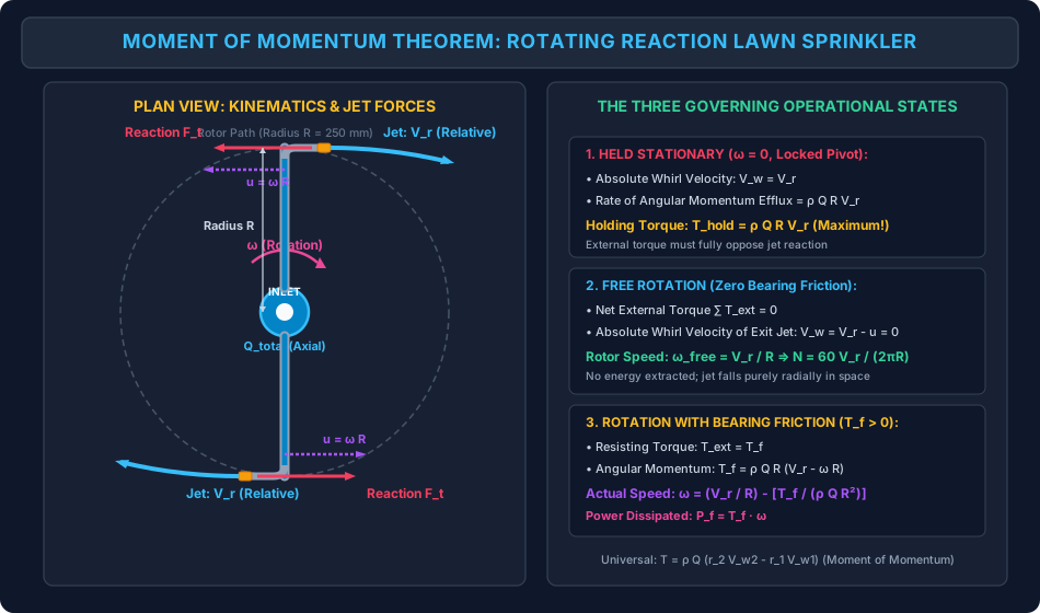
A classic reaction lawn sprinkler consists of two (or more) horizontal hollow symmetrical tubular arms of radius rotating in a horizontal plane about a central vertical water supply pivot.
- Each arm terminates in a nozzle of exit area discharging liquid at an angle (most commonly tangential, ).
- Total discharge entering the central hub: .
- Discharge per arm: (for a 2-armed sprinkler, ).
- Nozzle exit relative velocity:
                Top View of 2-Armed Reaction Sprinkler:
                          Arm 1
               Reaction <====== [Nozzle 1] ===> Jet V_r (Exit)
                  F_t            |
                                 | R (Radius)
                                 O (Pivot Hub)
                                 | R (Radius)
                                 |
        Jet V_r (Exit) <=== [Nozzle 2] ======> Reaction
                                                F_t
When the rotor spins at an angular velocity (counter-clockwise), the tip of each arm moves with a tangential peripheral blade speed:
Because the jet discharges in the direction opposite to the arm's motion (reaction propulsion), the Absolute Whirl Velocity () of the exiting fluid jet in the stationary laboratory reference frame is:
Applying the moment of momentum equation between the central supply pivot () and the nozzle exits ():
4.1 State 1: The Sprinkler is Held Stationary ()
If an external clamp or mechanical brake prevents the sprinkler from rotating ():
- Peripheral speed .
- The absolute exit velocity equals the relative velocity: .
- The fluid leaves with maximum angular momentum flux: .
- To keep the sprinkler stationary, the holding clamp must exert a Resisting Holding Torque: (This is the maximum possible torque the sprinkler can ever exert).
4.2 State 2: Free Rotation with Zero Bearing Friction ()
If the sprinkler rotates freely on an ideal, frictionless bearing without any external mechanical load:
- The net external torque is zero: .
- The moment of momentum equation requires:
- Therefore, the absolute whirl velocity of the exiting jet is exactly zero ()! (The jet exits the nozzle at speed relative to the arm, but because the arm is retreating at speed , the water drops vertically into space with zero tangential velocity!)
- The free-spinning runaway angular velocity is:
- Rotational speed in revolutions per minute ():
4.3 State 3: Rotation with Resisting Bearing Friction ()
In real mechanical sprinklers, bearing seal friction, mechanical drag, and air resistance impose a resisting friction torque :
Solving for the actual operational angular velocity :
- Mechanical power dissipated by friction:
5. Euler Turbomachine Equation for Pumps & Compressors (Energy Input)
In rotodynamic machines (centrifugal pumps, mixed-flow pumps, and centrifugal compressors), an external driver (electric motor) imparts mechanical torque to an impeller, transferring energy to the flowing fluid.
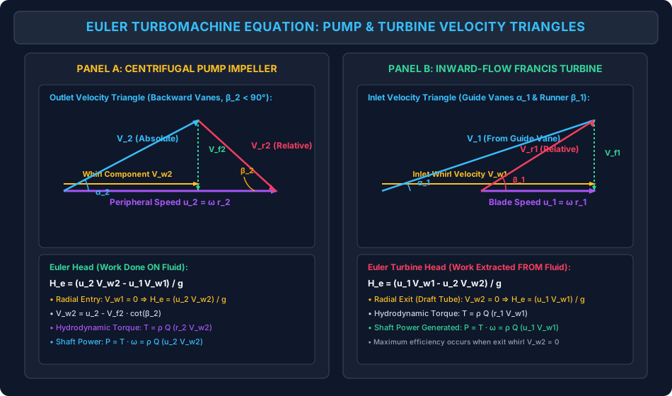
       Impeller Blade Profile:
                                Outlet (r2, u2, V2, Vr2)
                                 /|
                                / | V_f2
                               /  |
        Inlet (r1, u1, V1)   /   +------------
              \             /    <-- V_w2 --->
               \___________/     <------ u2 ------->
5.1 Formulation of Shaft Torque and Work
Applying the moment of momentum equation across the impeller from inlet (1) to outlet (2):
Multiplying by the impeller angular velocity :
Noting that peripheral blade speed is :
5.2 Euler Head () Imparted to the Fluid
The mechanical energy added to the fluid per unit weight is the Euler Head (, in meters of fluid):
5.3 Condition of Radial Inlet in Centrifugal Pumps ()
Centrifugal pumps are designed so that fluid enters the impeller eye purely axially and turns into the radial plane without any pre-whirl:
Under this standard design condition, the Euler pump equation simplifies to:
From the outlet velocity triangle with backward-curved blades ():
Substituting into the Euler head equation:
This quadratic-to-linear relationship explains why backward-curved vanes () exhibit a declining head-capacity curve (), ensuring self-regulating hydraulic stability and preventing motor overload.
6. Euler Turbomachine Equation for Reaction Turbines (Energy Extraction)
In hydraulic turbines (Francis, Kaplan, and Pelton wheels), high-pressure water delivers mechanical energy to the runner, driving an electrical generator.
6.1 Runner Torque and Power Output
Because the fluid does work on the runner, the angular momentum decreases from inlet (1) to outlet (2):
Turbine shaft power generated:
6.2 Euler Turbine Head ()
The total head extracted from the water by the turbine runner is:
6.3 Maximum Turbine Efficiency Condition: Zero Whirl at Exit ()
Any residual tangential whirl velocity () at the runner outlet represents unrecovered kinetic energy () discharged into the tailrace. Therefore, all modern reaction turbines (Francis and Kaplan) are designed such that at design discharge, water exits the runner purely axially/radially:
Under this optimal condition:
7. Free Vortex vs Forced Vortex Flow: Angular Momentum Conservation Perspective
The moment of momentum theorem provides the fundamental unifying physics explaining vortex motions previously introduced in kinematics (FM-03-04):
1. Free Vortex Motion ()
- In a free vortex (such as flow into a sink, a bathtub drain, or a river whirlpool outside the viscous core), no external torque acts on fluid elements ().
- Therefore, the moment of momentum about the axis of rotation is strictly conserved:
- Velocity increases hyperbolically toward the center ( as ).
- Total mechanical energy head is constant across all streamlines: . The flow is irrotational ().
2. Forced Vortex Motion ()
- In a forced vortex (such as liquid rotated inside a cylindrical vessel by an impeller or stirrer), external torque is continuously applied to fluid particles via viscous shear from the rotating walls.
- Every fluid particle rotates with identical angular velocity :
- The angular momentum per unit mass increases quadratically with radius: .
- The total energy head increases radially (). The flow is rotational with uniform vorticity .
8. Visual Diagrams & Architectural Schematics
8.1 Reaction Lawn Sprinkler Kinematics & Angular Momentum Regimes
The schematic below details the geometry and kinematics of a two-armed reaction lawn sprinkler, contrasting relative velocity, peripheral blade speed, and the three distinct operational regimes.
8.2 Turbomachine Velocity Triangles: Centrifugal Pump vs Francis Turbine
The multi-panel diagram below displays the inlet and outlet velocity triangles, whirl components, and Euler energy exchange formulations for both energy-absorbing (pumps) and energy-extracting (turbines) rotodynamic machinery.
9. Step-by-Step Numerical Problems with Complete Calculations
Problem 1: Rotating Lawn Sprinkler — Holding Torque, Free Runaway Speed & Bearing Friction
Problem Statement: A symmetrical two-armed garden reaction lawn sprinkler has arms of length .
- Each arm terminates in a circular nozzle of exit diameter .
- The nozzles discharge water () tangentially in opposite directions.
- Total water discharge supplied through the central pivot: ( per nozzle).
- Neglect fluid friction within the pipe arms.
Determine:
- Nozzle exit relative velocity in ,
- Resisting torque required to hold the sprinkler stationary (),
- Maximum free-spinning rotational speed in and in assuming zero bearing friction,
- Rotational speed and in if mechanical bearing friction exerts a resisting torque .
Solution & Step-by-Step Calculation:
Step 1: Compute nozzle cross-sectional area and exit relative velocity Nozzle diameter: .
Discharge per nozzle:
Relative exit velocity:
Step 2: Resisting torque to hold the sprinkler stationary () When , the peripheral speed , so absolute whirl velocity is . Angular momentum equation about the central pivot:
Step 3: Free-spinning runaway rotational speed (zero bearing friction) For free steady rotation with :
Rotational speed in :
Step 4: Rotational speed with bearing friction torque
Rotational speed in :
(Bearing friction of retards rotor speed from down to ).
Problem 2: Centrifugal Pump Impeller — Velocity Triangles, Torque, Power & Euler Head
Problem Statement: A centrifugal water pump impeller rotates at a constant speed of .
- Impeller eye inlet radius: .
- Impeller outer tip radius: .
- Water flow rate through the pump: ().
- Water enters the impeller vanes purely radially without pre-whirl ().
- The impeller vanes are curved backward with an exit vane angle .
- The radial velocity of flow is constant from inlet to outlet: .
- Density of water: .
Determine:
- Impeller angular velocity and peripheral blade speeds and ,
- Absolute whirl velocity and absolute exit velocity at the outlet,
- Hydrodynamic torque exerted on the water by the impeller,
- Theoretical shaft power required to drive the impeller in ,
- Euler head developed by the pump in meters of water.
Solution & Step-by-Step Calculation:
Step 1: Compute angular velocity and peripheral blade speeds
Inlet blade speed:
Outlet blade speed:
Step 2: Outlet Velocity Triangle and Whirl Component For backward-curved vanes ():
Absolute velocity at outlet:
Step 3: Hydrodynamic Torque Exerted by Impeller on Water Since water enters radially, :
Step 4: Shaft Power Required
Step 5: Euler Head ()
Problem 3: Inward-Flow Francis Reaction Turbine — Runner Torque, Power & Euler Head
Problem Statement: An inward-flow Francis reaction hydraulic turbine runner operates at a rotational speed of .
- Outer runner diameter (inlet): .
- Inner runner diameter (outlet): .
- Volumetric discharge of water through the turbine: ().
- The water leaves the stationary guide vanes at an angle to the tangential direction.
- Radial flow velocity at the runner inlet: .
- The water discharges from the runner into the draft tube purely radially without any residual whirl ().
- Water density .
Determine:
- Runner angular velocity and inlet blade peripheral speed ,
- Absolute whirl velocity and absolute inlet velocity ,
- Hydrodynamic torque exerted by the water on the turbine runner in ,
- Shaft power generated by the runner in and ,
- Euler turbine head extracted from the water.
Solution & Step-by-Step Calculation:
Step 1: Compute angular velocity and inlet blade peripheral speed
Step 2: Inlet Velocity Triangle and Whirl Component From the inlet velocity triangle with guide vane angle :
Absolute inlet velocity:
Step 3: Hydrodynamic Torque Exerted by Water on Runner Because discharge is purely radial ():
Step 4: Shaft Power Generated
Step 5: Euler Turbine Head ()
10. High-Yield Exam Pitfalls, Traps & Shortcuts
-
Free Sprinkler Velocity Fallacy (GATE & ESE):
- Trap: Thinking the absolute velocity of the jet leaving a free-spinning sprinkler is .
- Truth: In free rotation with zero friction, the sprinkler accelerates until the absolute whirl velocity is zero (). The water jet simply drops straight down in the stationary reference frame!
-
Pump vs Turbine Sign Convention in Euler Equation:
- Centrifugal Pump (Work absorbed by fluid):
- Hydraulic Turbine (Work extracted from fluid):
- Memory Rule: "High energy minus low energy" keeps positive.
-
Radial Entry and Radial Exit Conditions:
- In a pump, radial entry means .
- In a turbine, radial exit means .
- This eliminates the second term in the Euler equation!
-
Sprinkler Torque with Nozzle Inclination:
- If nozzles are tilted at an angle to the tangent:
-
Whirl Velocity vs Relative Velocity vs Flow Velocity:
- Whirl velocity : Tangential component of absolute velocity (produces torque).
- Flow velocity : Radial component of absolute velocity (carries discharge: ).
- Relative velocity : Velocity along the blade surface in rotating frame.
11. Multi-Exam Question Bank (GATE, ESE, SSC JE, State AE, RRB JE)
Question 1 (GATE CE — Multiple Choice Question)
A lawn sprinkler with two identical arms of radius discharges water through two nozzles of area each. The nozzles discharge tangentially. If a total discharge of is supplied to the sprinkler, the runaway rotational speed in assuming zero bearing friction is:
- A)
- B)
- C)
- D)
Detailed Solution: Total discharge . Discharge per nozzle . Area per nozzle . Relative exit velocity:
Free runaway angular velocity:
Rotational speed in :
Matching option B. Correct Answer: B
Question 2 (UPSC ESE Paper-II)
In a centrifugal pump, maximum theoretical head is developed when water enters the impeller:
- A) Tangentially in the direction of rotation
- B) Radially without whirl ()
- C) Tangentially against the direction of rotation ()
- D) At an angle of to the blade
Detailed Solution: Euler head for a pump is . If water has a negative pre-whirl (, against rotation), the term becomes positive, increasing . However, in standard pump design, radial entry () is chosen to minimize shock losses and provide stable operation without prerotation. For standard designed pumps, radial inlet gives . Correct Answer: B
Question 3 (SSC JE)
The Euler turbine equation for a hydraulic turbine relates:
- A) Discharge to head loss
- B) Torque and power to the rate of change of angular momentum
- C) Pressure head to velocity head along a streamline
- D) Critical shear stress to boundary layer thickness
Detailed Solution: The Euler turbine equation is derived from the moment of momentum theorem and equates shaft torque and power to the net rate of change of angular momentum of fluid passing through the runner: . Correct Answer: B
Question 4 (State PSC AE)
If a two-armed lawn sprinkler discharging water at relative velocity from radius is prevented from rotating, the holding torque required is:
- A) Zero
- B)
- C)
- D)
Detailed Solution: When stationary (), . The rate of efflux of angular momentum is . The holding torque must balance this exactly: . Correct Answer: C
Question 5 (RRB JE)
For a Francis reaction turbine, maximum hydraulic efficiency is obtained when:
- A) The water leaves the runner with maximum whirl velocity
- B) The absolute velocity at exit is purely radial ()
- C) The guide vane angle is
- D) The blade angle at inlet is
Detailed Solution: When water discharges from the runner purely radially (), no kinetic whirl energy is wasted in the tailrace, maximizing energy conversion in the runner. Correct Answer: B
12. Comprehensive Summary, Formula Cheatsheet & Academic References
Master Formula Cheatsheet
Academic References & Standard Source Texts
- White, F. M. (2016). Fluid Mechanics (8th ed.). McGraw-Hill Education. Chapter 3: Integral Relations for a Control Volume (Section 3.5: The Angular-Momentum Theorem); Chapter 11: Turbomachinery.
- Modi, P. N., & Seth, S. M. (2018). Hydraulics and Fluid Mechanics Including Hydraulics Machines (22nd ed.). Standard Book House, New Delhi. Chapter 8: Momentum and Angular Momentum; Chapter 18: Centrifugal Pumps; Chapter 19: Hydraulic Turbines.
- Streeter, V. L., Wylie, E. B., & Bedford, K. W. (1998). Fluid Mechanics (9th ed.). WCB/McGraw-Hill. Chapter 11: Turbomachinery.
- Rajput, R. K. (2020). A Textbook of Fluid Mechanics and Hydraulic Machines (7th ed.). S. Chand & Company Ltd. Chapter 18: Centrifugal Pumps; Chapter 20: Water Turbines.
- IS 9137: Code for Acceptance Tests for Centrifugal, Mixed Flow and Axial Pumps. Bureau of Indian Standards, New Delhi.
- IEC 60193: Hydraulic Turbines, Storage Pumps and Pump-Turbines - Model Acceptance Tests. International Electrotechnical Commission.