Plastic Analysis of Portal Frames (Combined & Sway Mechanisms)
In this chapter (4 topics)
On this page
- 1. Introduction & Conceptual Foundations
- 2. Degrees of Freedom, Indeterminacy & Mechanism Counting
- 2.1 Fixed-Base vs. Pinned-Base Rectangular Portal Frames
- 3. Independent Mechanism Decomposition for Rectangular Frames
- 3.1 Mode 1: Beam Mechanism (Nb)
- 3.2 Mode 2: Sway (Panel) Mechanism (Ns)
- 4. Combined Mechanisms & The Principle of Corner Hinge Cancellation
- 4.1 Kinematic Superposition & Corner Cancellation
- 4.2 Energy Dissipation in the Combined Mechanism (Fixed Base)
- 5. Mechanism Interaction Diagrams (Failure Envelopes)
- 5.1 Boundary Equations (Fixed-Base Frame)
- 5.2 Geometry of the Failure Envelope
- 6. Pitched-Roof (Gable) Portal Frames: Instantaneous Center Method
- 6.1 The Instantaneous Center of Rotation (IC)
- 6.2 Kinematic Relations via IC
- 6.3 Work Balance for Gable Frame under Ridge Load W
- 7. Worked Numerical Examples
- Problem 1: Pinned-Base (Two-Hinged) Portal Frame (Beam vs. Sway vs. Combined)
- Problem 2: Fixed Portal Frame with Unequal Column Heights
- Problem 3: Pitched-Roof (Gable) Portal Frame under Vertical Ridge Load
- 8. Common Misconceptions & Exam Pitfalls
- 9. Comparative Summary & Formula Matrix
- 10. Practice Questions & Competitive Examination Problems
- Multiple Choice & Objective Questions
- 11. References & Code Standards
1. Introduction & Conceptual Foundations
Portal frames constitute the primary lateral and gravity load-resisting skeletal system in industrial sheds, warehouses, sports arenas, and low-rise commercial structures. Under elastic design (ASD/WSM), internal forces in portal frames are heavily influenced by foundation fixity, column-to-beam stiffness ratios (), and thermal/settlement effects.
In contrast, Plastic Analysis evaluates the ultimate capacity of portal frames at impending collapse. In plastic theory:
- Elastic stiffness ratios become irrelevant at the plastic limit state; capacity is governed solely by the plastic moment capacities () of the columns and girders.
- Foundation settlement and residual stresses do not alter the plastic collapse load (provided ductility is sufficient).
- Complex framed structures collapse along one of several distinct kinematic modes: Beam Mechanisms, Sway (Panel) Mechanisms, Joint Mechanisms, or Combined Mechanisms.
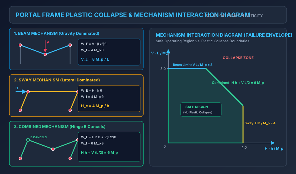
   Frame Loading System (Gravity V + Lateral H)
      |
      +---> Beam Mechanism (Span yields under V; lateral sway = 0)
      |
      +---> Sway Mechanism (Columns drift under H; beam does not sag)
      |
      +---> Combined Mechanism (Beam sag + Column drift; Hinge at corner cancels!)
            ===> ALMOST ALWAYS GOVERNS FOR COMBINED GRAVITY + LATERAL LOADS
2. Degrees of Freedom, Indeterminacy & Mechanism Counting
For any planar skeletal frame:
where:
- is the degree of static indeterminacy under planar loading.
- is the number of candidate plastic hinge locations.
- is the dimension of the independent mechanism basis.
2.1 Fixed-Base vs. Pinned-Base Rectangular Portal Frames
| Parameter | Fixed-Base Portal Frame (Rigid Foundations) | Pinned-Base Portal Frame (Two-Hinged Frame) |
|---|---|---|
| Support Reactions | 6 reactions ( and ) | 4 reactions ( and ) |
| Static Indeterminacy () | ||
| Hinges at Column Bases | Possible (Hinges form at bases A and D) | Impossible (Bases are frictionless pins, ) |
| Total Candidate Hinges () | (A, B, E, C, D) | (B, E, C) |
| Independent Mechanisms () | ||
| Independent Modes | 1 Beam Mech + 1 Sway Mech | 1 Beam Mech + 1 Sway Mech |
| Collapse Hinges Needed () |
3. Independent Mechanism Decomposition for Rectangular Frames
Consider a single-bay rectangular portal frame ABCD with column height , beam span , carrying horizontal lateral force at joint B and concentrated gravity load at beam mid-span E.
3.1 Mode 1: Beam Mechanism ()
- Plastic hinges form within the beam: at joint B, mid-span E, and joint C.
- The columns remain vertical; no lateral displacement occurs ().
- Mid-span deflection: .
- Rotations: .
- Work Equation: Equating :
3.2 Mode 2: Sway (Panel) Mechanism ()
- The columns drift laterally by .
- The beam BC translates as a rigid body without bending ().
- For Fixed Bases: Plastic hinges form at A, B, C, and D:
- For Pinned Bases: Plastic hinges form only at column tops B and C (bases A and D rotate freely):
4. Combined Mechanisms & The Principle of Corner Hinge Cancellation
When a frame is subjected simultaneously to lateral wind/seismic load and vertical gravity load , the beam mechanism and sway mechanism interact kinematically.
4.1 Kinematic Superposition & Corner Cancellation
- In the Sway Mechanism: Column AB rotates clockwise by . This causes the top of column AB at joint B to rotate clockwise by .
- In the Beam Mechanism: Segment BE rotates counter-clockwise by to accommodate mid-span downward sag.
- At the rigid corner joint B: The plastic hinge at joint B completely vanishes!
- At the opposite corner joint C: The hinge rotations reinforce each other.
4.2 Energy Dissipation in the Combined Mechanism (Fixed Base)
- Plastic hinges form at: Base A (), Mid-span E (), Corner C (), Base D ().
- Total Internal Plastic Work: (Notice that without cancellation, would have been . Cancellation saves of plastic work!)
- Total External Work:
- Virtual Work Balance:
- For a Pinned-Base Frame (no hinges at A and D):
5. Mechanism Interaction Diagrams (Failure Envelopes)
The safe load domain for a portal frame subjected to independent variable loads and is represented in a two-dimensional Mechanism Interaction Diagram:
- Horizontal Axis: Normalized lateral load .
- Vertical Axis: Normalized gravity load .
5.1 Boundary Equations (Fixed-Base Frame)
- Beam Boundary:
- Sway Boundary:
- Combined Boundary:
5.2 Geometry of the Failure Envelope
- When : .
- When : .
- The failure envelope forms a convex polygon connecting vertices:
- Convexity Postulate (Drucker's Stability Postulate): The failure surface in load space is strictly convex. Any point inside the polygon represents a statically safe state. Any point outside represents plastic collapse.
6. Pitched-Roof (Gable) Portal Frames: Instantaneous Center Method
Pitched-roof (gable) frames introduce non-orthogonal geometry where rafters slope upwards toward a central apex (ridge point C).
                      Ridge C (Apex)
                         /\
           Rafter BC    /  \    Rafter CD
                       /    \
            Eaves B +--      --+ Eaves D
                    |          |
          Column AB |          | Column DE
                    |          |
            Base A /|/|/    /|/|/ Base E
6.1 The Instantaneous Center of Rotation (IC)
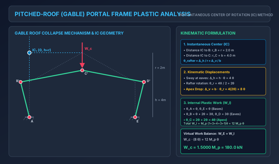
In a gable collapse mechanism, rafters BC and CD undergo general planar motion (simultaneous translation and rotation). To relate linear displacements of load points to angular hinge rotations, the Instantaneous Center of Rotation () is determined:
- The base of column AB rotates about fixed foundation A Joint B moves horizontally to the right:
- By symmetry under vertical ridge loading, the ridge point C moves strictly vertically downward:
- Locating for Rafter BC:
- Draw a line perpendicular to the displacement vector of B (a vertical line through joint B).
- Draw a line perpendicular to the displacement vector of C (a horizontal line through ridge C).
- The intersection point of these two perpendiculars is the Instantaneous Center (): where is column height and is roof rise ().
6.2 Kinematic Relations via
- Distance from to Joint B:
- Distance from to Ridge C:
- Angular rotation of rafter BC ():
- Vertical downward displacement of apex C ():
6.3 Work Balance for Gable Frame under Ridge Load
- External Work:
- Hinge Rotations:
- Fixed base A:
- Eaves B:
- Apex C:
- By symmetry:
- Total Internal Work:
- Collapse Load:
7. Worked Numerical Examples
Problem 1: Pinned-Base (Two-Hinged) Portal Frame (Beam vs. Sway vs. Combined)
Statement: A rectangular two-hinged portal frame ABCD has pinned bases at A and D (). Column height , beam span . Plastic moment capacity is uniform throughout. The frame carries a horizontal lateral load at joint B and a concentrated vertical load at the center of beam BC (point E).
- Calculate the collapse load for the Beam Mechanism.
- Calculate the collapse load for the Sway Mechanism.
- Calculate the collapse load for the Combined Mechanism.
- Determine the true collapse load and verify that the unyielded joint B does not violate the yield condition.
Solution:
Step 1: Mechanism 1 — Beam Mechanism
- Hinges form at joint B, mid-span E, and joint C:
- Columns remain vertical: .
- Deflection under load : .
- Rotations: .
- .
- .
- Equating :
- For :
Step 2: Mechanism 2 — Sway Mechanism
- Frame sways rightward by .
- Bases A and D are real pins (); hinges form only at column tops B and C:
- Rotations: .
- .
- .
- Equating :
- For :
Step 3: Mechanism 3 — Combined Mechanism
- Sway rotation and beam rotation cancel each other at corner joint B ().
- Plastic hinges form at:
- Mid-span E:
- Corner C:
- External Work:
- Internal Plastic Work:
- Equating :
- For :
Step 4: Governing Collapse Load & Statics Verification at Joint B
The Combined Mechanism governs at .
Statics Check at Unyielded Joint B:
- Column CD: Hinge at top C (), base D is pinned ().
- Horizontal equilibrium of the entire frame:
- Column AB (pinned base A, ):
- Check Yield Condition: The bending moment at joint B is of , strictly satisfying the yield criterion! Therefore, by the Uniqueness Theorem, is the exact collapse load.
Problem 2: Fixed Portal Frame with Unequal Column Heights
Statement: A rectangular portal frame ABCD has fixed bases at A and D. Column AB has height , while column CD has height . Beam BC has span . Plastic capacity is uniform throughout. A lateral load acts at joint B, and a vertical load acts at mid-span of beam BC. Determine the governing plastic collapse load .
Solution:
Step 1: Mechanism Kinematics with Unequal Columns
- Let column AB rotate by .
- Lateral sway at joint B: .
- Since beam BC is axially rigid, joint C sways by the identical horizontal distance: .
- Column CD has height , so its rotation is:
Step 2: Mode 1 — Sway Mechanism
- Hinges at A, B, C, D:
- Rotations: .
- Work Equation:
Step 3: Mode 2 — Beam Mechanism
- Mid-span deflection: .
- Rotations: .
- Work Equation:
Step 4: Mode 3 — Combined Mechanism
- Corner joint B cancels: .
- Column CD rotates by .
- Hinge rotations:
- Base A:
- Mid-span E:
- Corner C:
- Base D:
- External Work:
- Internal Plastic Work:
- Equating :
- For :
- Governing Mode: Combined mechanism governs with collapse load .
Problem 3: Pitched-Roof (Gable) Portal Frame under Vertical Ridge Load
Statement: A symmetrical gable portal frame ABCDE with fixed bases at A and E has:
- Column height (columns AB and ED).
- Frame span (half span ).
- Ridge / apex C at height (roof rise ).
- Uniform plastic moment capacity . A concentrated vertical load is applied at the ridge point C. Using the Instantaneous Center of Rotation method, compute the collapse load .
Solution:
Step 1: Geometry of the Instantaneous Center ()
- By symmetry, eaves B and D spread outwards horizontally while ridge C drops vertically.
- Let column sway angle be . Horizontal displacement at eaves B:
- Normal to displacement at B is a vertical line at .
- Normal to vertical displacement at C is a horizontal line at .
- The intersection gives of rafter BC at :
- Arm to joint B: .
- Arm to ridge C: .
Step 2: Angular Rotation and Ridge Displacement
- Rafter rotation:
- Vertical downward displacement of ridge C ():
Step 3: Internal Plastic Work () Hinges form at all five critical sections (A, B, C, D, E):
- Base A:
- Eaves B:
- Apex C: Both rafters rotate by
- Eaves D: (by symmetry)
- Base E: (by symmetry)
- Total Internal Work:
Step 4: External Work & Collapse Load
Equating :
Substituting :
8. Common Misconceptions & Exam Pitfalls
[!CAUTION]
- Assuming Sway Always Governs over Combined: For frames carrying both lateral and vertical loads, neither the pure sway nor pure beam mechanism governs. The Combined Mechanism almost always produces the lowest collapse load factor due to the corner hinge cancellation!
- Neglecting Instantaneous Centers in Gable Frames: Rafters in pitched-roof frames undergo rigid-body planar rotation about their instantaneous centers, not simple rotation about the eaves. Assuming without dividing by rise produces massive dimensional errors.
- Pinned Bases vs Fixed Bases in Sway: In a pinned-base frame, no hinges form at the foundations (). Internal work for sway is (not ).
- Unequal Column Heights: When columns have different heights , the lateral drift is the same, but the angular rotations differ (). You must relate both rotations to a single reference parameter.
9. Comparative Summary & Formula Matrix
| Frame Configuration | Loading Condition | Governing Mechanism Equation | Collapse Load Factor () |
|---|---|---|---|
| Fixed Rectangular | Mid-span Vertical only | ||
| Fixed Rectangular | Top Lateral only | ||
| Fixed Rectangular | Combined and | Interaction Line | |
| Pinned Rectangular | Top Lateral only | ||
| Pinned Rectangular | Combined and | Interaction Line | |
| Fixed Gable Frame | Vertical Ridge Load |
10. Practice Questions & Competitive Examination Problems
Multiple Choice & Objective Questions
-
[GATE CE] In a rectangular single-bay portal frame with fixed bases subjected to a lateral load and a gravity load , the number of plastic hinges required for complete collapse in the combined mechanism is:
- (A) 3
- (B) 4
- (C) 5
- (D) 6
Answer: (B) hinges (at base A, mid-span E, corner C, base D; hinge at B cancels).
-
[ESE CE] A two-hinged rectangular portal frame has column height and plastic moment capacity . Under a horizontal load at the top, the plastic collapse load is:
- (A)
- (B)
- (C)
- (D)
Answer: (B) .
-
[SSC JE] In a plastic collapse mechanism of a rigid frame, when a beam mechanism is added to a sway mechanism, the plastic hinge at the leeward corner joint:
- (A) Cancels out
- (B) Doubles in rotation ()
- (C) Halves in rotation
- (D) Has zero moment
Answer: (B) The rotations reinforce each other at the leeward joint (), whereas at the windward joint they cancel ().
-
[State AE] The Instantaneous Center of Rotation method is primarily used in the plastic analysis of:
- (A) Simply supported beams
- (B) Pitched-roof (gable) portal frames
- (C) Prismatic columns
- (D) Circular rings
Answer: (B) Pitched-roof (gable) portal frames.
11. References & Code Standards
- IS 800:2007: General Construction in Steel — Code of Practice, Section 12 (Plastic Design), Bureau of Indian Standards.
- AISC 360-16: Specification for Structural Steel Buildings, Appendix 1 (Design by Inelastic Analysis).
- Eurocode 3 (EN 1993-1-1): Design of Steel Structures — Part 1-1: General Rules and Rules for Buildings.
- Baker, J. F., Horne, M. R., & Heyman, J. (1956). The Steel Skeleton: Volume II, Plastic Behaviour and Design. Cambridge University Press.
- Neal, B. G. (1977). The Plastic Methods of Structural Analysis. Chapman and Hall.