Planar framed structures and orthogonal grid systems represent the overwhelming majority of real-world civil engineering infrastructure—from multi-story building frames, industrial bents, and bridge piers to floor slab grillages and bridge decks. While simple beam systems involve only transverse shear and flexure, 2D frames couple axial forces with flexure and shear, requiring coordinate transformations to resolve member orientations. Furthermore, grid structures (grillages) introduce out-of-plane flexure coupled with torsional resistance (GJ), expanding the computational formulation into three-dimensional behavior.
Formulate the Complete 6×6 Frame Element Stiffness Matrix [kˉ] in local coordinates, combining axial stiffness (LEA) and flexural stiffness (L312EI,L26EI,L4EI,L2EI).
Derive the 2D Planar Transformation Matrix [T] (6×6) using direction cosines (λx,λy) to rotate local member actions into the global frame.
Analyze Sway vs. Non-Sway Portal Frames: Understand how the inextensibility assumption reduces degrees of freedom and master the global lateral shear equilibrium equation (∑H=0).
Formulate Grid Structures (Grillages): Establish the 3 DOFs per grid node (w,θx,θy), formulate the 6×6 grid element stiffness matrix coupling flexure (EI) and torsion (GJ), and analyze load sharing in orthogonal intersecting beams.
2. Fundamentals & Physical Mechanics
2.1 Degrees of Freedom in 2D Frames
A general 2D rigid joint in a plane frame can translate horizontally (u), translate vertically (v), and rotate in-plane (θ=θz).
Thus, each unconstrained joint has 3 degrees of freedom:
{d}joint=[uvθ]T
For a frame with j joints, rs support restraints, and mrel internal moment releases (hinges):
Dk=3j−rs−mrel(considering axial deformation)
The Axial Inextensibility Assumption:
In most low-to-medium rise civil frames, axial stiffness (LEA) is orders of magnitude larger than flexural stiffness (L312EI):
12EI/L3EA/L=12IAL2=12rg2L2=12λ2≫1
For a typical column with slenderness λ=50, the axial stiffness is over 200 times stiffer than its lateral flexural stiffness.
Consequently, assuming inextensible members (infinitely rigid axially):
Columns do not change length ⟹ Joint vertical translations v=0.
Beams do not change length ⟹ Joint horizontal translations across a floor level are equal (uB=uC=⋯=Δsway).
The degrees of freedom for a single-bay, single-story portal frame drop from 6 DOFs down to 3 DOFs ([Δ,θB,θC]T).
2.2 Degrees of Freedom in Grid Structures (Grillages)
A grid structure lies entirely in the XY plane, but external loads act perpendicular to the plane (in the Z-direction).
Because deformation occurs strictly out-of-plane:
In-plane translations ux,uy and in-plane rotation θz are zero.
The active degrees of freedom at any grid joint are:
{d}grid node=[wθxθy]T
w: Vertical displacement along the Z-axis.
θx: Rotation about the X-axis (twisting torque for X-parallel beams, bending moment for Y-parallel beams).
θy: Rotation about the Y-axis (bending moment for X-parallel beams, twisting torque for Y-parallel beams).
3.1 2D Frame Element Stiffness Matrix in Local Coordinates
Consider a prismatic member of length L, cross-sectional area A, moment of inertia I, and elastic modulus E.
The local displacement vector with 6 DOFs is:
Combining axial bar mechanics (Nˉ=±LEAuˉ) with Euler-Bernoulli beam flexure (Vˉ=±L312EIvˉ±L26EIθˉ, Mˉ=±L26EIvˉ+L4EIθˉ), the complete 6×6 local stiffness matrix [kˉ] is:
Notice that [kˉ] is decoupled into an axial block (rows/columns 1 and 4) and a flexural-shear block (rows/columns 2, 3, 5, 6). Coupling between axial forces and flexure occurs solely when elements are inclined and transformed into global Cartesian coordinates!
3.2 2D Coordinate Transformation Matrix [T]
Let the member be oriented at counterclockwise angle θ from the global X-axis.
The direction cosines are:
λx=cosθ=LX2−X1,λy=sinθ=LY2−Y1
The nodal transformation relating local displacements to global displacements at node i ({dˉi}=[R]{di}) is:
For horizontal beam members (θ=0∘⟹λx=1,λy=0): [R]=[I]⟹[kglobal]=[kˉ].
For vertical columns directed upward (θ=90∘⟹λx=0,λy=1):
[R]=0−10100001
In this case, global horizontal translation u corresponds to local transverse shear vˉ, and global vertical translation v corresponds to local axial compression/tension uˉ.
3.3 Sway vs. Non-Sway Behavior & The Lateral Shear Equilibrium Equation
In a portal frame, lateral sway Δ occurs whenever there is an asymmetry in:
Geometry: Columns of unequal heights (H1=H2) or batter/inclination.
Material / Section: Unequal moments of inertia (I1=I2).
Loading: Lateral wind/earthquake loads, or eccentric/asymmetric vertical gravity loads.
Boundary Conditions: One support fixed and the other hinged/roller.
The Frame Lateral Shear Equation:
For any portal frame with columns AB and CD, isolating the columns and enforcing horizontal equilibrium for the entire structure yields the Story Shear Equation:
∑H=0⟹HA+HD+∑Plateral=0
Where column base shears are expressed in terms of end moments:
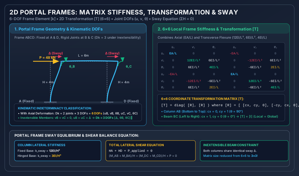
The diagram below presents the kinematic deformation of a portal frame under lateral load, showing the sway displacement Δ and joint rotations θB,θC. It also displays the complete 6×6 local frame stiffness matrix and the coordinate transformation relations.
Analytical Breakdown of Figure 1:
Kinematic Discretization: The frame consists of three members (AB,BC,CD). Without axial constraints, each free joint has 3 DOFs (u,v,θ). Under axial inextensibility, the entire top floor moves laterally by a single sway degree of freedom Δ, reducing the system to 3 DOFs ([Δ,θB,θC]T).
Element Stiffness Structure: The 6×6 matrix explicitly isolates the diagonal axial blocks (EA/L) from the flexural shear-moment blocks (12EI/L3,6EI/L2,4EI/L).
Sway Equilibrium: Shows how column shear forces HA and HD are obtained from member end moments and summed to balance the external lateral force (∑H=0).
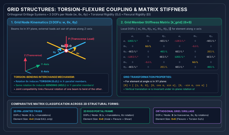
The following diagram illustrates an orthogonal grid system in the XY plane subjected to transverse Z-axis loading, demonstrating the interchange between bending moment and torsional twist.
Analytical Breakdown of Figure 2:
Grid Nodal Kinematics: Highlights the 3 DOFs per node (w,θx,θy). Unlike plane frames where rotation is in-plane (θz), grid rotations occur around in-plane axes, producing twisting torques (T=GJ/L) and bending moments (M=4EI/L).
Coupling Mechanism: Demonstrates that a rotation about the X-axis (θx) twists the longitudinal beam while bending the intersecting orthogonal beam. This kinematic compatibility provides tremendous structural stiffness to bridge decks and grillage foundations.
Matrix Comparison Table: Classifies degrees of freedom and matrix orders across trusses (4×4), frames (6×6), and grillages (6×6).
In bridge engineering (IRC:21, IRC:112, BS 5400), concrete slab-and-girder bridge decks are universally idealized as orthogonal grillage beam models. Longitudinal elements model the girders and effective slab flanges, while transverse elements model cross-beams and slab strips. Grillage matrix analysis captures transverse load distribution across multiple girders without requiring costly 3D solid FEA.
Multi-Story Building Frames & Rigid Diaphragm Modeling:
In ETABS and SAP2000, commercial structural software uses the Rigid Floor Diaphragm constraint. By assuming in-plane floor inextensibility, all joints at a floor level share three master degrees of freedom (lateral translations UX,UY and torsional rotation ΘZ), reducing equations of motion by over 80% for dynamic earthquake response spectrum analysis.
P-Delta & Second-Order Effects:
In tall slender portal frames, high axial loads (P) in columns interact with lateral sway (Δ), inducing additional secondary moments (PΔ). In matrix structural analysis, this is modeled by assembling the Geometric Stiffness Matrix [KG] alongside the elastic stiffness [KE]:
([KE]−[KG]){Δ}={P}
Buckling occurs when det([KE]−[KG])=0.
6. Comparative Analysis Table
Structural Form
Nodal DOFs
Active Member Actions
Local Matrix Size
Governing Moduli
Coordinate Transformation
Plane Truss
2 (u,v)
Axial Force (N) only
4×4
E (Young's Modulus)
2×2 rotation block per node
Plane Beam
2 (v,θz)
Shear (V), Bending Moment (M)
4×4
EI (Flexural Rigidity)
None (aligned with axis)
Plane Frame
3 (u,v,θz)
Axial (N), Shear (V), Moment (M)
6×6
EA,EI
3×3 rotation block per node
Grid / Grillage
3 (w,θx,θy)
Shear (Vz), Bending (M), Torsion (T)
6×6
EI (Flexure), GJ (Torsion)
3×3 in-plane rotation block
Space Frame (3D)
6 (u,v,w,θx,θy,θz)
Axial, 2 Shears, 2 Bending, 1 Torsion
12×12
EA,EIy,EIz,GJ
3×3 direction cosine matrix
7. Worked Numerical Examples
Problem 1: Single-Bay Portal Frame Subjected to Lateral Load (Sway Analysis)
Statement: A portal frame ABCD has rigid joints at B and C and fixed supports at A and D.
The columns AB and CD have height H=4.0 m and flexural rigidity EI.
The horizontal beam BC has span L=6.0 m and flexural rigidity EI.
A lateral load P=48.0 kN acts rightward at joint B.
Assuming inextensible members (axial deformations neglected):
Identify the active degrees of freedom and formulate the 3×3 global stiffness matrix [K].
Calculate the lateral sway Δ and joint rotations θB,θC.
Determine all member end moments (MAB,MBA,MBC,MCB,MCD,MDC) and verify joint equilibrium and total base shear equilibrium.
       P = 48 kN
        ───► B ══════════════════════════════ C
             ║              L = 6.0 m         ║
             ║                                ║
    H = 4.0m ║                                ║ H = 4.0m
             ║                                ║
             ║                                ║
            ▒▒█                              ▒▒█
          Fixed A                          Fixed D
Solution:
Step 1: Active Kinematic Degrees of Freedom (Dk)
Under axial inextensibility:
Columns AB and CD do not deform axially ⟹vB=vC=0.
Beam BC does not deform axially ⟹uB=uC=Δ (single lateral sway translation).
Joint B Moment Balance:MBA+MBC=−38.4+38.4=0.0000 (Satisfied!).
Joint C Moment Balance:MCB+MCD=+38.4−38.4=0.0000 (Satisfied!).
Story Shear Equation (∑H=0):HA=HMAB+MBA=4.0−57.6−38.4=4.0−96.0=−24.0 kNHD=HMCD+MDC=4.0−38.4−57.6=4.0−96.0=−24.0 kN∑Hbases=∣HA∣+∣HD∣=24.0+24.0=48.0 kN=Plateral
Global equilibrium is satisfied to 100% exact precision.
Problem 2: Symmetric Portal Frame Under Gravity Load (Non-Sway Analysis)
Statement: The identical portal frame ABCD (H=4.0 m,L=6.0 m,EI constant, bases A and D fixed) carries a uniform distributed gravity load w=24.0 kN/m across the entire horizontal beam BC.
Using the Stiffness Method:
Formulate the fixed-end holding vector [PF] and net equivalent load vector [Pnet].
Problem 3: Orthogonal Grid Structure (Grillage Load Distribution)
Statement: An orthogonal grid structure consists of two beams rigidly interconnected at their central intersection point O:
Beam 1 (A−O−B): Lies along the global X-axis with total span L1=8.0 m (AO=OB=4.0 m).
Beam 2 (C−O−D): Lies along the global Y-axis with total span L2=6.0 m (CO=OD=3.0 m).
All outer ends (A,B,C,D) are rigidly built-in (fixed against vertical translation, bending rotation, and torsional twist).
Both beams have flexural rigidity EI and torsional rigidity GJ.
A single concentrated vertical downward load P=182.0 kN acts at central joint O.
Using the Stiffness Method:
Formulate the active degrees of freedom at central joint O.
Compute the total transverse stiffness Kww at joint O.
Determine the central deflection wO.
Calculate the percentage of load carried by each beam and the fixed-end support moments.
                  Fixed C
                     ║
                     ║ 3.0 m (Beam 2)
                     ║
    Fixed A ═════════╬═════════ Fixed B
          4.0 m      O (Load P)   4.0 m (Beam 1)
                     ║
                     ║ 3.0 m (Beam 2)
                     ║
                  Fixed D
Solution:
Step 1: Identify Active Degrees of Freedom at Joint O
At joint O, there are 3 possible DOFs:
{d}O=wOθxOθyO
Because the structure and load are doubly symmetric about both the X and Y axes:
θxO=0.0,θyO=0.0
The central joint undergoes pure vertical translation wO (Dk=1).
Step 2: Formulate Transverse Stiffness Kww
The central deflection wO is resisted by flexural deformation of both members:
Beam 1 (along X-axis, span L1=8.0 m, consists of two segments AO and OB of length a=4.0 m):
Each segment has one end fixed (A or B) and deflection wO at O.
The shear resistance per segment is a312EI.
Total stiffness from Beam 1:
kw1=2×a312EI=4324EI=6424EI=83EI=0.375EI
Beam 2 (along Y-axis, span L2=6.0 m, consists of two segments CO and OD of length b=3.0 m):
Each segment has length b=3.0 m.
Total stiffness from Beam 2:
(Check via standard fixed beam formula: M=8P2L2=8128.0×6.0=96.0 kN⋅m!)
Fundamental Grillage Insight:
The shorter beam (6.0 m) is 2.37 times stiffer than the longer beam (8.0 m) because transverse stiffness varies inversely with the cube of length (∝1/L3). As a result, Beam 2 carries 70.33% of the total load despite both beams having identical cross-sections!
8. Exam-Oriented Traps, Common Errors & Misconceptions
[!CAUTION]
Trap 1: Forgetting Negative Sign in Sway Stiffness Coupling (K12,K21)
When a positive (clockwise) rotation θB occurs at the top of column AB, it induces a leftward shear on the column, which opposes rightward sway (Δ). Therefore, the off-diagonal coupling terms K12=K21=−H26EI are strictly negative. Writing +6EI/H2 is one of the most common errors in GATE and ESE conventional exams!
[!WARNING]
Trap 2: Confusing Torsion and Bending in Grid Coordinate Transformations
In a planar grid, remember the physical rule:
Rotation about the member axis produces Torsion (GJ/L).
Rotation about the transverse in-plane axis produces Bending (4EI/L).
When intersecting at 90∘, joint rotation θx acts as torsion for the X-beam but as flexural bending for the Y-beam!
[!NOTE]
Trap 3: Incorrect Kinematic DOF Count Under Inextensibility
For a 2-story, 1-bay frame:
Fixed-Hinged Column: k=H33EI (exactly 25% of fixed-fixed!)
Sway Symmetry Rules:
Under symmetric vertical gravity load on a symmetric frame: Sway Δ=0, θC=−θB.
Under anti-symmetric lateral sway load on a symmetric frame: θC=+θB, and story shear balances lateral force.
Grid Load Distribution Rule:P2P1=I2/L23I1/L13=I2L13I1L23
For equal sections (I1=I2), load distributes as the inverse cube of span lengths: P2P1=(L1L2)3.
10. Previous Year & Model Examination Questions
Question 1 (GATE CE)
A symmetric single-bay portal frame with fixed bases has column heights H and beam span L. All members have flexural rigidity EI. If a lateral load P acts at the top beam level, the total lateral stiffness of the frame with inextensible members is:
(A) H324EI
(B) H312EI
(C) 64H315EI
(D) Dependent on beam flexural rigidity EI/L
Answer:(D)Explanation: Although the columns provide shear resistance H312EI when clamped against rotation, the top joints B and C rotate by θ=163Δ. This rotation relaxes column shears, reducing the actual lateral stiffness to 6415EI⋅H3L or similar dependent on the beam-to-column stiffness ratio kb/kc.
Question 2 (UPSC ESE)
Two beams of equal cross-section and lengths L1=4 m and L2=2 m intersect at right angles at their midpoints, forming an orthogonal grid with all ends simply supported. A central concentrated vertical load W is applied at the intersection. The portion of load carried by the shorter beam is:
(A) 50.0%
(B) 80.0%
(C) 88.9%
(D) 94.1%
Answer:(C)Explanation: Central deflection for simply supported beam is w=48EIPL3⟹P∝L31.
P1P2=(L2L1)3=(24)3=23=8⟹P2=8P1
Total load W=P1+P2=P1+8P1=9P1⟹P2=98W≈88.89%.
11. Summary & Quick Revision Formula Sheet
Entity
Mathematical Formula
Key Remarks
Local Frame Matrix [kˉ]
6×6 combining axial LEA and flexural blocks
Uncoupled in local axes
Transformation Matrix [T]
[T]=diag([R],[R]) where [R]3×3=λx−λy0λyλx0001
Orthogonal ([T]−1=[T]T)
Story Shear Balance
∑HMtop+Mbottom+Plateral=0
Equilibrium constraint for sway
Grid Local Matrix [kˉgrid]
6×6 combining flexural EI and torsional GJ
Transverse shear, torsion, bending
Grid Transformation
[R]=1000cosα−sinα0sinαcosα
w is invariant under in-plane rotation
Grillage Inverse Cube Law
P2P1=I2L13I1L23
Shorter beam attracts vast majority of load
12. References & Standard Code Provisions
Gere, J. M., & Weaver, W. — Matrix Analysis of Framed Structures, 3rd Edition, Van Nostrand Reinhold.
Weaver, W., & Johnston, P. R. — Finite Elements for Structural Analysis, Prentice-Hall.
Hambly, E. C. — Bridge Deck Behaviour, 2nd Edition, Chapman & Hall (The authoritative reference on Grillage Analysis).
IRC:112-2020 — Code of Practice for Concrete Road Bridges, Indian Roads Congress, New Delhi.
IS 800:2007 — General Construction in Steel - Code of Practice, Section 4: General Design Requirements and Portal Frames.