Plastic Collapse Theorems & Independent Collapse Mechanisms
In this chapter (4 topics)
On this page
- 1. Introduction & Conceptual Foundations
- 1.1 The Transition from Indeterminate Structure to Mechanism
- 2. The Three Fundamental Conditions of Plastic Collapse
- 3. The Fundamental Theorems of Plastic Collapse
- 3.1 The Lower Bound (Static / Safe) Theorem
- 3.2 The Upper Bound (Kinematic / Unsafe) Theorem
- 3.3 The Uniqueness Theorem
- 4. Number of Independent Collapse Mechanisms (Nm)
- 4.1 Fundamental Formula
- 4.2 Rules for Identifying Candidate Plastic Hinge Locations (Np)
- 4.3 Classification of Independent Mechanisms
- 5. Mechanism Combination and Hinge Cancellation
- 5.1 The Principle of Hinge Cancellation
- 6. The Principle of Virtual Work in Plastic Mechanics
- 6.1 External Work (WE)
- 6.2 Internal Plastic Work (WI)
- 7. Complete Step-by-Step Procedure: The Kinematic Method
- 8. Worked Numerical Examples
- Problem 1: Fixed Beam with Eccentric Concentrated Load (Uniqueness Verification)
- Problem 2: Single-Bay Portal Frame with Beam, Sway, and Combined Mechanisms
- Problem 3: Two-Span Continuous Beam with Variable Span Capacities
- 9. Common Misconceptions & Exam Pitfalls
- 10. Comparative Summary & Quick Revision Matrix
- 11. Practice Questions & Competitive Examination Problems
- Multiple Choice & Objective Questions
- 12. References & Code Standards
1. Introduction & Conceptual Foundations
1.1 The Transition from Indeterminate Structure to Mechanism
In linear elastic structural analysis, an indeterminate structure with degree of static indeterminacy maintains rigidity as long as its boundary restraints are intact. However, in plastic theory, as external loads are monotonically increased, cross-sections reach their plastic moment capacity () one by one at locations of peak bending moments.
Each fully formed plastic hinge acts as a localized rotational release under constant resisting moment . When a sufficient number of plastic hinges form, the structure transforms into an unstable kinematic linkage with one or more degrees of freedom. This state is known as a Plastic Collapse Mechanism.
   Rigid Indeterminate Structure (D_s redundancies)
      |
      +--> Load increases monotonically
      |
      +--> First plastic hinge forms at max moment section (Redundancy reduces to D_s - 1)
      |
      +--> Successive plastic hinges form with moment redistribution
      |
      +--> Collapse Mechanism forms when N_h = D_s + 1 (Complete Collapse)
           or when a local sub-component forms a mechanism (Partial Collapse)
2. The Three Fundamental Conditions of Plastic Collapse
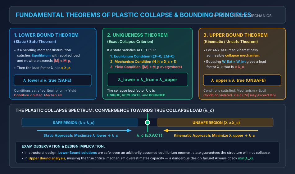
To ascertain whether an assumed collapse load factor () and corresponding bending moment distribution represent the exact physical collapse of a structure, three conditions must be evaluated:
- Equilibrium Condition: The internal bending moments, shears, and axial forces must be in static equilibrium with the factored external collapse loads () across every segment and node of the structure:
- Mechanism Condition: A sufficient number of plastic hinges must form to transform the whole structure, or any isolated part of it, into a kinematic mechanism with at least one degree of freedom (). For complete collapse of a structure with static indeterminacy : (For partial collapse, a localized sub-span may collapse with fewer hinges if that local sub-span satisfies ).
- Yield Condition: At no cross-section along any member may the internal bending moment exceed the plastic moment capacity of that cross-section:
3. The Fundamental Theorems of Plastic Collapse
The interplay among the three conditions gives rise to the three foundational bounding theorems of plastic analysis established by Greenberg, Prager, and Feinberg (1949–1952).
3.1 The Lower Bound (Static / Safe) Theorem
Statement: If a bending moment distribution can be found that satisfies both the Equilibrium Condition with the applied loads and the Yield Condition () everywhere in the structure, then the corresponding load factor is less than or equal to the true collapse load factor :
Engineering & Design Implications
- The static method is inherently SAFE. An engineer who designs a structure based on any statically admissible, equilibrium-satisfying bending moment distribution that does not violate is guaranteed that the actual structure will carry at least that load before collapsing.
- To obtain the exact collapse load via the static method, one must maximize the lower bound:
3.2 The Upper Bound (Kinematic / Unsafe) Theorem
Statement: For any assumed kinematically admissible Mechanism Condition, the load factor calculated by equating the external virtual work to the internal plastic work () is greater than or equal to the true collapse load factor :
Engineering & Design Implications
- The kinematic method is inherently UNSAFE if the wrong mechanism is investigated. If a designer checks several collapse mechanisms but misses the truly critical one, the calculated collapse load will be higher than the actual capacity, leading to catastrophic premature failure.
- To obtain the exact collapse load via the kinematic method, one must search across all possible mechanisms and take the absolute minimum:
3.3 The Uniqueness Theorem
Statement: If a load factor is associated with a bending moment distribution and a displacement field that simultaneously satisfy all three conditions (Equilibrium, Mechanism, and Yield), then that load factor is the unique, exact collapse load factor ():
   +-------------------------------------------------------------+
   |                     UNIQUENESS THEOREM                      |
   |                                                             |
   |   EQUILIBRIUM  +  YIELD       ==> Lower Bound:  lambda <= lambda_c |
   |   EQUILIBRIUM  +  MECHANISM   ==> Upper Bound:  lambda >= lambda_c |
   |   ALL THREE CONDITIONS MET    ==> EXACT COLLAPSE: lambda == lambda_c |
   +-------------------------------------------------------------+
4. Number of Independent Collapse Mechanisms ()
For complex structures such as portal frames, multi-story bents, and continuous beams, infinite arbitrary kinematic combinations can be drawn. To perform systematic analysis, the kinematic space is spanned by a finite set of Independent (Basic) Mechanisms.
4.1 Fundamental Formula
The number of independent collapse mechanisms () is given by:
where:
- (Candidate Plastic Hinge Locations): The total number of cross-sections where plastic hinges can potentially develop.
- (Degree of Static Indeterminacy): The static indeterminacy of the structure under planar loading.
- (Number of Independent Mechanisms): The dimension of the mechanism vector space.
4.2 Rules for Identifying Candidate Plastic Hinge Locations ()
Plastic hinges can only form at cross-sections of peak bending moment or slope discontinuity. In any skeletal framework, includes:
- Rigid Supports & Boundaries: Fixed bases, built-in wall ends (hinge forms at the face of support).
- Points of Concentrated Loads: Sections immediately under point loads or moments.
- Beam-Column Rigid Joints: At any joint connecting two or more members where cross-sectional orientation or stiffness changes.
- Member Discontinuities: Sections where the cross-section changes abruptly (steps, transitions from to ).
- Sections of Maximum Span Moment: Under distributed loads (UDL), the hinge forms at the section of zero shear ().
(Note: Real mechanical frictionless pins and roller supports are already free hinges; they cannot sustain bending moments and therefore do NOT count as plastic hinge locations).
4.3 Classification of Independent Mechanisms
In skeletal frames, independent mechanisms fall into three fundamental geometric categories:
- Beam Mechanisms (): Localized collapse of a single beam span under vertical gravity loads without lateral translation of joints.
- Sway (Panel) Mechanisms (): Lateral drift of columns of a building story under lateral shear.
- Joint Mechanisms (): Pure rotational mechanism at a rigid joint connecting 3 or more members, where plastic hinges form at the member ends framing into the joint.
- Gable Mechanisms (): Spreading of pitched roof rafters in gable portal frames.
5. Mechanism Combination and Hinge Cancellation
Any kinematically admissible collapse mechanism can be expressed as a linear combination of the independent mechanisms:
5.1 The Principle of Hinge Cancellation
When a beam mechanism (which rotates joint clockwise by ) is added to a sway mechanism (which rotates joint counter-clockwise by ), the relative rotation across the joint vanishes:
- Because the relative hinge rotation becomes zero, the plastic hinge at joint disappears (cancels out)!
- Effect on Internal Work (): Cancelling a plastic hinge eliminates a term from the internal energy dissipation, thereby significantly decreasing .
- Effect on External Work (): The external work terms from both lateral and gravity loads add together:
- Result: Because increases while decreases, the combined collapse load factor drops substantially: Hence, combined mechanisms almost invariably govern the collapse of multi-member frames!
6. The Principle of Virtual Work in Plastic Mechanics
The kinematic method computes the collapse load factor through the Principle of Virtual Work applied to the collapse displacement field:
6.1 External Work ()
The external virtual work done by all active external loads as the mechanism undergoes an infinitesimal kinematic virtual displacement :
where is the displacement component of load along its line of action.
6.2 Internal Plastic Work ()
Because all elastic deformations are negligible compared to mechanism rotations at collapse, all internal energy dissipation is confined strictly to the plastic hinges:
where:
- is the plastic moment capacity at hinge .
- is the absolute magnitude of the relative plastic hinge rotation.
- CRITICAL SIGN RULE: Internal plastic energy dissipation is always strictly positive (). Plastic work represents irreversible thermodynamic energy dissipation into plastic slip; a plastic hinge always resists rotation regardless of the sense of rotation.
7. Complete Step-by-Step Procedure: The Kinematic Method
To determine the true collapse load factor of any structure:
- Determine Degree of Indeterminacy (): Count support reactions and closed loops.
- Locate Candidate Plastic Hinges (): Identify all load points, supports, and joint intersections.
- Calculate Independent Mechanisms: .
- Analyze Individual Independent Mechanisms:
- Draw the kinematically admissible deflected shape in terms of a virtual rotation parameter .
- Express all load point deflections () and hinge rotations () in terms of .
- Set to find .
- Formulate Combined Mechanisms: Combine independent modes to cancel common hinges, compute .
- Select Minimum Collapse Load Factor:
- Perform Statics / Lower Bound Check: Construct the corresponding bending moment diagram at . Verify that at all unyielded joints. If verified, the Uniqueness Theorem guarantees that is exact!
8. Worked Numerical Examples
Problem 1: Fixed Beam with Eccentric Concentrated Load (Uniqueness Verification)
Statement: A built-in fixed beam AB of span has a uniform plastic moment capacity . A concentrated vertical load is applied at point C, located at a distance from left support A and from right support B.
- Determine the static indeterminacy , candidate hinge locations , and independent mechanisms .
- Using the Kinematic Method (Upper Bound), compute the collapse load .
- Using the Static Method (Lower Bound), verify the collapse load.
- Confirm uniqueness.
       |<- a = 3 m ->|<--- b = 5 m --->|
      A              C                 B
      [=============[W]===============]
      /|/|/                           /|/|/
      Fixed                           Fixed
Solution:
Step 1: Degrees of Freedom and Hinges
- Fixed beam: (vertical reactions and moments ; ).
- Possible plastic hinge locations ():
- Left fixed end A ()
- Under concentrated load C ()
- Right fixed end B () .
- Number of independent mechanisms: (A single beam mechanism governs complete collapse).
Step 2: Kinematic Method (Upper Bound)
- Let the vertical downward displacement under load C be .
- Segment AC rotates by :
- Segment CB rotates by :
- Hinge rotations at the 3 plastic hinges:
- At fixed support A:
- At load point C:
- At fixed support B:
- External Virtual Work:
- Internal Plastic Work: Substitute and :
- Equating :
- Substituting numerical values ():
Step 3: Static Method (Lower Bound Check)
- Consider the bending moment diagram as the superposition of the "free" simply supported moment () and the "fixing" moment diagram ():
- Free moment under load C:
- At plastic collapse, hogging hinges form at ends A and B:
- The fixing moment along the beam is uniform: .
- The net sagging moment under load C is:
- Yield condition verification:
- At : (Yield met)
- At : (Yield met)
- At : (Yield met)
- For all other points : (Strictly satisfied).
- Because satisfies Equilibrium, Mechanism (), and Yield (), the collapse load is strictly unique:
Problem 2: Single-Bay Portal Frame with Beam, Sway, and Combined Mechanisms
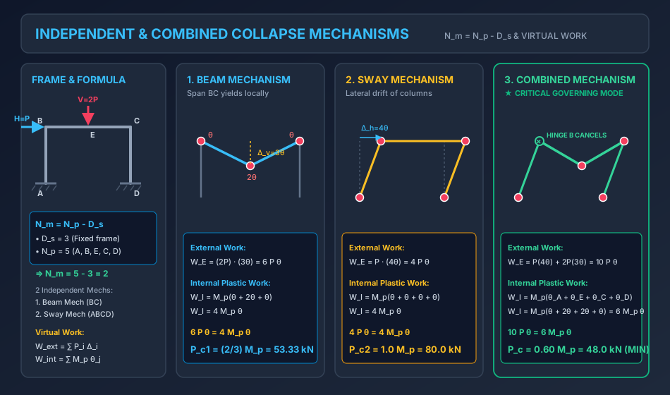
Statement: A rectangular portal frame ABCD has fixed bases at A and D. Column height , beam span . Plastic moment capacity is uniform throughout. The frame carries a horizontal lateral load at joint B (to the right) and a vertical concentrated load at the center of beam BC (point E).
- Determine , and the number of independent mechanisms .
- Analyze the Beam Mechanism.
- Analyze the Sway Mechanism.
- Analyze the Combined Mechanism.
- Identify the true governing collapse load and perform a complete Lower Bound moment check at unyielded joint B.
            V = 2P
              |
              v
       B------+------C
   H=P |      E      |
  ---> |             | h = 4 m
       |             |
       A             D
     /|/|/         /|/|/
       <--- L = 6 m ->
Solution:
Step 1: Structural Determinacy and Mechanism Space
- Fixed bases at A and D reaction components.
- Equations of static equilibrium .
- Static indeterminacy:
- Possible plastic hinge locations ():
- Base A (rigid support)
- Joint B (top of column AB / left end of beam BC)
- Point E (mid-span of beam BC under vertical load )
- Joint C (right end of beam BC / top of column CD)
- Base D (rigid support)
- Number of independent mechanisms: The 2 independent mechanisms are the Beam Mechanism and the Sway Mechanism.
Step 2: Mechanism 1 — Beam Mechanism
- Hinges form at ends and center of beam BC: hinges at B, E, and C.
- Let mid-span vertical deflection be .
- Rotations at hinges:
- Columns AB and CD do not deform laterally .
- Work Equation:
- For :
Step 3: Mechanism 2 — Sway Mechanism
- Hinges form at column bases and tops: hinges at A, B, C, and D.
- Lateral drift .
- Beam BC undergoes rigid body translation .
- Rotations at the 4 column hinges:
- Work Equation:
- For :
Step 4: Mechanism 3 — Combined Mechanism (Beam + Sway)
- Superimpose Sway and Beam mechanisms:
- Sway causes column top B to rotate clockwise by .
- Beam mechanism causes left end of beam B to rotate counter-clockwise by .
- Net relative hinge rotation at joint B: The plastic hinge at Joint B is CANCELLED!
- Hinge rotations in the combined mechanism:
- Base A:
- Mid-span E:
- Joint C:
- Base D:
- External Work:
- Internal Plastic Work:
- Equating :
- For :
Step 5: Selection of True Collapse Load and Lower Bound Proof Comparing the upper bounds:
The Combined Mechanism governs with collapse load .
Static Verification at Unyielded Joint B:
- At column CD: Hinges formed at () and (). Horizontal shear in column CD:
- Horizontal equilibrium of entire frame:
- Column AB equilibrium: Hinge formed at base A ().
- Check Yield Condition: The moment at joint B is of , strictly below yield!
- Since all 3 conditions (Equilibrium, Mechanism, Yield) are fully satisfied, is the exact, mathematically proven collapse load.
Problem 3: Two-Span Continuous Beam with Variable Span Capacities
Statement: A continuous beam ABC rests on a simple pin support at A, an interior roller support at B, and is clamped (fixed) at C.
- Span AB has length and plastic moment capacity .
- Span BC has length and plastic moment capacity .
- Span AB carries a concentrated load at its mid-span.
- Span BC carries a concentrated load at its mid-span. Determine the collapse load and identify which span collapses first.
               W                     1.5W
               |                       |
               v                       v
      A--------+--------B--------------+--------------C
      ^     (3m)  (3m)  ^            (2m)    (2m)    /|/|/
     Pin              Roller                         Fixed
      <--- L1 = 6 m ---><------- L2 = 4 m ----------->
        Mp1 = 100 kNm             Mp2 = 60 kNm
Solution:
Step 1: Redundancy & Possible Plastic Hinges
- Reactions: reactions.
- Equations of equilibrium (vertical force and moment).
- Static indeterminacy: .
- Possible plastic hinge locations ():
- Under load at mid-span of AB.
- Over interior support B (governed by the weaker span capacity: ).
- Under load at mid-span of BC.
- At fixed support C ().
- Number of independent mechanisms:
The 2 independent collapse modes are:
- Mechanism 1: Collapse of Span AB.
- Mechanism 2: Collapse of Span BC.
Step 2: Mechanism 1 — Collapse of Span AB
- Hinges form at mid-span of AB and over support B. Support A rotates freely.
- Let vertical displacement under be .
- Hinge rotations:
- At mid-span AB:
- Over support B:
- External Work:
- Internal Plastic Work:
- Work equation:
Step 3: Mechanism 2 — Collapse of Span BC
- Span BC is fixed at C and continuous over B. Collapse requires 3 hinges: at support B, mid-span of BC, and fixed end C.
- Let vertical displacement under be .
- Hinge rotations:
- At support B:
- At mid-span BC:
- At fixed support C:
- External Work:
- Internal Plastic Work:
- Work equation:
Step 4: Governing Collapse Load & Behavior
- Result: Span BC collapses first at .
- Loads on the structure at collapse:
- Load on Span AB:
- Load on Span BC: .
- When , span AB carries only of its collapse capacity (), meaning span AB remains stable while span BC forms a full collapse mechanism!
9. Common Misconceptions & Exam Pitfalls
[!CAUTION]
- Upper Bound Pitfall: In kinematic mechanism analysis, any assumed mechanism gives a load factor . You must find the minimum load factor among all possible mechanisms. Calling the largest calculated load the collapse load is a severe failure!
- Neglecting Hinge Cancellation: When adding independent mechanisms, students often forget that rotations of opposite signs at a joint cancel each other out. If a joint hinge cancels, it must not be included in the internal work . Keeping it overestimates and yields an incorrect (artificially high) collapse load.
- Frictionless Pins Do Not Form Plastic Hinges: A real mechanical pin support (like a simple end support) has zero moment capacity (). It rotates freely without any plastic dissipation. Never include at a pinned or roller end support!
- Governing Moment at Section Discontinuities: Over an intermediate support where two spans with different capacities and meet, the plastic hinge forms in the weaker member, so the capacity is strictly .
- Negative Plastic Work is Impossible: Plastic hinge work is always positive: . Never write even if the rotation is clockwise or opposite in sign.
10. Comparative Summary & Quick Revision Matrix
| Parameter / Feature | Lower Bound (Static) Theorem | Upper Bound (Kinematic) Theorem | Uniqueness Theorem |
|---|---|---|---|
| Primary Variable | Bending moment distribution | Collapse displacement mechanism | Simultaneous and mechanism |
| Conditions Satisfied | Equilibrium + Yield () | Equilibrium + Mechanism () | Equilibrium + Yield + Mechanism |
| Relation to True Load | (Safe) | (Unsafe) | (Exact) |
| Optimization Goal | Maximize lower bound: | Minimize upper bound: | Intersection point () |
| Independent Modes | Redundant force selection | Independent mechanisms: | Full consistency check |
| Typical Structural Use | Foundation slabs, grid design | Portal frames, continuous beams | Research benchmarks & code verification |
11. Practice Questions & Competitive Examination Problems
Multiple Choice & Objective Questions
-
[GATE CE] A propped cantilever beam of span carries a concentrated load at mid-span. The plastic moment capacity is . The collapse load is:
- (A)
- (B)
- (C)
- (D)
Answer: (B) .
-
[ESE CE] For a single-story, two-bay rigid portal frame with fixed column bases, the degree of static indeterminacy under general in-plane loading is:
- (A) 3
- (B) 6
- (C) 5
- (D) 4
Answer: (B) 2 closed loops or 3 fixed bases (). .
-
[SSC JE] The number of independent plastic collapse mechanisms for a structure with 7 possible plastic hinge locations and static indeterminacy of 4 is:
- (A) 11
- (B) 3
- (C) 28
- (D) 4
Answer: (B) .
-
[State AE] The Uniqueness Theorem in plastic collapse analysis states that:
- (A) The collapse load is always greater than the yield load
- (B) The collapse load is unique if equilibrium, mechanism, and yield conditions are all satisfied
- (C) Every indeterminate structure has only one independent mechanism
- (D) The plastic moment is independent of material yield stress
Answer: (B) Simultaneous satisfaction of Equilibrium, Mechanism, and Yield conditions yields the unique exact collapse load.
12. References & Code Standards
- IS 800:2007: General Construction in Steel — Code of Practice, Section 12 (Plastic Design), Bureau of Indian Standards.
- AISC 360-16: Specification for Structural Steel Buildings, Appendix 1 (Design by Inelastic Analysis).
- Eurocode 3 (EN 1993-1-1): Design of Steel Structures — Part 1-1: General Rules and Rules for Buildings.
- Baker, J. F., & Heyman, J. (1969). Plastic Design of Frames: Volume 1, Fundamentals. Cambridge University Press.
- Horne, M. R. (1979). Plastic Theory of Structures. Pergamon Press.
- Neal, B. G. (1977). The Plastic Methods of Structural Analysis. Chapman and Hall.