SA-03-03 Chapter 03 · Classical Indeterminate Structures

Slope-Deflection Method for Beams and Rigid Frames

Prerequisites
Static Indeterminacy of Beams, Trusses & Rigid Frames (2D & 3D) SA-01-01 , Kinematic Indeterminacy & Degrees of Freedom SA-01-02 , Propped Cantilevers & Fixed Beams: Classical Indeterminate Formulations SA-03-01 , Clapeyron's Three-Moment Equation for Continuous Beams SA-03-02
Keywords
slope-deflection method · displacement method · fixed-end moments · joint rotations · portal frame sway · shear equation
In this chapter (4 topics)
On this page

1. Introduction & Displacement Method Philosophy

The Slope-Deflection Method, introduced by American structural engineer George A. Maney in 1915, marks the historical transition from Force Methods (Flexibility Methods) to Displacement Methods (Stiffness Methods).

In classical force methods (such as the Method of Consistent Deformations, Castigliano's Theorem of Least Work, or Clapeyron's Three-Moment Theorem), the primary unknowns are redundant internal forces or support reactions (DsD_s). In contrast, the Slope-Deflection Method treats the joint displacements—rotations (θ\theta) and translations (Δ\Delta)—as the primary unknowns (DkD_k).

Classical Structural Analysis Framework:
┌───────────────────────────────────────┬───────────────────────────────────────┐
│     FORCE / FLEXIBILITY METHODS       │    DISPLACEMENT / STIFFNESS METHODS   │
├───────────────────────────────────────┼───────────────────────────────────────┤
│ • Primary Unknowns: Forces (R, M)     │ • Primary Unknowns: Displacements (θ, Δ)│
│ • Governing Basis: Static Indet. (D_s)│ • Governing Basis: Kinematic Indet. (D_k)│
│ • Equations: Compatibility of Strain  │ • Equations: Joint & Shear Equilibrium │
│ • Examples: Virtual Work, Castigliano,│ • Examples: Slope-Deflection, Moment  │
│   Three-Moment Equation               │   Distribution, Matrix Stiffness (FEA)│
└───────────────────────────────────────┴───────────────────────────────────────┘

1.1 Why Displacement Methods Dominate Modern Computational Engineering

  1. Algorithmic Uniformity: The relation between end moments and joint displacements for any member depends purely on member geometry (L,I,EL, I, E) and boundary displacements, completely decoupled from the rest of the structure.
  2. Computational Superiority when Dk<DsD_k < D_s: In heavily indeterminate civil structures (e.g., multi-story multi-bay continuous frames), the degree of static indeterminacy DsD_s can be in the hundreds, whereas kinematic unknowns DkD_k (especially when axial deformation is neglected) are significantly fewer.
  3. The Foundation of FEA: The Slope-Deflection equations form the exact analytical basis for the member stiffness matrix [k][k] utilized in modern structural analysis software (STAAD.Pro, SAP2000, ETABS, ANSYS).

2. Mathematical Formulation & First-Principles Derivation

2.1 Standard Sign Convention

A consistent sign convention is vital in the Slope-Deflection Method:

  • Joint Rotations (θ\theta): A rotation of a joint in the clockwise direction is taken as POSITIVE (+).
  • Member End Moments (MM): An internal bending moment acting on a member end in the clockwise direction is taken as POSITIVE (+).
  • Chord Rotation / Lateral Drift (ψ=ΔL\psi = \frac{\Delta}{L}): The angle of rotation of the member axis (chord) connecting the two displaced joint ends. If the chord rotates clockwise, ψ\psi is taken as POSITIVE (+).
Clockwise Rotations and Moments are POSITIVE:

      + θ_A (CW)                                   + θ_B (CW)
        ╭─╮                                          ╭─╮
        │ ↻ │                                        │ ↻ │
        ╰─╯                                          ╰─╯
     A ─────────────────────────────────────────────── B
     (↻) + M_AB (CW)                           (↻) + M_BA (CW)

2.2 Derivation of the Fundamental Slope-Deflection Equations

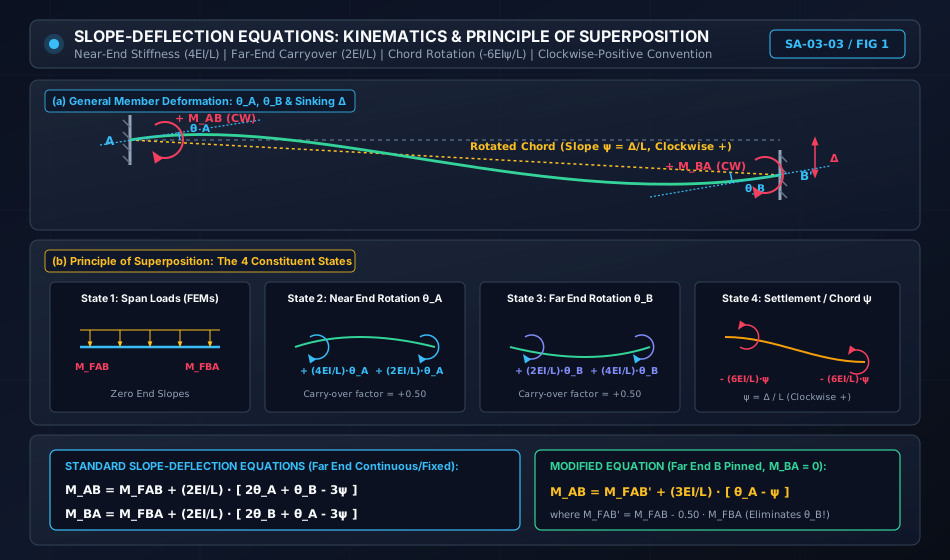
Consider a prismatic member ABAB of length LL and flexural rigidity EIEI. Under the combined action of external transverse loads and arbitrary end displacements (θA,θB,Δ\theta_A, \theta_B, \Delta), the total end moment is evaluated by the Principle of Superposition of four constituent structural states:

Total Moment M_AB = (State 1: FEM) + (State 2: θ_A) + (State 3: θ_B) + (State 4: Δ)

State 1: Member Clamped at Both Ends Under Span Loads

With joint rotations and translations locked (θA=0,θB=0,Δ=0\theta_A = 0, \theta_B = 0, \Delta = 0), the applied span loads produce Fixed-End Moments (FEMs):

MAB(1)=MFAB,MBA(1)=MFBAM_{AB}^{(1)} = M_{FAB}, \qquad M_{BA}^{(1)} = M_{FBA}

State 2: Near-End Rotation θA\theta_A (Far End BB Clamped)

Subjecting end AA to a clockwise rotation θA\theta_A while keeping end BB completely fixed (θB=0,Δ=0\theta_B = 0, \Delta = 0):

  • Moment required to produce rotation θA\theta_A at near end AA (Flexural Stiffness): MAB(2)=4EILθAM_{AB}^{(2)} = \frac{4EI}{L} \theta_A
  • Carry-over moment induced at the far clamped end BB (Carry-Over Factor =+0.50= +0.50): MBA(2)=2EILθAM_{BA}^{(2)} = \frac{2EI}{L} \theta_A

State 3: Far-End Rotation θB\theta_B (Near End AA Clamped)

Subjecting end BB to a clockwise rotation θB\theta_B while keeping end AA completely fixed (θA=0,Δ=0\theta_A = 0, \Delta = 0):

  • Carry-over moment induced at near end AA: MAB(3)=2EILθBM_{AB}^{(3)} = \frac{2EI}{L} \theta_B
  • Moment required to produce rotation θB\theta_B at end BB: MBA(3)=4EILθBM_{BA}^{(3)} = \frac{4EI}{L} \theta_B

State 4: Relative Lateral Displacement Δ\Delta (Chord Rotation ψ\psi)

Displacing end BB transversely relative to end AA by an amount Δ\Delta without allowing any joint rotation (θA=0,θB=0\theta_A = 0, \theta_B = 0):

  • The member chord rotates through an angle ψ=ΔL\psi = \frac{\Delta}{L} (clockwise).
  • To maintain zero slope at both ends, counter-clockwise (negative) restoring couples must act at both ends: MAB(4)=−6EIΔL2=−6EILψM_{AB}^{(4)} = - \frac{6EI\Delta}{L^2} = - \frac{6EI}{L} \psi MBA(4)=−6EIΔL2=−6EILψM_{BA}^{(4)} = - \frac{6EI\Delta}{L^2} = - \frac{6EI}{L} \psi

The Canonical Slope-Deflection Equations

Summing all four states algebraically:

MAB=MFAB+4EILθA+2EILθB−6EILψM_{AB} = M_{FAB} + \frac{4EI}{L} \theta_A + \frac{2EI}{L} \theta_B - \frac{6EI}{L} \psi MBA=MFBA+2EILθA+4EILθB−6EILψM_{BA} = M_{FBA} + \frac{2EI}{L} \theta_A + \frac{4EI}{L} \theta_B - \frac{6EI}{L} \psi

Factoring out 2EIL\frac{2EI}{L}:

MAB=MFAB+2EIL(2θA+θB−3ψ)\boxed{ M_{AB} = M_{FAB} + \frac{2EI}{L} \left( 2\theta_A + \theta_B - 3\psi \right) } MBA=MFBA+2EIL(2θB+θA−3ψ)\boxed{ M_{BA} = M_{FBA} + \frac{2EI}{L} \left( 2\theta_B + \theta_A - 3\psi \right) }

3. Standard Fixed-End Moments (FEMs) Reference Table

All formulas adhere strictly to the Clockwise-Positive sign convention (anticlockwise FEM at left is negative; clockwise FEM at right is positive):

Load Configuration on Span LL Near-End FEM (MFABM_{FAB}) Far-End FEM (MFBAM_{FBA})
Uniformly Distributed Load (ww) −wL212-\frac{w L^2}{12} +wL212+\frac{w L^2}{12}
Central Concentrated Load (PP at L/2L/2) −PL8-\frac{P L}{8} +PL8+\frac{P L}{8}
Eccentric Concentrated Load (PP at a,ba, b) −Pab2L2-\frac{P a b^2}{L^2} +Pa2bL2+\frac{P a^2 b}{L^2}
Symmetrical Triangular Load (Peak w0w_0 at midspan) −5w0L296-\frac{5 w_0 L^2}{96} +5w0L296+\frac{5 w_0 L^2}{96}
Linearly Increasing Triangular Load (00 to w0w_0) −w0L230-\frac{w_0 L^2}{30} +w0L220+\frac{w_0 L^2}{20}
Concentrated Couple (M0M_0 at distance aa from left) +M0b(2a−b)L2+\frac{M_0 b (2a - b)}{L^2} +M0a(2b−a)L2+\frac{M_0 a (2b - a)}{L^2}
Support Settlement (Δ\Delta, end BB sinks) −6EIΔL2-\frac{6EI\Delta}{L^2} −6EIΔL2-\frac{6EI\Delta}{L^2}

4. Modified Slope-Deflection Equation for a Hinged / Pinned Far End

When an exterior end of a continuous beam or frame (say, far end BB) rests on a frictionless pin or roller support, the internal bending moment at that end must be zero:

MBA=0M_{BA} = 0

Rather than carrying θB\theta_B as an independent unknown throughout the simultaneous equations, we can express θB\theta_B in terms of θA\theta_A and ψ\psi:

0=MFBA+2EIL(2θB+θA−3ψ)0 = M_{FBA} + \frac{2EI}{L} \left( 2\theta_B + \theta_A - 3\psi \right)   ⟹  2θB=−θA+3ψ−L2EIMFBA\implies 2\theta_B = - \theta_A + 3\psi - \frac{L}{2EI} M_{FBA}

Substitute this expression for 2θB2\theta_B into the equation for near-end moment MABM_{AB}:

MAB=MFAB+2EIL[2θA+(−12θA+32ψ−L4EIMFBA)−3ψ]M_{AB} = M_{FAB} + \frac{2EI}{L} \left[ 2\theta_A + \left( -\frac{1}{2}\theta_A + \frac{3}{2}\psi - \frac{L}{4EI} M_{FBA} \right) - 3\psi \right] MAB=MFAB−12MFBA+2EIL(32θA−32ψ)M_{AB} = M_{FAB} - \frac{1}{2} M_{FBA} + \frac{2EI}{L} \left( \frac{3}{2}\theta_A - \frac{3}{2}\psi \right) MAB=MFAB′+3EIL(θA−ψ)\boxed{ M_{AB} = M_{FAB}' + \frac{3EI}{L} \left( \theta_A - \psi \right) }

where:

MFAB′=MFAB−12MFBAM_{FAB}' = M_{FAB} - \frac{1}{2} M_{FBA}

and MBA≡0M_{BA} \equiv 0.

[!TIP] Computational Efficiency: Using the modified slope-deflection equation reduces the stiffness from 4EIL\frac{4EI}{L} to 3EIL\frac{3EI}{L} (a 25%25\% reduction reflecting the loss of rotational restraint at the pinned end), automatically eliminating θB\theta_B from the system of equations!


5. Engineering Diagrams & Visual Explanations

5.1 Member Kinematics & Superposition Breakdown

The graphic below illustrates the general deformed configuration of an indeterminate flexural element and breaks down the four constituent superposition states.

Slope-Deflection Derivation Kinematics

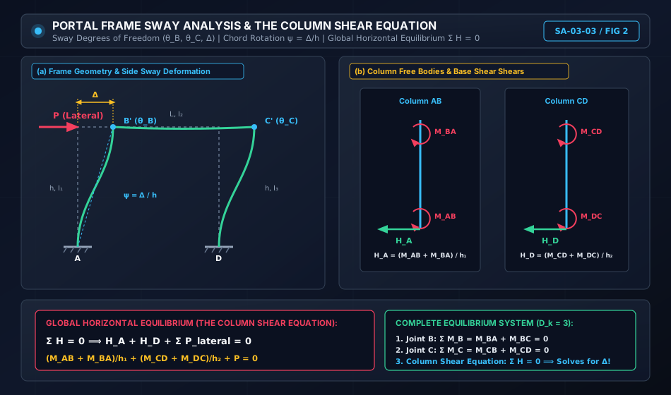
5.2 Portal Frame Sway & The Column Shear Equation

When portal frames are subjected to lateral loads or asymmetric conditions, joint translations (Δ\Delta) occur. The graphic below illustrates frame sway kinematics, column free bodies, and the derivation of the global shear equation.

Portal Frame Sway and Shear Equation

6. Joint Equilibrium & Side Sway Analysis in Rigid Frames

6.1 Joint Moment Equilibrium Equations

In any continuous beam or rigid frame, every monolithic joint must maintain rotational equilibrium:

∑Mjoint=0\sum M_{\text{joint}} = 0

For example, at an interior joint BB connecting members BABA and BCBC:

MBA+MBC=0M_{BA} + M_{BC} = 0

For a rigid frame joint BB connecting column BABA and beam BCBC:

MBA+MBC=0M_{BA} + M_{BC} = 0

If an external concentrated moment MextM_{\text{ext}} acts directly at joint BB (clockwise):

MBA+MBC=MextM_{BA} + M_{BC} = M_{\text{ext}}

6.2 Side Sway in Rigid Portal Frames

Side sway is the lateral translation of the horizontal girder of a frame relative to its base.

Conditions Under Which Sway Occurs:

  1. Asymmetric Loading: Even if the frame geometry is symmetric, asymmetric vertical loads induce sway.
  2. Asymmetric Geometry: Unequal column heights (h1≠h2h_1 \ne h_2).
  3. Asymmetric Stiffness: Unequal column cross-sections (I1≠I2I_1 \ne I_2).
  4. Lateral Loading: Any horizontal wind, seismic, or blast force acting on the columns or roof beam.
  5. Differential Settlement: Unequal vertical settlement of column foundations.

Conditions for Non-Sway Frames:

A frame will NOT sway if and only if:

  1. The geometry is completely symmetric (h1=h2,I1=I2h_1 = h_2, I_1 = I_2).
  2. The applied loads are completely symmetric about the centerline.
  3. The column base supports are identical (both fixed or both hinged).
  4. Or, the frame is laterally restrained by physical bracing or shear walls.

6.3 The Column Shear Equation (Global Horizontal Equilibrium)

When a frame sways laterally by Δ\Delta, chord rotations develop in the columns:

ψAB=Δh1,ψCD=Δh2\psi_{AB} = \frac{\Delta}{h_1}, \qquad \psi_{CD} = \frac{\Delta}{h_2}

Because axial deformations in the roof girder BCBC are negligible, both columns sway by the exact same horizontal displacement Δ\Delta.

This introduces an additional unknown (Δ\Delta), requiring an additional governing equation beyond joint moment equilibrium. This equation is the Column Shear Equation:

Isolate each column as a free body:

  • For column ABAB (height h1h_1): Taking moments about top joint BB: HA⋅h1−MAB−MBA+Mload, AB=0  ⟹  HA=MAB+MBA−Mload, ABh1H_A \cdot h_1 - M_{AB} - M_{BA} + M_{\text{load, } AB} = 0 \implies H_A = \frac{M_{AB} + M_{BA} - M_{\text{load, } AB}}{h_1}
  • For column CDCD (height h2h_2): Taking moments about top joint CC: HD⋅h2−MDC−MCD+Mload, CD=0  ⟹  HD=MCD+MDC−Mload, CDh2H_D \cdot h_2 - M_{DC} - M_{CD} + M_{\text{load, } CD} = 0 \implies H_D = \frac{M_{CD} + M_{DC} - M_{\text{load, } CD}}{h_2}

Considering global horizontal equilibrium of the entire portal frame (∑H=0\sum H = 0):

HA+HD+∑Phorizontal=0\boxed{ H_A + H_D + \sum P_{\text{horizontal}} = 0 }

Substituting HAH_A and HDH_D in terms of the Slope-Deflection equations yields the third governing equation required to solve for Δ\Delta.


7. Solved Numerical Examples

Example 1: Continuous Beam with Pinned Far End (Modified Equation)

Problem Statement:
Analyze the two-span continuous beam ABCABC shown below using the Slope-Deflection Method:

  • Support AA is clamped (fixed) (θA=0\theta_A = 0).
  • Support BB is a continuous simple roller support.
  • Support CC is a pinned end (MCB=0M_{CB} = 0).
  • Span AB=L1=6.0 mAB = L_1 = 6.0\text{ m}, flexural rigidity (EI)1=2EI(EI)_1 = 2EI. Load: Uniformly distributed load w=24.0 kN/mw = 24.0\text{ kN/m}.
  • Span BC=L2=4.0 mBC = L_2 = 4.0\text{ m}, flexural rigidity (EI)2=EI(EI)_2 = EI. Load: Central concentrated point load P=40.0 kNP = 40.0\text{ kN}.
  • No support settlement occurs (ψ=0\psi = 0).

Determine:

  1. Joint rotation θB\theta_B.
  2. Final member end moments MAB,MBA,MBC,MCBM_{AB}, M_{BA}, M_{BC}, M_{CB}.
  3. Vertical support reactions RA,RB,RCR_A, R_B, R_C.
  4. Maximum span moment in span ABAB.
   Fixed                 24 kN/m                         40 kN
  ┌──┐          ┌───────────────────────┐                  ↓
  │  │          ▼ ▼ ▼ ▼ ▼ ▼ ▼ ▼ ▼ ▼ ▼ ▼ │           2 m    │    2 m
  │  │[▲]──────────────────────────────[▲]─────────────────┴───────────────[▲]
  └──┘ A         L₁ = 6 m, 2EI          B              L₂ = 4 m, EI         C (Hinged)

Solution:

Step 1: Kinematic Unknowns (DkD_k)

  • At fixed end AA: θA=0\theta_A = 0.
  • At support BB: θB\theta_B is unknown.
  • At pinned end CC: MCB=0M_{CB} = 0. By using the modified slope-deflection equation, θC\theta_C is eliminated.
  • Total active kinematic degree of freedom: Dk=1D_k = 1 (θB\theta_B).

Step 2: Calculate Fixed-End Moments (FEMs)

  • Span ABAB (L1=6 m,w=24 kN/mL_1 = 6\text{ m}, w = 24\text{ kN/m}):

    MFAB=−wL1212=−24×6212=−72.0 kN⋅mM_{FAB} = - \frac{w L_1^2}{12} = - \frac{24 \times 6^2}{12} = -72.0\text{ kN}\cdot\text{m} MFBA=+wL1212=+24×6212=+72.0 kN⋅mM_{FBA} = + \frac{w L_1^2}{12} = + \frac{24 \times 6^2}{12} = +72.0\text{ kN}\cdot\text{m}
  • Span BCBC (L2=4 m,P=40 kNL_2 = 4\text{ m}, P = 40\text{ kN} at midspan):

    MFBC=−PL28=−40×48=−20.0 kN⋅mM_{FBC} = - \frac{P L_2}{8} = - \frac{40 \times 4}{8} = -20.0\text{ kN}\cdot\text{m} MFCB=+PL28=+40×48=+20.0 kN⋅mM_{FCB} = + \frac{P L_2}{8} = + \frac{40 \times 4}{8} = +20.0\text{ kN}\cdot\text{m}
  • Modified FEM for span BCBC with pinned far end CC:

    MFBC′=MFBC−12MFCB=−20.0−12(+20.0)=−30.0 kN⋅mM_{FBC}' = M_{FBC} - \frac{1}{2} M_{FCB} = -20.0 - \frac{1}{2}(+20.0) = -30.0\text{ kN}\cdot\text{m}

Step 3: Formulate Slope-Deflection Equations

  • Span ABAB (Standard equation, θA=0,ψ=0\theta_A = 0, \psi = 0):

    MAB=MFAB+2(2EI)6(2θA+θB)=−72.0+23EIθBM_{AB} = M_{FAB} + \frac{2(2EI)}{6} (2\theta_A + \theta_B) = -72.0 + \frac{2}{3} EI \theta_B MBA=MFBA+2(2EI)6(2θB+θA)=+72.0+43EI(2θB)=+72.0+83EIθBM_{BA} = M_{FBA} + \frac{2(2EI)}{6} (2\theta_B + \theta_A) = +72.0 + \frac{4}{3} EI (2\theta_B) = +72.0 + \frac{8}{3} EI \theta_B
  • Span BCBC (Modified equation for hinged far end CC, ψ=0\psi = 0):

    MBC=MFBC′+3EI4θB=−30.0+34EIθBM_{BC} = M_{FBC}' + \frac{3EI}{4} \theta_B = -30.0 + \frac{3}{4} EI \theta_B MCB≡0M_{CB} \equiv 0

Step 4: Joint Equilibrium at BB

∑MB=0  ⟹  MBA+MBC=0\sum M_B = 0 \implies M_{BA} + M_{BC} = 0 (+72.0+83EIθB)+(−30.0+34EIθB)=0\left( +72.0 + \frac{8}{3} EI \theta_B \right) + \left( -30.0 + \frac{3}{4} EI \theta_B \right) = 0 42.0+(32+912)EIθB=0  ⟹  42.0+4112EIθB=042.0 + \left( \frac{32 + 9}{12} \right) EI \theta_B = 0 \implies 42.0 + \frac{41}{12} EI \theta_B = 0 EIθB=−42.0×1241=−504.041≈−12.2927 kN⋅m2EI \theta_B = - \frac{42.0 \times 12}{41} = - \frac{504.0}{41} \approx \mathbf{-12.2927\text{ kN}\cdot\text{m}^2}

Step 5: Compute Final Member End Moments

MAB=−72.0+23(−12.2927)=−72.0−8.1951=−88.390 kN⋅m(Anticlockwise)M_{AB} = -72.0 + \frac{2}{3}(-12.2927) = -72.0 - 8.1951 = \mathbf{-88.390\text{ kN}\cdot\text{m}} \quad \text{(Anticlockwise)} MBA=+72.0+83(−12.2927)=+72.0−32.7805=+39.220 kN⋅m(Clockwise)M_{BA} = +72.0 + \frac{8}{3}(-12.2927) = +72.0 - 32.7805 = \mathbf{+39.220\text{ kN}\cdot\text{m}} \quad \text{(Clockwise)} MBC=−30.0+34(−12.2927)=−30.0−9.2195=−39.220 kN⋅m(Anticlockwise)M_{BC} = -30.0 + \frac{3}{4}(-12.2927) = -30.0 - 9.2195 = \mathbf{-39.220\text{ kN}\cdot\text{m}} \quad \text{(Anticlockwise)} MCB=0.000 kN⋅mM_{CB} = \mathbf{0.000\text{ kN}\cdot\text{m}}

Joint Equilibrium Check:

MBA+MBC=+39.2195−39.2195=0.000[EXACT BALANCE]M_{BA} + M_{BC} = +39.2195 - 39.2195 = 0.000 \quad \text{[EXACT BALANCE]}

Step 6: Compute Support Reactions

  • Span ABAB (L1=6 mL_1 = 6\text{ m}):
    Taking moments about BB:

    RA×6−24×622+MAB+MBA=0R_A \times 6 - \frac{24 \times 6^2}{2} + M_{AB} + M_{BA} = 0 6RA−432.0+(−88.3902)+(+39.2195)=06 R_A - 432.0 + (-88.3902) + (+39.2195) = 0 6RA=432.0+49.1707=481.1707  ⟹  RA=80.195 kN6 R_A = 432.0 + 49.1707 = 481.1707 \implies \mathbf{R_A = 80.195\text{ kN}} RBA=(24×6)−80.1951=63.805 kNR_{BA} = (24 \times 6) - 80.1951 = \mathbf{63.805\text{ kN}}
  • Span BCBC (L2=4 mL_2 = 4\text{ m}):
    Taking moments about BB:

    RC×4−(40×2)−MBC=0(since MBC is anticlockwise on beam)R_C \times 4 - (40 \times 2) - M_{BC} = 0 \quad (\text{since } M_{BC} \text{ is anticlockwise on beam}) 4RC=80.0−39.2195=40.7805  ⟹  RC=10.195 kN4 R_C = 80.0 - 39.2195 = 40.7805 \implies \mathbf{R_C = 10.195\text{ kN}} RBC=40.0−10.1951=29.805 kNR_{BC} = 40.0 - 10.1951 = \mathbf{29.805\text{ kN}}
  • Total Intermediate Support Reaction RBR_B:

    RB=RBA+RBC=63.8049+29.8049=93.610 kNR_B = R_{BA} + R_{BC} = 63.8049 + 29.8049 = \mathbf{93.610\text{ kN}}

Global Vertical Equilibrium Check:

∑Fy=RA+RB+RC=80.1951+93.6098+10.1951=184.000 kN\sum F_y = R_A + R_B + R_C = 80.1951 + 93.6098 + 10.1951 = 184.000\text{ kN} Total applied load=(24×6)+40=184.0 kN[EXACT MATCH]\text{Total applied load} = (24 \times 6) + 40 = 184.0\text{ kN} \quad \text{[EXACT MATCH]}

Step 7: Maximum Span Sagging Moment in Span ABAB
Shear force in span ABAB: V(x)=RA−24x=0  ⟹  x0=80.195124=3.342 mV(x) = R_A - 24 x = 0 \implies x_0 = \frac{80.1951}{24} = \mathbf{3.342\text{ m}} from AA.

Mmax⁡,AB=MAB+RAx0−24x022=−88.3902+80.1951(3.3415)−12(3.3415)2M_{\max, AB} = M_{AB} + R_A x_0 - \frac{24 x_0^2}{2} = -88.3902 + 80.1951(3.3415) - 12(3.3415)^2 Mmax⁡,AB=−88.3902+267.9691−133.9845=+45.594 kN⋅mM_{\max, AB} = -88.3902 + 267.9691 - 133.9845 = \mathbf{+45.594\text{ kN}\cdot\text{m}}

Example 2: Symmetrical Portal Frame Subjected to Lateral Load (Sway Analysis)

Problem Statement:
Analyze the rectangular portal frame ABCDABCD shown below:

  • Columns ABAB and CDCD have height h=4.0 mh = 4.0\text{ m} and flexural rigidity EIEI.
  • Beam BCBC has span L=6.0 mL = 6.0\text{ m} and flexural rigidity 2EI2EI.
  • Column bases AA and DD are fixed (θA=0,θD=0\theta_A = 0, \theta_D = 0).
  • A lateral horizontal load of P=30.0 kNP = 30.0\text{ kN} acts at joint BB towards the right.
  • No transverse loads act on the members.

Determine:

  1. Joint rotations θB,θC\theta_B, \theta_C and lateral sway displacement Δ\Delta.
  2. Final member end moments.
  3. Base shear forces HAH_A and HDH_D.
     P = 30 kN
     ───► B ─────────────────────────────── C
          │         L = 6 m, 2EI            │
          │                                 │
   h = 4m │ EI                           EI │ h = 4m
          │                                 │
         [▲]                               [▲]
       Fixed A                           Fixed D

Solution:

Step 1: Kinematic Unknowns (DkD_k)
The frame is free to sway laterally by displacement Δ\Delta.

  • Degrees of Freedom: Joint rotations θB,θC\theta_B, \theta_C, and chord rotation ψ=Δ4\psi = \frac{\Delta}{4}.
  • Total kinematic unknowns: Dk=3D_k = 3 (θB,θC,ψ\theta_B, \theta_C, \psi).

Step 2: Fixed-End Moments (FEMs)
Because there are no span loads on AB,BCAB, BC, or CDCD:

MFAB=MFBA=MFBC=MFCB=MFCD=MFDC=0M_{FAB} = M_{FBA} = M_{FBC} = M_{FCB} = M_{FCD} = M_{FDC} = 0

Step 3: Slope-Deflection Equations

  • Column ABAB (θA=0,ψAB=ψ\theta_A = 0, \psi_{AB} = \psi):

    MAB=2EI4(2(0)+θB−3ψ)=0.5EIθB−1.5EIψM_{AB} = \frac{2EI}{4} (2(0) + \theta_B - 3\psi) = 0.5 EI \theta_B - 1.5 EI \psi MBA=2EI4(2θB+0−3ψ)=1.0EIθB−1.5EIψM_{BA} = \frac{2EI}{4} (2\theta_B + 0 - 3\psi) = 1.0 EI \theta_B - 1.5 EI \psi
  • Beam BCBC (EIb=2EI,L=6 mEI_b = 2EI, L = 6\text{ m}, no sway for beam ψBC=0\psi_{BC} = 0):

    MBC=2(2EI)6(2θB+θC)=43EIθB+23EIθCM_{BC} = \frac{2(2EI)}{6} (2\theta_B + \theta_C) = \frac{4}{3} EI \theta_B + \frac{2}{3} EI \theta_C MCB=2(2EI)6(2θC+θB)=43EIθC+23EIθBM_{CB} = \frac{2(2EI)}{6} (2\theta_C + \theta_B) = \frac{4}{3} EI \theta_C + \frac{2}{3} EI \theta_B
  • Column CDCD (θD=0,ψCD=ψ\theta_D = 0, \psi_{CD} = \psi):

    MCD=2EI4(2θC+0−3ψ)=1.0EIθC−1.5EIψM_{CD} = \frac{2EI}{4} (2\theta_C + 0 - 3\psi) = 1.0 EI \theta_C - 1.5 EI \psi MDC=2EI4(2(0)+θC−3ψ)=0.5EIθC−1.5EIψM_{DC} = \frac{2EI}{4} (2(0) + \theta_C - 3\psi) = 0.5 EI \theta_C - 1.5 EI \psi

Step 4: Equilibrium Equations

  1. Joint BB Equilibrium:

    MBA+MBC=0M_{BA} + M_{BC} = 0 (1.0EIθB−1.5EIψ)+(43EIθB+23EIθC)=0\left( 1.0 EI \theta_B - 1.5 EI \psi \right) + \left( \frac{4}{3} EI \theta_B + \frac{2}{3} EI \theta_C \right) = 0 73EIθB+23EIθC−1.5EIψ=0— (Eq. 1)\frac{7}{3} EI \theta_B + \frac{2}{3} EI \theta_C - 1.5 EI \psi = 0 \quad \text{--- (Eq. 1)}
  2. Joint CC Equilibrium:

    MCB+MCD=0M_{CB} + M_{CD} = 0 (23EIθB+43EIθC)+(1.0EIθC−1.5EIψ)=0\left( \frac{2}{3} EI \theta_B + \frac{4}{3} EI \theta_C \right) + \left( 1.0 EI \theta_C - 1.5 EI \psi \right) = 0 23EIθB+73EIθC−1.5EIψ=0— (Eq. 2)\frac{2}{3} EI \theta_B + \frac{7}{3} EI \theta_C - 1.5 EI \psi = 0 \quad \text{--- (Eq. 2)}

    Subtracting Eq. (2) from Eq. (1):

    (73−23)EIθB+(23−73)EIθC=0  ⟹  53EI(θB−θC)=0  ⟹  θB=θC\left(\frac{7}{3} - \frac{2}{3}\right) EI \theta_B + \left(\frac{2}{3} - \frac{7}{3}\right) EI \theta_C = 0 \implies \frac{5}{3} EI (\theta_B - \theta_C) = 0 \implies \mathbf{\theta_B = \theta_C}

    Substituting θB=θC=θ\theta_B = \theta_C = \theta into Eq. (1):

    (73+23)EIθ−1.5EIψ=0  ⟹  3EIθ=1.5EIψ  ⟹  θ=0.50ψ\left( \frac{7}{3} + \frac{2}{3} \right) EI \theta - 1.5 EI \psi = 0 \implies 3 EI \theta = 1.5 EI \psi \implies \mathbf{\theta = 0.50 \psi}
  3. Column Shear Equation (Global Horizontal Equilibrium):
    Isolating both columns:

    HA=MAB+MBAh=MAB+MBA4H_A = \frac{M_{AB} + M_{BA}}{h} = \frac{M_{AB} + M_{BA}}{4} HD=MCD+MDCh=MCD+MDC4H_D = \frac{M_{CD} + M_{DC}}{h} = \frac{M_{CD} + M_{DC}}{4}

    Summing horizontal forces on the entire frame (∑H=0\sum H = 0):

    HA+HD−P=0  ⟹  MAB+MBA+MCD+MDC4=30.0H_A + H_D - P = 0 \implies \frac{M_{AB} + M_{BA} + M_{CD} + M_{DC}}{4} = 30.0 MAB+MBA+MCD+MDC=30.0×4=120.0 kN⋅mM_{AB} + M_{BA} + M_{CD} + M_{DC} = 30.0 \times 4 = \mathbf{120.0\text{ kN}\cdot\text{m}}

    Express moments in terms of EIθEI\theta and EIψEI\psi:

    MAB+MBA=1.5EIθB−3.0EIψM_{AB} + M_{BA} = 1.5 EI \theta_B - 3.0 EI \psi MCD+MDC=1.5EIθC−3.0EIψM_{CD} + M_{DC} = 1.5 EI \theta_C - 3.0 EI \psi Sum=1.5EI(θB+θC)−6.0EIψ=1.5(2θ)−6.0ψ=3.0(0.5ψ)−6.0ψ=−4.5EIψ\text{Sum} = 1.5 EI (\theta_B + \theta_C) - 6.0 EI \psi = 1.5(2\theta) - 6.0\psi = 3.0(0.5\psi) - 6.0\psi = -4.5 EI \psi −4.5EIψ=120.0  ⟹  EIψ=−120.04.5=−26.6667 kN⋅m2-4.5 EI \psi = 120.0 \implies \mathbf{EI \psi = - \frac{120.0}{4.5} = -26.6667\text{ kN}\cdot\text{m}^2}

Now solve for θ\theta:

EIθB=EIθC=0.50(−26.6667)=−13.3333 kN⋅m2EI \theta_B = EI \theta_C = 0.50(-26.6667) = \mathbf{-13.3333\text{ kN}\cdot\text{m}^2}

Sway displacement:

Δ=4ψ=−106.667EI m\mathbf{\Delta = 4 \psi = - \frac{106.667}{EI}\text{ m}}

Step 5: Final Member End Moments

MAB=0.5(−13.3333)−1.5(−26.6667)=−6.6667+40.0000=+33.333 kN⋅mM_{AB} = 0.5(-13.3333) - 1.5(-26.6667) = -6.6667 + 40.0000 = \mathbf{+33.333\text{ kN}\cdot\text{m}} MBA=1.0(−13.3333)−1.5(−26.6667)=−13.3333+40.0000=+26.667 kN⋅mM_{BA} = 1.0(-13.3333) - 1.5(-26.6667) = -13.3333 + 40.0000 = \mathbf{+26.667\text{ kN}\cdot\text{m}} MBC=43(−13.3333)+23(−13.3333)=2.0(−13.3333)=−26.667 kN⋅mM_{BC} = \frac{4}{3}(-13.3333) + \frac{2}{3}(-13.3333) = 2.0(-13.3333) = \mathbf{-26.667\text{ kN}\cdot\text{m}} MCB=2.0(−13.3333)=−26.667 kN⋅mM_{CB} = 2.0(-13.3333) = \mathbf{-26.667\text{ kN}\cdot\text{m}} MCD=1.0(−13.3333)−1.5(−26.6667)=+26.667 kN⋅mM_{CD} = 1.0(-13.3333) - 1.5(-26.6667) = \mathbf{+26.667\text{ kN}\cdot\text{m}} MDC=0.5(−13.3333)−1.5(−26.6667)=+33.333 kN⋅mM_{DC} = 0.5(-13.3333) - 1.5(-26.6667) = \mathbf{+33.333\text{ kN}\cdot\text{m}}

Step 6: Column Base Shears Check

HA=MAB+MBA4=33.3333+26.66674=60.04=15.0 kNH_A = \frac{M_{AB} + M_{BA}}{4} = \frac{33.3333 + 26.6667}{4} = \frac{60.0}{4} = \mathbf{15.0\text{ kN}} HD=MCD+MDC4=26.6667+33.33334=60.04=15.0 kNH_D = \frac{M_{CD} + M_{DC}}{4} = \frac{26.6667 + 33.3333}{4} = \frac{60.0}{4} = \mathbf{15.0\text{ kN}} ∑H=HA+HD=15.0+15.0=30.0 kN=P[PERFECT EQUILIBRIUM]\sum H = H_A + H_D = 15.0 + 15.0 = \mathbf{30.0\text{ kN}} = P \quad \text{[PERFECT EQUILIBRIUM]}

Example 3: Continuous Beam with Support Sinking via Slope-Deflection Method

Problem Statement:
A continuous beam ABCABC is fixed at both ends AA and CC, and continuous over middle support BB.

  • Span AB=L1=5.0 mAB = L_1 = 5.0\text{ m}, carrying a UDL of w=30.0 kN/mw = 30.0\text{ kN/m}.
  • Span BC=L2=5.0 mBC = L_2 = 5.0\text{ m}, carrying no transverse load.
  • Flexural rigidity EI=20,000 kN⋅m2EI = 20,000\text{ kN}\cdot\text{m}^2 is uniform.
  • Support BB settles (sinks) downward by ΔB=12.0 mm=0.012 m\Delta_B = 12.0\text{ mm} = 0.012\text{ m}.

Determine the support moments using the Slope-Deflection Method.

Solution:

Step 1: Kinematic Boundary Conditions and Chord Rotations

  • Ends AA and CC are fixed: θA=0,θC=0\theta_A = 0, \theta_C = 0.
  • Middle support BB: Unknown rotation θB\theta_B.
  • Chord rotation in span ABAB (Support BB sinks relative to AA):
    The chord rotates clockwise: ψAB=+ΔBL1=+0.0125.0=+0.0024 rad\psi_{AB} = +\frac{\Delta_B}{L_1} = +\frac{0.012}{5.0} = \mathbf{+0.0024\text{ rad}}
  • Chord rotation in span BCBC (Support BB sinks relative to CC):
    The chord rotates anticlockwise: ψBC=−ΔBL2=−0.0125.0=−0.0024 rad\psi_{BC} = -\frac{\Delta_B}{L_2} = -\frac{0.012}{5.0} = \mathbf{-0.0024\text{ rad}}

Step 2: Fixed-End Moments (FEMs)

  • Span ABAB (w=30 kN/m,L=5 mw = 30\text{ kN/m}, L = 5\text{ m}): MFAB=−wL212=−30×2512=−62.50 kN⋅mM_{FAB} = - \frac{w L^2}{12} = - \frac{30 \times 25}{12} = -62.50\text{ kN}\cdot\text{m} MFBA=+wL212=+62.50 kN⋅mM_{FBA} = + \frac{w L^2}{12} = +62.50\text{ kN}\cdot\text{m}
  • Span BCBC (No load): MFBC=0,MFCB=0M_{FBC} = 0, \qquad M_{FCB} = 0

Step 3: Slope-Deflection Equations
Stiffness parameter: 2EIL=2×20,0005.0=8000 kN⋅m\frac{2EI}{L} = \frac{2 \times 20,000}{5.0} = 8000\text{ kN}\cdot\text{m}.

  • Span ABAB (θA=0\theta_A = 0): MAB=−62.50+8000(θB−3(0.0024))=−62.50+8000θB−57.60=−120.10+8000θBM_{AB} = -62.50 + 8000(\theta_B - 3(0.0024)) = -62.50 + 8000\theta_B - 57.60 = -120.10 + 8000\theta_B MBA=+62.50+8000(2θB−3(0.0024))=+62.50+16000θB−57.60=+4.90+16000θBM_{BA} = +62.50 + 8000(2\theta_B - 3(0.0024)) = +62.50 + 16000\theta_B - 57.60 = +4.90 + 16000\theta_B
  • Span BCBC (θC=0\theta_C = 0): MBC=0+8000(2θB−3(−0.0024))=16000θB+57.60M_{BC} = 0 + 8000(2\theta_B - 3(-0.0024)) = 16000\theta_B + 57.60 MCB=0+8000(θB−3(−0.0024))=8000θB+57.60M_{CB} = 0 + 8000(\theta_B - 3(-0.0024)) = 8000\theta_B + 57.60

Step 4: Joint Equilibrium at BB

MBA+MBC=0M_{BA} + M_{BC} = 0 (4.90+16000θB)+(57.60+16000θB)=0(4.90 + 16000\theta_B) + (57.60 + 16000\theta_B) = 0 62.50+32000θB=0  ⟹  θB=−62.5032000=−0.0019531 rad62.50 + 32000\theta_B = 0 \implies \mathbf{\theta_B = - \frac{62.50}{32000} = -0.0019531\text{ rad}}

Step 5: Final Moments

MAB=−120.10+8000(−0.0019531)=−135.725 kN⋅mM_{AB} = -120.10 + 8000(-0.0019531) = \mathbf{-135.725\text{ kN}\cdot\text{m}} MBA=+4.90+16000(−0.0019531)=−26.350 kN⋅mM_{BA} = +4.90 + 16000(-0.0019531) = \mathbf{-26.350\text{ kN}\cdot\text{m}} MBC=+57.60+16000(−0.0019531)=+26.350 kN⋅mM_{BC} = +57.60 + 16000(-0.0019531) = \mathbf{+26.350\text{ kN}\cdot\text{m}} MCB=+57.60+8000(−0.0019531)=+41.975 kN⋅mM_{CB} = +57.60 + 8000(-0.0019531) = \mathbf{+41.975\text{ kN}\cdot\text{m}}

Equilibrium Verification: MBA+MBC=−26.350+26.350=0.000 kN⋅mM_{BA} + M_{BC} = -26.350 + 26.350 = 0.000\text{ kN}\cdot\text{m}.


8. Practical Applications & Direct Stiffness Matrix Linkage

The Slope-Deflection equations directly define the standard 4×44 \times 4 local member stiffness matrix for a 2D beam element:

{VAMABVBMBA}=[12EIL36EIL2−12EIL36EIL26EIL24EIL−6EIL22EIL−12EIL3−6EIL212EIL3−6EIL26EIL22EIL−6EIL24EIL]{ΔAθAΔBθB}+{VFABMFABVFBAMFBA}\begin{Bmatrix} V_A \\ M_{AB} \\ V_B \\ M_{BA} \end{Bmatrix} = \begin{bmatrix} \frac{12EI}{L^3} & \frac{6EI}{L^2} & -\frac{12EI}{L^3} & \frac{6EI}{L^2} \\ \frac{6EI}{L^2} & \frac{4EI}{L} & -\frac{6EI}{L^2} & \frac{2EI}{L} \\ -\frac{12EI}{L^3} & -\frac{6EI}{L^2} & \frac{12EI}{L^3} & -\frac{6EI}{L^2} \\ \frac{6EI}{L^2} & \frac{2EI}{L} & -\frac{6EI}{L^2} & \frac{4EI}{L} \end{bmatrix} \begin{Bmatrix} \Delta_A \\ \theta_A \\ \Delta_B \\ \theta_B \end{Bmatrix} + \begin{Bmatrix} V_{FAB} \\ M_{FAB} \\ V_{FBA} \\ M_{FBA} \end{Bmatrix}

This mathematical equivalence proves that mastering the Slope-Deflection method provides direct conceptual understanding of modern commercial structural analysis algorithms.


9. Comparative Matrix: Slope-Deflection vs Other Classical Methods

Criteria Slope-Deflection Method Moment Distribution Method Three-Moment Theorem
Method Family Displacement (Exact algebraic) Displacement (Iterative relaxation) Force (Compatibility)
Primary Unknowns Joint rotations θ\theta, sway Δ\Delta Successive moment corrections Support moments MiM_i
Solving Approach Simultaneous linear equations Successive distribution & carry-over Three-term recurrence equations
Sway Handling Direct via Column Shear Equation Requires separate non-sway and sway stages Not directly applicable to frames
Computational Ease Fast for Dk≤3D_k \le 3, tedious for large systems Extremely fast for hand calculations Fast for continuous beams only

10. Common Misconceptions & Exam Traps

[!WARNING]

1. Sign Inversion of Fixed-End Moments

Trap: Mixing up beam bending moment signs (sagging positive) with Slope-Deflection signs (clockwise positive).
Reality: In the Slope-Deflection Method, clockwise is positive. For a standard UDL, the left fixed-end moment is anticlockwise, so it MUST be entered as −wL2/12-wL^2/12; the right fixed-end moment is clockwise, entered as +wL2/12+wL^2/12.

[!WARNING]

2. Chord Rotation (ψ\psi) Sign Errors

Trap: Assuming sinking always produces negative chord rotation.
Reality: If right end BB sinks relative to left end AA, the chord rotates clockwise, so ψAB=+Δ/L\psi_{AB} = +\Delta/L. Conversely, looking from BB to CC where BB sank, the chord rotates anticlockwise, so ψBC=−Δ/L\psi_{BC} = -\Delta/L!

[!WARNING]

3. Forgetting the Modified Equation Adjustment

Trap: Using 3EIL\frac{3EI}{L} for a pinned far end but retaining the original unadjusted MFABM_{FAB}.
Reality: You MUST use the modified FEM: MFAB′=MFAB−12MFBAM_{FAB}' = M_{FAB} - \frac{1}{2} M_{FBA}. Using the raw MFABM_{FAB} invalidates the equilibrium!


11. Practice Problems

Problem 1 (GATE CE Standard)

A rigid portal frame with fixed bases has column heights h=5 mh = 5\text{ m} and beam span L=6 mL = 6\text{ m}. All members have uniform flexural rigidity EIEI. Under an asymmetric vertical load, joint rotations are determined as θB=+2.0/EI\theta_B = +2.0/EI and θC=−1.0/EI\theta_C = -1.0/EI, with a lateral sway of Δ=+10.0/EI\Delta = +10.0/EI.
Determine the final bending moment MABM_{AB} at the fixed base AA.

Answer:
Chord rotation ψ=Δ/h=10/(5EI)=2.0/EI\psi = \Delta / h = 10 / (5 EI) = 2.0 / EI.
MAB=0+2EI5[2(0)+θB−3ψ]=2EI5[0+2.0EI−3(2.0EI)]=25[2.0−6.0]=−1.60 kN⋅mM_{AB} = 0 + \frac{2EI}{5} [2(0) + \theta_B - 3\psi] = \frac{2EI}{5} \left[ 0 + \frac{2.0}{EI} - 3\left(\frac{2.0}{EI}\right) \right] = \frac{2}{5} [2.0 - 6.0] = \mathbf{-1.60\text{ kN}\cdot\text{m}}.


Problem 2 (UPSC ESE Conventional Standard)

A continuous beam ABCABC has spans AB=6 mAB = 6\text{ m} and BC=4 mBC = 4\text{ m}. Support AA is fixed, BB is continuous, and CC is on a roller. Span ABAB carries a UDL of 18 kN/m18\text{ kN/m}, and span BCBC carries a point load of 30 kN30\text{ kN} at midspan.
Using the Slope-Deflection Method, write the joint equilibrium equation at BB and determine all support moments.

Answer:
MAB=−59.54 kN⋅mM_{AB} = -59.54\text{ kN}\cdot\text{m}, MBA=+34.91 kN⋅mM_{BA} = +34.91\text{ kN}\cdot\text{m}, MBC=−34.91 kN⋅mM_{BC} = -34.91\text{ kN}\cdot\text{m}, MCB=0M_{CB} = 0.


12. Quick Revision Formula Summary

Standard Equations:MAB=MFAB+2EIL(2θA+θB−3ψ)MBA=MFBA+2EIL(2θB+θA−3ψ)Modified (Pinned Far End):MAB=MFAB′+3EIL(θA−ψ)where MFAB′=MFAB−12MFBAChord Rotation:ψ=ΔL(Clockwise +)Joint Equilibrium:∑Mjoint=0  ⟹  ∑MJi=0Column Shear Equation:∑H=0  ⟹  MAB+MBAh1+MCD+MDCh2+∑Phorizontal=0\begin{aligned} \text{Standard Equations:} \quad & M_{AB} = M_{FAB} + \frac{2EI}{L} \left( 2\theta_A + \theta_B - 3\psi \right) \\[8pt] & M_{BA} = M_{FBA} + \frac{2EI}{L} \left( 2\theta_B + \theta_A - 3\psi \right) \\[10pt] \text{Modified (Pinned Far End):} \quad & M_{AB} = M_{FAB}' + \frac{3EI}{L} \left( \theta_A - \psi \right) \quad \text{where } M_{FAB}' = M_{FAB} - \frac{1}{2} M_{FBA} \\[10pt] \text{Chord Rotation:} \quad & \psi = \frac{\Delta}{L} \quad (\text{Clockwise } +) \\[10pt] \text{Joint Equilibrium:} \quad & \sum M_{\text{joint}} = 0 \implies \sum M_{Ji} = 0 \\[10pt] \text{Column Shear Equation:} \quad & \sum H = 0 \implies \frac{M_{AB} + M_{BA}}{h_1} + \frac{M_{CD} + M_{DC}}{h_2} + \sum P_{\text{horizontal}} = 0 \end{aligned}