Geometric Stability, Unstable Configurations & Mechanism Conditions
In this chapter (3 topics)
On this page
- Metadata
- 1. Engineering Fundamentals & Theoretical Basis
- 1.1 The Golden Axiom of Structural Stability
- 1.2 Definition of Kinematic Mechanism
- 2. Mathematical Formulations & Instability Modes
- 2.1 External Geometric Instability Modes
- 2.2 Internal Geometric Instability Modes & Critical Forms
- 2.3 Mathematical Matrix Formulation: Rank and Determinant Criteria
- 3. Engineering Visualizations & Technical Diagrams
- Diagram 1: External Geometric Instability Modes
- Diagram 2: Internal Instabilities, Toggle Mechanisms & Critical Forms
- 4. Comprehensive Comparison Tables
- Table 1: Complete Classification of Geometric Instabilities
- Table 2: Mathematical Stability Criteria Matrix
- 5. Fully Solved Numerical Examples
- Example 1: Matrix Evaluation of a Beam on Three Parallel Rollers
- Example 2: Three Collinear Hinges Toggle System Under Central Load
- Example 3: Two-Bay Truss with Unbraced Quadrilateral Panel
- 6. Common Misconceptions & High-Yield Exam Traps
- Misconception 1: "A structure with Ds = 0 is always stable"
- Misconception 2: "Three roller supports provide r = 3, so they are as stable as a pin + roller"
- Misconception 3: "Three hinges in a line can carry vertical load once the load is small"
- Misconception 4: "Adding a member anywhere in an unstable truss makes it stable"
- Misconception 5: "Concurrent reaction instability only occurs if reactions intersect at a physical support"
- 7. Previous Years Questions & Benchmark Solutions
- Question 1 (GATE CE)
- Question 2 (UPSC ESE)
- Question 3 (SSC JE / State AE)
- 8. Quick Revision Formulas & Key Exam Takeaways
Metadata
- Topic ID:
SA-01-03 - Module: Subject 03: Structural Analysis
- Chapter: Chapter 01: Determinacy, Indeterminacy & Stability of Structures
- Author: Civil Engineering Autonomous Content & QA Agent
- Standard Reference: IS 800:2007, IS 456:2000, SP 16, IRC:21
- Target Examinations: GATE CE, UPSC ESE, SSC JE, State AE/JE, RRB JE
1. Engineering Fundamentals & Theoretical Basis
In the structural analysis and design of buildings, bridges, and industrial frameworks, ensuring Geometric Stability is the absolute first requirement. Before calculating stresses, bending moments, or deflections, the engineer must verify that the structural configuration cannot undergo rigid-body motion (translation or rotation) without deforming its members.
1.1 The Golden Axiom of Structural Stability
A common misconception among engineering students is assuming that if the degree of static indeterminacy is zero or positive (), the structure is automatically stable.
Fundamental Principle:
The condition (or for trusses, for beams) is a NECESSARY condition for stability, but it is NOT SUFFICIENT.
A structure can have or even (heavily over-constrained in one zone) and still be an unstable kinematic mechanism if its supports or internal members are geometrically arranged improperly!
                    ┌─────────────────────────────────────────┐
                    │      CONDITIONS FOR RIGID STABILITY     │
                    └────────────────────┬────────────────────┘
                                         │
                 ┌───────────────────────┴───────────────────────┐
                 ▼                                               ▼
     [ STATIC REQUIREMENT ]                          [ GEOMETRIC REQUIREMENT ]
     Ds ≥ 0  (r ≥ 3 in 2D)                           Non-Parallel, Non-Concurrent,
     (Sufficient constraints)                        Properly Triangulated Network
1.2 Definition of Kinematic Mechanism
A structure is classified as a Mechanism (or geometrically unstable system) if any part of the assembly can move through rigid-body displacements (finite or infinitesimal) without developing resisting internal strain energy in its members.
- Complete Instability (Global Mechanism): The entire structure can translate or rotate as a rigid body.
- Partial Instability (Local Mechanism): One sub-assemblage forms a mechanism (e.g., an unbraced quadrilateral panel in an otherwise rigid truss), while the rest of the structure is rigid or over-stiff.
- Critical Form (Infinitesimal Mechanism): The structure is geometrically arranged such that it has zero initial stiffness against infinitesimal displacements, requiring finite geometry changes before resisting load (e.g., three collinear hinges).
2. Mathematical Formulations & Instability Modes
2.1 External Geometric Instability Modes
External stability depends entirely on the spatial arrangement and lines of action of the external support reaction components (). For any two-dimensional body to be externally stable, its supports must satisfy all 3 equations of static equilibrium ().
Mode 1: Parallel Reaction Lines
If all support reaction force vectors are parallel to one another:
- Physical Consequence: The supports can only resist forces along their common parallel axis. Any force component perpendicular to the reaction lines cannot be resisted.
- Classic Example: A horizontal beam supported on three vertical roller supports ().
- Equilibrium in vertical direction: (Satisfied).
- Equilibrium in horizontal direction: .
- If any non-zero horizontal load acts on the beam, equilibrium is mathematically impossible! The beam undergoes unrestrained horizontal rigid-body translation.
Mode 2: Concurrent Reaction Lines
If the lines of action of all support reaction vectors pass through a single common point :
- Physical Consequence: Because every reaction passes directly through point , the moment arm of every reaction force with respect to is identically zero ():
- The supports possess zero torsional/rotational resistance about point .
- If any external moment or eccentric load acts about point , equilibrium cannot be maintained:
- The structure undergoes free rigid-body rotation about and collapses.
Mode 3: Collinear Reaction Lines
If all reaction forces lie along a single straight line, the structure cannot resist forces perpendicular to that line or moments about points outside the line.
Mode 4: Deficient Support Constraints ( in 2D, in 3D)
A 2D rigid body has 3 rigid-body degrees of freedom (). If , at least one rigid-body motion remains completely unrestrained.
2.2 Internal Geometric Instability Modes & Critical Forms
Even when external supports are completely stable (, non-parallel, non-concurrent), improper arrangement of internal members or internal releases creates devastating collapse mechanisms.
                  ┌─────────────────────────────────────────┐
                  │      INTERNAL INSTABILITY PHENOMENA     │
                  └────────────────────┬────────────────────┘
                                       │
                 ┌─────────────────────┴─────────────────────┐
                 ▼                                           ▼
      [ THREE COLLINEAR HINGES ]                  [ UNBRACED QUADRILATERAL ]
         Toggle Mechanism                           Parallelogram Mechanism
         H = P / (2 tan θ) → ∞                       Shear Distortion Sway
Mode 1: Three Hinges in a Straight Line (The Toggle Mechanism)
Consider two rigid bars and connected by an internal pin hinge at , with pinned supports at and . Suppose hinges all lie along the same straight horizontal line ().
- Let a vertical downward load be applied at central hinge .
- Equilibrium of joint : Let the bars make an instantaneous angle with the horizontal. The axial compressive force in each bar is :
- The horizontal thrust transmitted to supports and is:
- The Singular Limit as (Collinear State):
Physical Reality: In the initial straight configuration (), the structure has zero vertical stiffness. It cannot resist any transverse vertical load. It forms an instantaneous kinematic mechanism, snapping downward with large displacement until a finite angle develops to mobilize axial tension or compression. In structural design, three collinear hinges constitute an unacceptable unstable configuration!
Mode 2: Unbraced Quadrilateral Panel in Trusses
Consider a plane truss where total members and joints satisfy the determinacy formula:
Suppose one bay has two diagonal cross-braces ( redundant bar), while an adjacent bay has zero diagonal braces (an open rectangular quadrilateral):
       ┌───────┬───────┐
       │ \   / │       │  <─── Open 4-Bar Quadrilateral (Unbraced)
       │   X   │       │       Undergoes free parallelogram shear sway!
       │ /   \ │       │
       └───────┴───────┘
         Bay 1    Bay 2
        (Over-   (Mechanism)
        Stiff)
- Global formula: (appears determinate on paper!).
- Physical Reality:
- Bay 1 is over-stiff (, redundant).
- Bay 2 is an unbraced four-bar linkage (, kinematic mechanism).
- The truss undergoes immediate shear collapse under any horizontal load applied at the unbraced panel.
Universal Rule: A plane truss is internally stable if and only if every individual bay is properly triangulated. Global member counts () cannot compensate for localized under-triangulation!
Mode 3: The Critical Form (Infinitesimal Truss Mechanism)
A truss is in a Critical Form when its members are arranged such that the lines of action of certain members intersect at an instantaneous velocity center, allowing an infinitesimal displacement without member strain.
Classic Mobius Critical Truss Example:
Consider a regular hexagonal or square truss with cross-bracing. If the geometry is distorted such that the four diagonal bars of adjacent panels pass through a common intersection point, the equilibrium matrix determinant vanishes:
Under this specific geometric alignment, the truss can deform by an infinitesimal angle with zero change in member lengths (). Although it stiffens after finite deformation, its initial load resistance is zero.
2.3 Mathematical Matrix Formulation: Rank and Determinant Criteria
The static equilibrium of any discrete structural framework can be formulated as a system of linear algebraic equations:
where:
- is the Equilibrium Matrix of dimensions :
- For a 2D truss: is .
- For a 2D rigid frame: is .
- is the vector of unknown internal member forces and support reactions.
- is the vector of external applied nodal loads.
Mathematical Conditions for Stability:
- Full Row Rank Condition: For the structure to be stable and capable of resisting any arbitrary external load vector , the equilibrium matrix must have full row rank:
- Singular Matrix Test (Square System, ): If the structure is just-stiff on paper (), then is a square matrix:
When , the homogeneous system has non-trivial solutions (), meaning the structure possesses self-equilibrating internal stress states with zero external load, and by kinematic duality, admits kinematic mechanism displacement modes without member strain.
3. Engineering Visualizations & Technical Diagrams
Diagram 1: External Geometric Instability Modes
The diagram below illustrates the physical mechanics and singular matrix conditions of parallel and concurrent reaction systems.
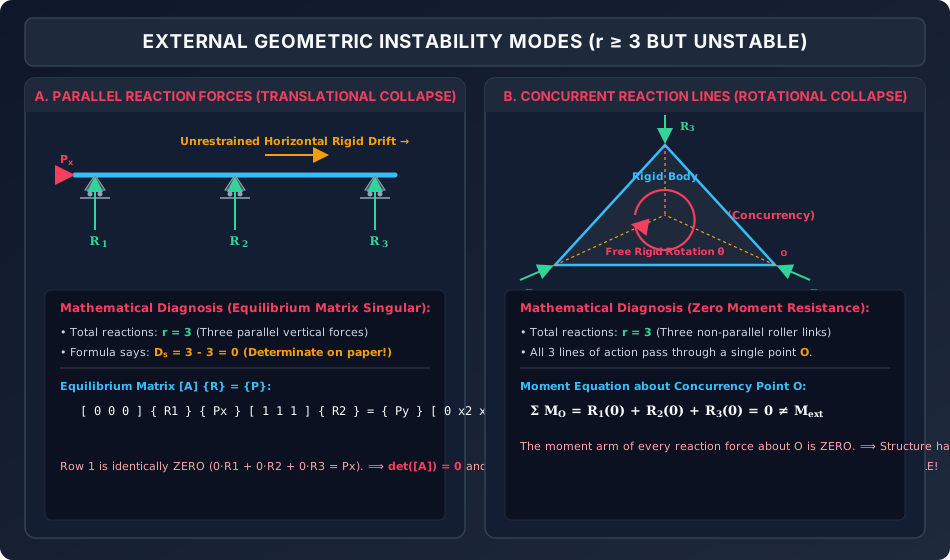
Analytical Walk-Through:
- Parallel Reactions (Panel A): A beam on 3 vertical rollers has reactions, satisfying on paper. However, because all reaction vectors are vertical (), the equilibrium matrix row for contains all zeros. Any horizontal load causes immediate translational rigid-body drift.
- Concurrent Reactions (Panel B): A rigid triangular body is supported by 3 roller links whose lines of action intersect at a single point . The moment arm of every reaction about is zero. The equilibrium matrix row for is identically zero, producing a singular matrix () and causing rotational collapse under any applied moment.
Diagram 2: Internal Instabilities, Toggle Mechanisms & Critical Forms
The graphic below depicts the toggle collapse mechanism of three collinear hinges and the parallelogram shear distortion of an unbraced truss panel.
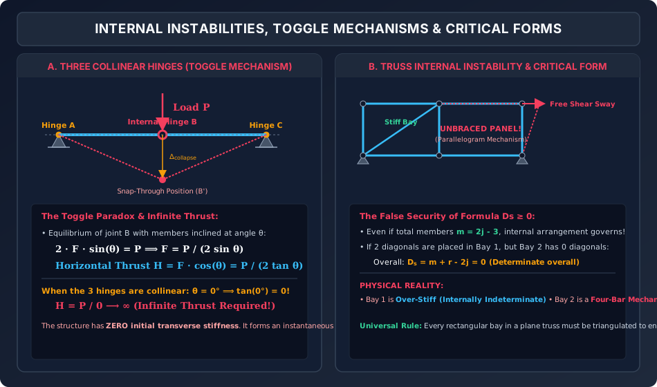
Analytical Walk-Through:
- Three Collinear Hinges (Panel A): Shows two bars pinned at and meeting at internal hinge along a straight line. Resolving vertical equilibrium reveals that horizontal thrust as . The structure possesses zero transverse stiffness and collapses into a snap-through position.
- Unbraced Truss Quadrilateral (Panel B): Demonstrates a 2-bay truss where Bay 1 is over-stiff (cross-braced) while Bay 2 is an open rectangular frame without diagonals. Although globally, Bay 2 undergoes unrestrained parallelogram shear sway.
4. Comprehensive Comparison Tables
Table 1: Complete Classification of Geometric Instabilities
| Instability Mode | Geometric Defect | Physical Consequence | Governing Equilibrium Equation Failure |
|---|---|---|---|
| Parallel Reactions | All reaction lines of action are mutually parallel | Unrestrained rigid translation perpendicular to reaction lines | cannot be satisfied |
| Concurrent Reactions | All reaction lines pass through a single point | Unrestrained rigid rotation about concurrency point | cannot be satisfied |
| Collinear Reactions | All reaction lines lie along a single axis | Body rotates freely about the reaction axis | Out-of-line moment cannot be resisted |
| Deficient Reactions | in 2D or in 3D | Overall rigid-body motion (translation or rotation) | Fewer equations than rigid degrees of freedom |
| Three Collinear Hinges | Three internal/external hinges in a straight line | Toggle mechanism: infinite thrust required, zero transverse stiffness | requires |
| Unbraced Truss Bay | 4-bar unbraced polygon in a pin-jointed truss | Parallelogram shear distortion collapse of the unbraced panel | Local shear equilibrium in the bay fails |
| Critical Form (Truss) | Geometric alignment of members produces singular | Infinitesimal mechanism with zero initial elastic strain energy | despite |
Table 2: Mathematical Stability Criteria Matrix
| Structural State | Member / Support Count Criteria | Matrix Rank & Determinant Criteria | Physical Behavior |
|---|---|---|---|
| Statically Determinate & Stable | (2D truss) (2D frame) |
(full rank) |
Unique stable solution for all loads |
| Statically Indeterminate & Stable | Properly triangulated |
(full row rank) Redundant columns exist |
Stable; force distribution depends on stiffness () |
| Geometrically Unstable (Mechanism) | on paper, but improper geometry | (rank deficient) |
Free rigid-body motion or snap-through collapse |
| Statically Deficient | (2D truss) (2D beam) |
Number of columns rows Cannot have full row rank |
Immediate rigid-body motion under general loading |
5. Fully Solved Numerical Examples
Example 1: Matrix Evaluation of a Beam on Three Parallel Rollers
Problem Statement:
A horizontal steel beam of length is supported on three vertical roller supports at , , and .
An inclined concentrated load acts at at an angle to the horizontal ( to the right, downward).
- Set up the equations of static equilibrium in matrix form .
- Evaluate the determinant and rank of the equilibrium matrix .
- Explain why the structure collapses despite having reactions.
Step 1: Equilibrium Equations
The unknown support reactions are vertical forces .
- Horizontal force equilibrium:
- Vertical force equilibrium:
- Moment equilibrium about support 1 ():
Step 2: Matrix Formulation
Step 3: Determinant & Rank Calculation
Expand determinant along Row 1:
Compute rank:
- Row 1 is a row of zeros.
- Submatrix formed by rows 2 and 3:
Physical Conclusion: The matrix is rank-deficient (). The structure possesses zero capacity to resist horizontal force. The horizontal load accelerates the beam into unrestrained horizontal rigid-body motion. The structure is externally unstable.
Example 2: Three Collinear Hinges Toggle System Under Central Load
Problem Statement:
Two rigid steel links and , each of length , are pinned to rigid supports at and . An internal pin connects the two bars at .
Initially, all three pins lie exactly on the horizontal axis . A vertical concentrated downward load is placed at hinge .
- Calculate the theoretical horizontal reaction thrust in the initial collinear state ().
- If the internal pin deflects downward by , calculate the resulting horizontal thrust and axial force in the links.
- Determine the required downward sag if the allowable horizontal reaction thrust on the supports is limited to .
Step 1: Theoretical Thrust in Initial Collinear State
In the initial state, the angle of inclination with horizontal is .
The required thrust to maintain equilibrium in the initial position is infinite. The system has zero vertical load-carrying capacity and cannot stay at .
Step 2: Response at Downward Sag
Horizontal half-span: .
Compute horizontal thrust:
Axial compressive force in each link:
Step 3: Required Sag for
Since :
Key Takeaway: For the horizontal thrust to remain below , hinge must sag by a massive ( of half-span!). This proves that three collinear hinges cannot function as a structural support system without severe geometric snap-through.
Example 3: Two-Bay Truss with Unbraced Quadrilateral Panel
Problem Statement:
A two-bay plane truss has joints:
- Bottom joints:
- Top joints:
- Left support is pinned ().
- Right support is a roller support (). Total reactions .
- Bay 1 () contains two diagonal cross-braces ( and ).
- Bay 2 () contains zero diagonal braces.
- Count the total members and check the global determinacy formula .
- Analyze the local stability of Bay 1 and Bay 2.
- Formulate the mechanism deformation mode of Bay 2.
Step 1: Global Formula Check
- Number of joints:
- Number of members:
- Bottom chord: ()
- Top chord: ()
- Vertical posts: ()
- Bay 1 diagonals: ()
- Bay 2 diagonals:
- Total members:
- Support reactions: .
- Evaluate global indeterminacy:
Step 2: Physical Diagnosis of Local Instability
On paper, falsely suggests that the truss is statically determinate and stable.
- Bay 1 Analysis:
- Joints: , Members: perimeter diagonals .
- Required members for determinate box: .
- Bay 1 has members: redundant bar (Over-stiff, ).
- Bay 2 Analysis:
- Joints: , Members: perimeter diagonals .
- Required members for determinate box: .
- Bay 2 has only members: member deficient ().
Step 3: Mechanism Mode
Bay 2 is a four-bar linkage (parallelogram linkage). Under any lateral load applied at , the angle between members and changes freely without any change in bar lengths:
Joints and sway laterally as a rigid mechanism. The truss collapses locally in Bay 2, confirming that is a meaningless indicator when internal triangulation is missing.
6. Common Misconceptions & High-Yield Exam Traps
Misconception 1: "A structure with is always stable"
- The Trap: Answering "Determinate and Stable" immediately upon finding .
- Correction: You must inspect the geometry! If reactions are parallel or concurrent, or if internal triangulation is missing, the structure is an unstable mechanism despite .
Misconception 2: "Three roller supports provide , so they are as stable as a pin + roller"
- The Trap: Assuming that any support combination giving is adequate.
- Correction: Three parallel rollers can only resist forces along one axis. They provide zero restraint against translation perpendicular to the roller axes ( failure). Stable 2D support requires non-parallel, non-concurrent reactions.
Misconception 3: "Three hinges in a line can carry vertical load once the load is small"
- The Trap: Believing that a tiny load will not cause collapse in three collinear hinges.
- Correction: The horizontal thrust formula is . Even for an infinitesimal load , if , . The system has zero initial tangent stiffness.
Misconception 4: "Adding a member anywhere in an unstable truss makes it stable"
- The Trap: Adding an extra diagonal to Bay 1 in Example 3 to cure the instability in Bay 2.
- Correction: Adding a bar to Bay 1 merely increases the redundancy of Bay 1 (), leaving Bay 2 as an unbraced mechanism! The stabilizing member must be placed directly inside the deficient kinematic sub-assemblage.
Misconception 5: "Concurrent reaction instability only occurs if reactions intersect at a physical support"
- The Trap: Assuming concurrency only matters if rollers meet at the same location.
- Correction: The intersection point of the reaction lines of action can be located far outside the physical boundary of the structure in empty space! If all reaction vectors point towards that external point , the entire structure rotates freely about .
7. Previous Years Questions & Benchmark Solutions
Question 1 (GATE CE)
Problem: A plane frame is supported on three rollers whose normal lines of action intersect at a common point . The structure is:
(A) Statically determinate and stable
(B) Statically indeterminate and stable
(C) Geometrically unstable against rotation about point
(D) Geometrically unstable against translation along the normal axis
Solution:
- Each roller reaction passes directly through point .
- The perpendicular distance (moment arm) from point to every reaction force is zero ().
- The sum of moments of all reaction forces about point is identically zero:
- Therefore, the support reactions cannot resist any applied external moment about point . The frame undergoes free rigid-body rotation about .
Correct Answer: (C) Geometrically unstable against rotation about point O.
Question 2 (UPSC ESE)
Problem: A three-hinged arch has its two abutment hinges at the same level and a third crown hinge located on the line joining the two abutments. Under a central concentrated vertical load , the horizontal thrust at the abutments will be:
(A) Zero
(B)
(C)
(D) Infinitely large
Solution:
- For a three-hinged arch of span and crown rise , the horizontal thrust is:
- If the crown hinge lies on the line joining the two abutment hinges, the rise is zero ().
- Substitute :
Correct Answer: (D) Infinitely large.
Question 3 (SSC JE / State AE)
Problem: If a plane truss has members and joints, the minimum number of members required for internal stability is:
(A)
(B)
(C)
(D)
Solution: For a 2D pin-jointed truss, internal stability requires complete triangulation, establishing the condition:
The minimum number of members is .
(In 3D space trusses, the minimum is ).
Correct Answer: (B) 2j - 3.
8. Quick Revision Formulas & Key Exam Takeaways
╔═══════════════════════════════════════════════════════════════════════════════╗
║                   GEOMETRIC STABILITY FORMULA CHEAT SHEET                     ║
╠═══════════════════════════════════════════════════════════════════════════════╣
║ 1. Golden Stability Axiom:                                                    ║
║    Ds ≥ 0 is NECESSARY, but NOT SUFFICIENT for stability!                     ║
║                                                                               ║
║ 2. Three External Instability Rules (2D):                                     ║
║    • NO Parallel Reactions:    All reactions cannot be parallel (det[A] = 0)  ║
║    • NO Concurrent Reactions:  All reaction lines cannot pass through 1 point ║
║    • NO Collinear Reactions:   Reactions cannot lie along a single line       ║
║    • Minimum Reactions:        r ≥ 3 (2D) and r ≥ 6 (3D)                      ║
║                                                                               ║
║ 3. Internal Instability Rules:                                                ║
║    • Three Collinear Hinges:   Toggle mechanism (H = P / [2 tan θ] → ∞)       ║
║    • Truss Triangulation:      Every bay must be triangulated (m ≥ 2j - 3)    ║
║    • No Unbraced 4-Bar Panels: Parallelogram shear collapse mechanism         ║
║                                                                               ║
║ 4. Equilibrium Matrix Criterion:                                              ║
║    [A] {F} = {P}                                                              ║
║    • Stable:                  rank([A]) = 2j (or 3j), det([A]) ≠ 0            ║
║    • Mechanism/Critical Form: det([A]) = 0, rank([A]) < full rank             ║
║                                                                               ║
║ 5. Minimum Members for Internal Stability:                                    ║
║    • 2D Plane Truss:  m_min = 2j - 3                                          ║
║    • 3D Space Truss:  m_min = 3j - 6                                          ║
╚═══════════════════════════════════════════════════════════════════════════════╝