Two-Hinged Stiffening Girders and Cable Mechanics: Indeterminacy, Influence Lines, and Temperature Stresses
In this chapter (4 topics)
On this page
- 1. Executive Summary & Structural Concept
- 2. Statics, Kinematics & Degree of Indeterminacy (Ds = 1)
- 2.1 Degree of Static Indeterminacy
- 2.2 Sign Conventions & Internal Force Signatures
- 3. Energy Formulation via Castigliano’s Second Theorem
- 3.1 Total Internal Strain Energy
- 3.2 Compatibility Condition
- 3.3 The Inextensible Cable Assumption
- 4. Closed-Form Solutions for Standard Loadings
- Case A: Uniformly Distributed Load (w) Across the Entire Span (0 ≤ x ≤ L)
- Case B: Concentrated Point Load (W) at Distance a = kL from Left Support
- Case C: Uniformly Distributed Load (w) Over Half Span (0 ≤ x ≤ L/2)
- 5. Influence Line Diagrams (ILD) for Two-Hinged Stiffening Girders
- 5.1 Influence Line for Cable Thrust H (ηH)
- 5.2 Influence Line for Girder Bending Moment at Section x (ηM)
- 5.3 Influence Line for Girder Shear Force at Section x (ηV)
- 6. Temperature Stresses & Uniform Sagging/Hogging Moments
- 6.1 Mechanics of Thermal Deformation
- 6.2 Induced Thermal Bending Moment (Mtemp)
- 7. Cable Elastic Stretch & Finite Flexural Rigidity Corrections
- 8. Solved Numerical Examples (Rigorous 3-Problem Set)
- Problem 1: Two-Hinged Stiffening Girder Under Midspan Point Load
- Problem 2: Two-Hinged Stiffening Girder Under Partial-Span UDL
- Problem 3: Temperature Variation and Resulting Flexural Stresses
- 9. Three-Hinged vs. Two-Hinged Stiffening Girders: Definitive Comparative Matrix
- 10. Common Engineering Misconceptions & Exam Pitfalls
- Misconception 1: "The bending moment diagram for temperature rise in a two-hinged girder is parabolic."
- Misconception 2: "Temperature rise causes hogging in a two-hinged suspension bridge."
- Misconception 3: "Under full UDL, the two-hinged girder develops bending moments because it is indeterminate."
- 11. Professional Design Practice, Aerodynamic Stability & Historic Bridge Failures
- 11.1 The Tacoma Narrows Bridge Disaster (1940)
- 11.2 Modern Design Standards (IRC:SP:47 & Eurocode 1)
- 12. Comprehensive Summary, Formula Sheet & Fast-Revision Checkpoints
- Master Formula Sheet
- Fast-Revision Key Takeaways
1. Executive Summary & Structural Concept
In suspension bridge engineering, the two-hinged stiffening girder represents the predominant structural form for medium-to-long span bridges carrying high-speed highway or railway corridors. While the classical three-hinged stiffening girder () provides static determinacy by incorporating a pin at midspan, that central hinge introduces significant practical disadvantages:
- Kinematic Discontinuity: The central hinge creates a sharp angular cusp (slope discontinuity) under moving wheel loads, causing severe impact vibrations and excessive joint wear.
- Reduced Aerodynamic Rigidity: The absence of midspan bending continuity drastically lowers the overall torsional and vertical flexural natural frequencies, making three-hinged decks vulnerable to aerodynamic flutter and wind-induced galloping.
By eliminating the central hinge, the stiffening girder becomes a single continuous beam simply supported at its ends ( and ). The resulting system is statically indeterminate to the first degree (), with the horizontal cable tension serving as the redundant force.
Three-Hinged Girder (Ds = 0)                   Two-Hinged Girder (Ds = 1)
• Center hinge: MC ≡ 0                         • Continuous: MC ≠ 0
• Zero thermal stresses in girder              • Constant thermal sagging moment M_temp across span
• Severe joint fatigue & lower stiffness       • High aerodynamic rigidity & superior ride quality
Under gravity loads, the continuous girder distributes wheel loads across the vertical hangers to the main cable. Under ambient temperature variations, however, the continuous girder is forced into a curved profile by the dipping or rising cable, developing substantial secondary thermal bending moments that govern cross-sectional sizing.
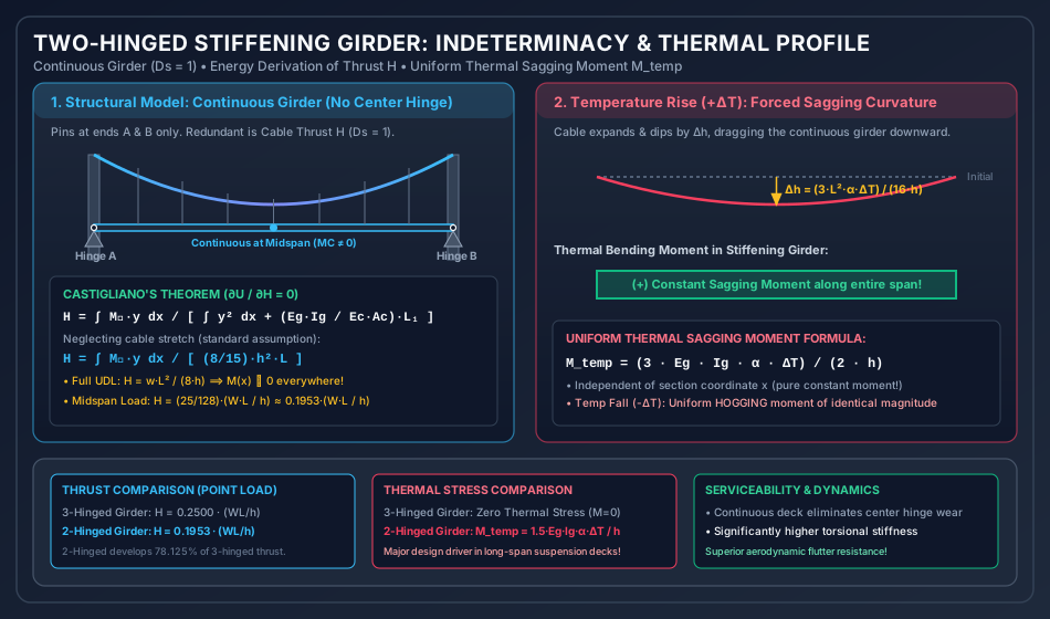
2. Statics, Kinematics & Degree of Indeterminacy ()
2.1 Degree of Static Indeterminacy
Consider a suspension bridge with a two-hinged stiffening girder of span and a parabolic main cable of central dip :
- The cable is supported on towers at and and anchored to unyielding abutments.
- The stiffening girder is supported on vertical hinges/rollers at ends and ( reaction components for planar beam equilibrium: ).
- The cable and girder are interconnected by a continuous sheet of vertical hangers.
- Because there is no internal hinge along the girder span (), the entire system possesses:
- Primary Redundant: The horizontal component of cable tension, .
2.2 Sign Conventions & Internal Force Signatures
For any cross-section measured from the left support:
- Net Bending Moment in Girder ():
where:
- is the bending moment in an equivalent simply supported beam under the applied external gravity loads.
- is the vertical ordinate of the parabolic cable profile.
- represents the relieving hogging moment produced by the upward hanger pull transmitted to the cable.
- Positive sign (): Sagging moment (compression on top flange, tension on bottom flange).
- Negative sign (): Hogging moment (tension on top flange, compression on bottom flange).
- Net Vertical Shear Force in Girder (): where is the local slope of the parabolic cable.
3. Energy Formulation via Castigliano’s Second Theorem
To determine the redundant cable thrust , we apply Castigliano’s Second Theorem (the Principle of Minimum Strain Energy).
3.1 Total Internal Strain Energy
The total elastic strain energy stored in the combined suspension system consists of:
- Flexural strain energy of the continuous stiffening girder ():
- Axial tensile strain energy of the main cable ():
- Axial tensile strain energy of the vertical hangers (): Generally negligible () due to short hanger lengths and high hanger stiffness.
3.2 Compatibility Condition
Differentiating total strain energy with respect to the redundant horizontal thrust :
Evaluating the girder contribution:
Evaluating the cable contribution:
where .
Equating the sum to zero:
Solving explicitly for the redundant horizontal cable thrust :
3.3 The Inextensible Cable Assumption
In typical long-span bridge engineering, the axial stiffness of the massive steel cable () is enormous compared to the flexural stiffness of the stiffening girder (). Setting the cable stretch parameter :
Recall from two-hinged arch mechanics that for a parabolic profile , the denominator evaluates to:
Therefore, the fundamental equation for horizontal thrust in a two-hinged stiffening girder is:
4. Closed-Form Solutions for Standard Loadings
Case A: Uniformly Distributed Load () Across the Entire Span ()
- Simply supported beam moment:
- Numerator:
- Horizontal Thrust:
- Profound Structural Result: Under a full UDL, the cable carries of the external load; the stiffening girder experiences zero bending moment and zero shear force everywhere along its span!
Case B: Concentrated Point Load () at Distance from Left Support
-
Evaluating the integral where is triangular:
-
Dividing by :
or in terms of physical distance :
-
Midspan Concentrated Load ():
Comparative Analysis with Three-Hinged Girder:
- In a three-hinged girder: .
- Ratio: Because the continuous girder carries a portion of the concentrated load in bending, the cable thrust is reduced by approximately compared to the three-hinged case!
Case C: Uniformly Distributed Load () Over Half Span ()
By symmetry and linear superposition:
5. Influence Line Diagrams (ILD) for Two-Hinged Stiffening Girders
Influence lines are indispensable for determining the critical positions of moving vehicular live loads (wheel trains or lane loading) that maximize internal forces.
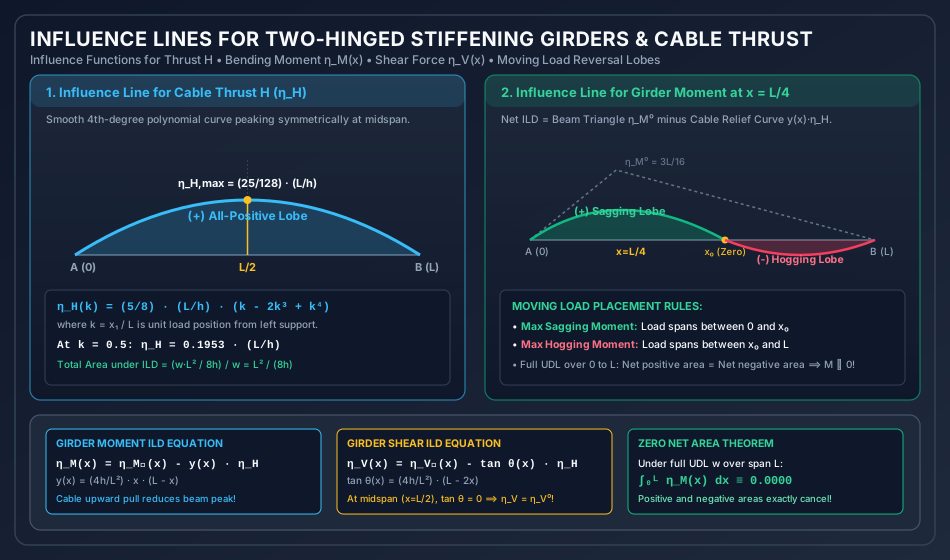
5.1 Influence Line for Cable Thrust ()
When a unit concentrated load () traverses the span at distance from the left support:
- Geometric Properties:
- is a smooth, continuous 4th-degree polynomial curve.
- Zero at both supports: .
- Symmetric about midspan, reaching its maximum at :
- The ordinate is strictly positive throughout (); any downward gravity load anywhere on the deck increases cable tension.
- Total area under the ILD: (Multiplying this area by a full UDL yields , confirming exact static consistency!)
5.2 Influence Line for Girder Bending Moment at Section ()
The net moment at section is:
Applying a unit moving load ():
where:
- is the standard triangular ILD for simply supported beam moment at , with peak ordinate at .
- is a smooth 4th-degree subtractive curve whose maximum ordinate occurs at midspan ().
Net ILD Profile & Reversal Lobes:
Because the subtractive curve is smooth while the beam ILD is sharply peaked at :
- Positive (Sagging) Lobe: Underneath and adjacent to section , , creating a positive sagging lobe.
- Negative (Hogging) Lobe: In the opposite half of the span, drops toward zero while remains positive. The net ordinate becomes negative (hogging).
- Inflection Point (): The point where the curve crosses the baseline ().
Critical Live Load Placement Rules:
- To produce maximum sagging moment at section : Load the positive lobe (from to ).
- To produce maximum hogging moment at section : Load the negative lobe (from to ).
- Under a full UDL from to : The positive area exactly equals the negative area (), producing zero net moment!
5.3 Influence Line for Girder Shear Force at Section ()
where:
- is the simply supported beam shear ILD, with a vertical step discontinuity of at .
- is constant for a given section .
- At midspan (), the cable slope is zero (), so the shear ILD in the girder is identical to a straight simply supported beam!
6. Temperature Stresses & Uniform Sagging/Hogging Moments
Unlike three-hinged stiffening girders where temperature variations cause free rotation at the center pin (), a two-hinged stiffening girder develops severe bending stresses under temperature changes.
6.1 Mechanics of Thermal Deformation
- When ambient temperature rises by , the steel cable expands along its length:
- The increase in central dip of the cable is:
- Because the vertical hangers connect the cable directly to the continuous stiffening girder, the downward sag of the cable pulls the girder down, imposing a vertical displacement profile:
6.2 Induced Thermal Bending Moment ()
From Euler-Bernoulli beam theory, the induced bending moment is proportional to the second derivative of the forced deflection:
Differentiating :
Substituting back into the moment formula:
Now substitute the cable dip formula :
Extraordinary Structural Characteristics:
- Uniform Moment Throughout Span: Notice that the variable completely cancels out! is strictly constant along the entire length of the bridge (a flat, uniform moment diagram)!
- Sign of Thermal Moments:
- Temperature Rise (): The cable drops forces the girder into downward sagging curvature uniform positive (sagging) moment!
- Temperature Fall (): The cable contracts and lifts forces the girder into upward hogging curvature uniform negative (hogging) moment!
- Contrast with Two-Hinged Arch:
- In a two-hinged arch, temperature rise produces hogging moments that peak parabolically at the crown.
- In a two-hinged suspension bridge, temperature rise produces a constant sagging moment everywhere!
7. Cable Elastic Stretch & Finite Flexural Rigidity Corrections
When the elasticity of the main cable is considered, the horizontal thrust formula derived in Section 3.2 is:
where .
- Impact of Cable Stretch: The positive term increases the denominator, which reduces the horizontal thrust by approximately .
- Consequence for Girder Moments: Because , a reduction in reduces the relieving hogging moment, thereby increasing net sagging bending moments in the stiffening girder under live loads.
8. Solved Numerical Examples (Rigorous 3-Problem Set)
Problem 1: Two-Hinged Stiffening Girder Under Midspan Point Load
Statement:
A two-hinged suspension bridge stiffening girder has a span and a central cable dip . A single concentrated live load is placed at midspan (). Neglecting cable stretch:
- Calculate the horizontal cable thrust .
- Determine the bending moment in the girder at midspan () and at quarter-span ().
- Compare the midspan moment with that of an equivalent three-hinged stiffening girder.
Solution:
Step 1: Horizontal Cable Thrust Computation
With load at midspan ():
Step 2: Bending Moment at Midspan ()
- Simply supported beam moment:
- Cable vertical ordinate at midspan:
- Cable relieving moment:
- Net Bending Moment in Girder:
Step 3: Bending Moment at Quarter-Span ()
- Simply supported beam moment:
- Cable vertical ordinate at quarter-span:
- Cable relieving moment:
- Net Bending Moment in Girder:
Step 4: Comparison with Three-Hinged Stiffening Girder
- In a three-hinged stiffening girder, the midspan contains a hinge, forcing .
- In the two-hinged girder, midspan continuity generates a significant sagging moment of , but provides superior aerodynamic stiffness.
Problem 2: Two-Hinged Stiffening Girder Under Partial-Span UDL
Statement:
A two-hinged stiffening girder of span and dip carries a uniformly distributed live load over the left half of the span ().
Find:
- The horizontal cable thrust .
- The bending moments in the girder at (loaded quarter point) and (unloaded quarter point).
Solution:
Step 1: Horizontal Cable Thrust
By linear superposition:
Step 2: Simply Supported Beam Reactions Under Half UDL
Total load , acting at . Taking moments about support :
Step 3: Moments at Quarter Points
Cable ordinate at and :
Cable relieving moment:
- At (Loaded Half):
- At (Unloaded Half):
(Notice the exact anti-symmetry: sagging vs hogging! At midspan , ).
Problem 3: Temperature Variation and Resulting Flexural Stresses
Statement:
A two-hinged suspension bridge has a span and central dip . The stiffening girder has flexural rigidity and an overall depth (). The coefficient of thermal expansion is .
- If temperature rises by , compute the increase in cable dip .
- Determine the uniform bending moment induced throughout the stiffening girder.
- Calculate the maximum flexural bending stress induced in the girder.
Solution:
Step 1: Cable Dip Increase
Step 2: Induced Uniform Thermal Moment
Step 3: Maximum Flexural Stress in Girder Flanges
(A significant stress that must be added to dead and live load combinations!).
9. Three-Hinged vs. Two-Hinged Stiffening Girders: Definitive Comparative Matrix
| Criterion / Parameter | Three-Hinged Stiffening Girder | Two-Hinged Stiffening Girder |
|---|---|---|
| Degree of Indeterminacy () | (Determinate) | (Indeterminate) |
| Midspan Bending Moment () | Identically zero () | Non-zero () |
| Thrust Under Midspan Load () | ( of 3-hinged) | |
| Thrust Under Full UDL () | ||
| Moment Under Full UDL | everywhere | everywhere |
| Temperature Sensitivity | Zero thermal stress in girder | Constant uniform moment |
| Support Settlement Sensitivity | Insensitive to abutment settlement | Sensitive; foundation spread induces moments |
| Aerodynamic & Torsional Rigidity | Low; vulnerable to flutter | High; continuous deck enhances stability |
| Riding Comfort & Maintenance | Poor (grade break & pin wear at midspan) | Superior (continuous road profile, low maintenance) |
| Mathematical Complexity | Solved by pure statics | Requires energy methods or ILD integration |
10. Common Engineering Misconceptions & Exam Pitfalls
Misconception 1: "The bending moment diagram for temperature rise in a two-hinged girder is parabolic."
Correction: This is the most dangerous exam trap! Because the forced deflection curve is parabolic (), its second derivative is a constant (). Therefore, the induced thermal bending moment is strictly constant along the entire length of the span! It is a flat horizontal line, not a parabola!
Misconception 2: "Temperature rise causes hogging in a two-hinged suspension bridge."
Correction: Students often confuse arches with suspension bridges. In a two-hinged arch, temperature rise causes the rib to expand against rigid hinges, inducing inward thrust and hogging. In a suspension bridge, temperature rise causes the cable to expand and sag downward, dragging the continuous girder down and inducing a sagging moment!
Misconception 3: "Under full UDL, the two-hinged girder develops bending moments because it is indeterminate."
Correction: Under a uniformly distributed load over the entire span, the funicular curve of the cable matches the parabolic profile exactly. The upward pull of the hangers perfectly balances the downward load at every point along the span. Thus, and throughout the girder, exactly as in the determinate three-hinged case!
11. Professional Design Practice, Aerodynamic Stability & Historic Bridge Failures
11.1 The Tacoma Narrows Bridge Disaster (1940)
The original Tacoma Narrows Bridge ("Galloping Gertie") utilized a two-hinged shallow plate girder deck ( depth for an span, span-to-depth ratio ). On November 7, 1940, in a moderate wind:
- The solid plate girders shed alternating vortices (von Kármán vortex shedding), exciting vertical oscillations.
- As amplitudes grew, aerodynamic forces coupled with structural motion, shifting from vertical bending into a destructive torsional flutter mode.
- The lack of torsional rigidity in the shallow two-hinged plate girder led to catastrophic collapse.
11.2 Modern Design Standards (IRC:SP:47 & Eurocode 1)
- Deep Stiffening Trusses: Open steel truss girders allow wind to pass freely through the structure, drastically reducing aerodynamic lift and drag coefficients.
- Streamlined Aerodynamic Box Girders: Modern record-breaking suspension bridges (e.g., Severn Bridge, UK; Bosphorus Bridge, Turkey; Humber Bridge, UK) utilize hollow aerodynamic steel orthotropic box girders with sharp leading-edge wind fairings that suppress vortex shedding.
- Hold-Down Bearings: As demonstrated in Problem 2, partial-span live loads generate upward uplift forces () at the unloaded abutment. Heavy prestressed hold-down anchorage ties are mandatory at tower bearings.
12. Comprehensive Summary, Formula Sheet & Fast-Revision Checkpoints
Master Formula Sheet
Fast-Revision Key Takeaways
- A two-hinged stiffening girder is statically indeterminate to the 1st degree ().
- Eliminating the center pin improves aerodynamic flutter stability and eliminates slope discontinuities.
- Under full UDL across the span, the girder has zero bending moment everywhere ().
- Under a midspan point load, cable thrust is , which is of that in a three-hinged girder.
- Temperature rise causes a uniform sagging moment of magnitude that is strictly constant across the entire span.
- The influence line for cable thrust is a smooth 4th-degree curve peaking at midspan with ordinate .
- The influence line for girder moment exhibits a positive sagging lobe under the section and a negative hogging lobe in the opposite half span.