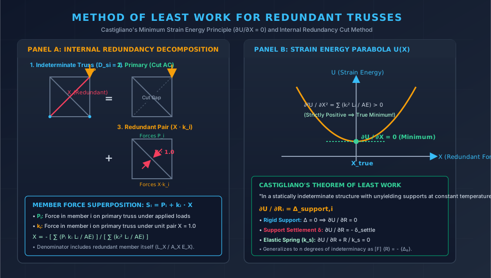
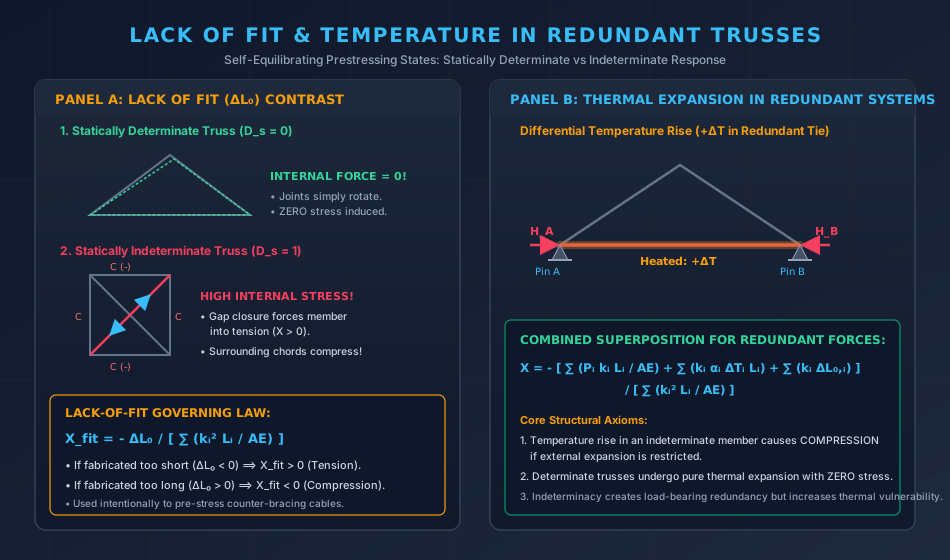
In structural engineering, pin-jointed trusses are frequently designed with static indeterminacy (Ds>0) rather than as strictly determinate systems (m=2j−3 in 2D or 3j−6 in 3D). Indeterminacy offers critical structural advantages:
Structural Redundancy & Alternate Load Paths: If any single member suffers damage or fails (e.g., from fatigue, vehicle impact, or extreme seismic events), an indeterminate truss redistributes internal forces through alternative load paths, preventing catastrophic progressive collapse.
Enhanced Stiffness & Deflection Control: Redundant members increase overall structural stiffness, reducing live-load deflections and dynamic vibrations.
However, static indeterminacy introduces distinct engineering challenges:
Thermal Stresses: Statically determinate trusses expand and contract freely without developing internal stresses; indeterminate trusses develop significant thermal forces when restrained.
Fabrication Tolerances & Lack of Fit: In an indeterminate truss, members fabricated slightly too long or too short cannot be inserted without being forced into place, locking in high initial residual self-stresses.
Support Settlement Sensitivity: Differential settlement of foundations induces substantial secondary forces.
The Method of Least Work (derived from Alberto Castigliano's Second Theorem) provides the classic energy-based force method to solve indeterminate trusses under combined mechanical loads, initial lack of fit, temperature changes, and elastic support settlements.
2. Castigliano's Theorem of Least Work
2.1 Derivation from Castigliano's Second Theorem
Recall Castigliano's Second Theorem for a linearly elastic structure:
∂Ri∂U=Δi
where U is total internal strain energy, Ri is a redundant reaction or internal member force, and Δi is the corresponding displacement at coordinate i.
Unyielding / Rigid Supports (Δi=0):
If the redundant Ri is an external reaction at an unyielding, rigid support, the displacement along Ri is identically zero (Δi=0). Thus:
∂Ri∂U=0
Castigliano's Theorem of Least Work:In any statically indeterminate linearly elastic structure with unyielding supports at constant temperature, the redundant reactions take on values that minimize the total strain energy stored in the structure.
Yielding / Settling Supports (Δi=−δsettle):
If support i yields or settles by δsettle in the opposite direction of assumed reaction Ri:
∂Ri∂U=−δsettle
Elastic / Flexible Spring Supports:
If the redundant reaction Ri rests on an elastic support (e.g., a pile group, neoprene pad, or soil spring) with linear stiffness ks:
The total strain energy of the combined system is Utotal=Ustructure+Uspring=Ustructure+2ksRi2.
Minimizing total energy: ∂Ri∂Utotal=0⟹∂Ri∂Ustructure+ksRi=0:
∂Ri∂Ustructure=−ksRi
2.2 Proof of True Minimization
Differentiating the total strain energy a second time:
∂Ri2∂2U=j=1∑mAjEjkj2Lj
Because kj2≥0, length Lj>0, and axial rigidity AjEj>0, the second derivative is strictly positive (∂Ri2∂2U>0). This confirms that the stationary point is mathematically a true global minimum, never a maximum or saddle point.
3. Analysis of Externally Indeterminate Trusses (Dse>0)
An externally indeterminate truss has more support constraints than the equations of static equilibrium can resolve (r>3 in 2D).
   P-Load ↓
   ===========================
   ▲            ▲            ▲
   A (Pin)      B (Roller)   C (Roller)   ---> D_se = 4 - 3 = 1
Step-by-Step Procedure:
Identify Redundant Reaction: Choose one support reaction as redundant R (e.g., vertical reaction RB at middle support).
Form the Primary Determinate Base Structure: Remove the redundant restraint (remove support B), leaving a stable, determinate simply supported truss spanning from A to C.
P-System (Real Loads on Primary Structure): Calculate member forces Pi in the primary structure under external applied loads only (R=0).
k-System (Unit Redundant on Primary Structure): Remove all external loads and apply a unit virtual load (R=1.0) at support B in the direction of the redundant. Calculate member forces ki.
Superposition of Member Forces:Si=Pi+kiR
Apply Least Work:∂R∂U=i=1∑mAiEiSiLi(∂R∂Si)=i=1∑mAiEi(Pi+kiR)Liki=0i=1∑mAiEiPikiLi+Ri=1∑mAiEiki2Li=0R=−∑i=1mAiEiki2Li∑i=1mAiEiPikiLi=−fBBΔB0
Where:
ΔB0=∑AiEiPikiLi: Downward deflection of joint B in the primary structure under external loads.
fBB=∑AiEiki2Li: Flexibility coefficient (upward displacement of joint B due to unit upward force R=1.0).
4. Analysis of Internally Indeterminate Trusses (Dsi>0)
An internally indeterminate truss possesses redundant members that form closed statically indeterminate loops (e.g., cross-braced panels where m>2j−r).
   Actual Indeterminate Truss:          Primary Cut Truss + Redundant Pair:
         D ------- C                          D ------- C
         | \     / |                          |       / |
         |   \ /   |                          |      /  |
         |    X    |          ====>           |     /   |   +  X · (Unit Pair)
         |   / \   |                          |    /    |
         | /     \ |                          |   /     |
         A ------- B                          A ------- B
        (Both Diagonals)                     (Diagonal AC Cut)
The Cut Member Method:
Select Redundant Member: Choose an internal member (such as diagonal AC) and denote its unknown axial force as X (assumed in tension).
Cut the Redundant Member: Make a fictitious transverse cut across member AC. The remaining system is a statically determinate primary truss.
P-System: Solve the primary cut truss under actual external loads. Calculate internal forces Pi across all remaining (m−1) members. (Force in cut member AC is PAC=0).
k-System: Remove external loads. Apply a pair of equal and opposite collinear unit tensile forces (X=1.0) across the cut faces of member AC. Compute member forces ki across all members.
Note: For the redundant member AC itself, kAC=1.0.
Total Strain Energy Formulation:U=i=1∑m2AiEiSi2Li=primary∑2AiEi(Pi+kiX)2Li+2AXEXX2LX
Minimizing Strain Energy (∂X∂U=0):∂X∂U=i=1∑m−1AiEi(Pi+kiX)Liki+AXEXXLX=0i=1∑m−1AiEiPikiLi+X[i=1∑m−1AiEiki2Li+AXEXLX]=0
X=−∑i=1mAiEiki2Li∑i=1mAiEiPikiLi
Critical Rule: In the denominator sum ∑i=1mAiEiki2Li, the summation runs over all m members including the redundant member itself (where kX=1.0 and kX2=1.0).
5. Self-Straining Effects: Fabrication Lack of Fit & Temperature Changes
5.1 Fabrication Lack of Fit (ΔL0)
In practice, bridge truss members are manufactured in shops and shipped to site. If member X is fabricated with an initial length error ΔL0:
ΔL0>0: Fabricated too long
ΔL0<0: Fabricated too short
To force this imperfect member into an indeterminate truss, mechanical jacks must pull or push the connected joints together to close the gap before pinning.
Compatibility Equation:
The relative displacement of the cut faces under internal forces must exactly equal the initial gap −ΔL0:
If redundant member is fabricated too short (ΔL0<0): Xfit=−(−∣ΔL0∣)/Σ=+Tension. Pulling the gap closed stretches the member into permanent tension and forces surrounding boundary chords into compression.
If redundant member is fabricated too long (ΔL0>0): Xfit=−Compression.
Determinate Trusses:ΔL0 causes harmless rigid-body joint rotation with zero stress!
5.2 Temperature Changes (ΔT)
If member i undergoes an axial thermal expansion ΔLth,i=αiΔTiLi:
In general, a temperature rise in an internal member (ΔT>0) causes the member to expand against the stiffness of the surrounding frame, inducing compressive self-straining forces in the heated member and tensile forces in the restraining frame.
By Maxwell's Reciprocal Theorem, frs=fsr, meaning the coefficient matrix [F] is strictly symmetric and positive-definite.
7. Engineering Visualizations
7.1 Least Work & Internal Redundancy Cut Method
7.2 Lack of Fit & Temperature Self-Straining
8. Comparative Structural Matrix
Feature
Statically Determinate Truss (Ds=0)
Externally Indeterminate Truss (Dse>0)
Internally Indeterminate Truss (Dsi>0)
Equilibrium Solvability
Fully solvable by statics alone
Requires compatibility at supports
Requires internal member compatibility
Material Area Dependency
Member forces independent of A and E
Forces depend strongly on AE ratios
Forces depend strongly on AE ratios
Fabrication Error (ΔL0)
Zero internal stress; geometry shifts
Stresses induced near supports
High internal self-straining forces
Uniform Temperature Change
Free thermal expansion; zero stress
Stresses develop if supports restrain expansion
Stresses develop under differential heating
Support Settlement
Rigid body tilt; zero stress
High secondary moments and forces
Stresses develop if panel distorted
Failure of Single Member
Immediate structural collapse (mechanism)
Structure may survive if Ds≥1
Panel remains stable via counter-diagonal
9. Solved Numerical Examples with Rigorous Calculations
Example 1: Internally Indeterminate Square Cross-Braced Truss under Nodal Load
Problem Statement:
A pin-jointed square plane truss of side a=3.0 m consists of 4 outer boundary members (AB,BC,CD,DA) and 2 internal diagonal cross-braces (AC,BD). Joint A is pinned, and joint B is on a horizontal roller. All 6 members have cross-sectional area A=1000 mm2 and modulus of elasticity E=200 GPa (AE=200,000 kN).
A concentrated vertical downward load P=100 kN is applied at joint C. Using the Method of Least Work, determine:
The force in the redundant diagonal member AC.
The final forces in all 6 members of the truss.
       D (0,3) --------------- C (3,3)  ↓ P = 100 kN
         | \                 / |
         |   \             /   |
   3.0 m |     \         /     | 3.0 m
         |       \     /       |
         |         \ /         |
       A (0,0) --------------- B (3,0)
         ▲       3.0 m         ○
       (Pin)                (Roller)
Solution:
Step 1: Degrees of Static Indeterminacy:
Joints j=4; Members m=6; Support reactions r=3 (Ax,Ay,By).
Ds=m+r−2j=6+3−2(4)=1.
External indeterminacy: Dse=r−3=0.
Internal indeterminacy: Dsi=m−(2j−3)=6−(8−3)=1.
Step 2: Selection of Redundant and Primary Cut System:
Choose diagonal member AC as the redundant with internal tensile force X. Cut member AC.
The primary determinate truss has 5 members (AB,BC,CD,DA,BD).
Step 3: Primary System Forces (Pi) under External Load P=100 kN at C:
External support reactions:
∑MA=0⟹By(3.0)−100(3.0)=0⟹By=100 kN↑∑Fy=0⟹Ay+100−100=0⟹Ay=0∑Fx=0⟹Ax=0
Joint equilibrium on primary structure:
Joint C: Connected only to CD (horizontal) and CB (vertical).
∑Fy=0⟹PCB−100=0⟹PCB=−100 kN (Compression)∑Fx=0⟹PCD=0
Joint D: Connected to DA, CD, and diagonal DB.
Since PCD=0, ∑Fx=0⟹PDBcos45∘=0⟹PDB=0.
Then ∑Fy=0⟹PDA=0.
Joint A: With Ax=Ay=0 and PDA=0, PAB=0.
Cut redundant member: PAC=0.
In the primary cut structure, load P=100 kN travels directly down post BC into roller B. All other members have Pi=0.
Step 4: Virtual System Forces (ki) under Unit Tension Pair X=1.0 in AC:
Apply unit tension X=1.0 at cut faces of member AC (pulling joint A toward C, and joint C toward A):
Equilibrium Check at Joint C:
Vertical: SBC+SACsin45∘+P=−89.645+(−14.645)(0.707107)−(−100)=−89.645−10.355+100=0.000 kN✓
Example 2: Initial Lack-of-Fit Self-Straining in a Redundant Truss
Problem Statement:
Consider the same square cross-braced truss from Example 1 (a=3.0 m,A=1000 mm2,E=200 GPa,AE=200,000 kN). No external loads act on the truss (P=0). However, diagonal member AC was fabricated 3.0 mm too short (ΔL0=−3.0 mm=−0.003 m) and forced into position during erection.
Calculate the self-straining internal forces locked into all 6 members.
Solution:
Step 1: Formula for Lack-of-Fit Self-Straining:
Because Pi=0 everywhere, the numerator contains only the lack-of-fit gap ΔL0:
Right Post BC: SBC=−0.7071×41.421=−29.29 kN (Compression)
Top Chord CD: SCD=−0.7071×41.421=−29.29 kN (Compression)
Left Post DA: SDA=−0.7071×41.421=−29.29 kN (Compression)
Physical Conclusion: Forcing a short diagonal to close a mere 3 mm gap generates over 41 kN of permanent prestressing tension in both diagonals and squeezes all four boundary chords into 29.3 kN of compression, even with zero external payload on the structure!
Example 3: Two-Span Continuous Truss on Elastic Spring Support
Problem Statement:
A continuous roof truss spans across two equal bays of 12 m each (24 m total length), resting on three supports: pinned at A, roller at C, and a central redundant roller support at B. The primary determinate base structure (with support B removed) exhibits a downward central deflection under dead load of ΔB0=24.0 mm. A unit upward force applied at joint B produces an upward deflection of fBB=0.40 mm/kN.
Calculate the upward reaction force RB provided by the center support if:
Support B is completely rigid and unyielding.
Support B rests on an elastic foundation / spring of stiffness ks=50.0 kN/mm.
Solution:
Step 1: Case 1 — Rigid Support (ΔB=0):
By the Method of Least Work / Consistent Deformations:
Engineering Comparison:
The elastic flexibility of the foundation reduces the reaction demand on the central column from 60.00 kN to 57.14 kN (a 4.76% reduction), shedding load into the stiffer outer bridge abutments.
10. Common Pitfalls, Exam Traps & Misconceptions
10.1 Omitting the Redundant Member's Flexibility from the Denominator
Trap: Forgetting to add AXEXLX to ∑AEki2Li when solving an internally redundant cut truss.
Rule: The redundant member is an integral elastic component of the structure. Its own flexibility represents its elongation (kX=1.0⟹kX2=1.0). If omitted, the redundant force will be drastically overestimated.
10.2 The Sign Convention Trap in Lack of Fit
Trap: Assuming ΔL0 for a "too short" member is positive.
Rule: A member fabricated too short has ΔL0<0. The formula contains a minus sign:
Xfit=−∑AEk2LΔL0=−Σ(−∣ΔL0∣)=+Tension
Always check that a short member must be pulled to fit, guaranteeing tensile stress.
Trap: Calculating high thermal stresses in a simply supported roof truss under uniform temperature rise.
Correction: In a statically determinate truss, thermal expansion causes free geometric enlargement; internal forces are identically zero. Thermal stresses arise only when external supports or internal redundant members resist expansion.
10.4 The Counter-Bracing Assumption Trap
Trap: Analyzing a cross-braced panel with slender tie rods assuming both diagonals carry compression.
Rule: Slender diagonals with high slenderness ratio (λ>250) buckle elastically under minimal compression and cannot sustain compressive loads. In counter-braced trusses, the compression diagonal drops out, and the tension diagonal carries the entire shear load determinately (X=V/sinθ).
11. Codal Provisions & Master Formula Sheet
11.1 IS 800:2007 Codal Requirements for Redundant Trusses
Clause 7.3 & Clause 12 (Bracing Systems): Cross-bracing in industrial building bays and bridge portals must be designed considering initial prestressing and temperature variations.
Clause 3.8 (Slenderness Limits): For members normally acting as ties but subject to reversal of stress due to wind or earthquake: λ≤350. For tension members pretensioned to avoid sag: λ≤400.
11.2 Master Formula Quick-Reference Sheet
Redundancy ConditionLeast Work Axiom (Rigid Support)Support Settlement δsettleElastic Spring Support ksExternally Redundant Reaction RInternally Redundant Member Force XInitial Lack of Fit ΔL0Combined Mechanical + Thermal + LackMulti-Degree Indeterminacy MatrixGoverning Least Work Equation∂R∂U=0(Minimum Total Strain Energy)∂R∂U=−δsettle∂R∂U+ksR=0⟹R=fRR+1/ksΔ0R=−∑i=1mAiEiki2Li∑i=1mAiEiPikiLiX=−∑i=1mAiEiki2Li∑i=1mAiEiPikiLi(sum includes redundant member!)Xfit=−∑i=1mAiEiki2LiΔL0(ΔL0<0⟹X>0 Tension)X=−∑AEk2L∑AEPkL+∑k(αΔTL)+ΔL0[F]{R}=−{Δ0},[F]=[F]T