SA-03-01 Chapter 03 · Classical Indeterminate Structures

Propped Cantilevers & Fixed Beams: Classical Indeterminate Formulations

In this chapter (4 topics)
On this page

1. Executive Summary & Engineering Philosophy

In structural engineering, indeterminate flexural members—specifically propped cantilevers (Ds=1D_s = 1) and fixed-fixed (encastre) beams (Ds=2D_s = 2)—represent the transition from elementary statics to continuous beam analysis.

Structural Advantages of End Fixity:

  1. Drastic Bending Moment Reduction: Fixed ends provide negative restraining moments (hogging), which counteract positive sagging moments in the span. Under uniform gravity load, the peak design moment decreases from wL28\frac{wL^2}{8} (simply supported) to wL212\frac{wL^2}{12} (fixed), a 33.3%33.3\% reduction in required steel or concrete section size.
  2. Superior Deflection Resistance: End fixity stiffens the member dramatically. The central deflection under UDL drops from 5wL4384EI\frac{5wL^4}{384EI} to wL4384EI\frac{wL^4}{384EI}—an 80%80\% reduction (15th\frac{1}{5}\text{th} the deflection of a simply supported beam).

Vulnerability to Boundary Movements:

Because fixed beams are kinematically restrained at both ends (θA=θB=0\theta_A = \theta_B = 0), they are exceptionally sensitive to differential foundation settlement (sinking) and support rotation. A small downward settlement Δ\Delta generates large secondary fixed-end moments of magnitude 6EIΔL2\frac{6EI\Delta}{L^2}, which can crack reinforced concrete beams or overload structural steel connections if unpredicted.


2. Propped Cantilever Beams (Ds=1D_s = 1)

A propped cantilever consists of a fixed support at one end (AA) and a simple roller or pin prop at the other end (BB).

  • Unknown support reactions in 2D flexure: RA,MA,RBR_A, M_A, R_B (33 reactions).
  • Available equilibrium equations: ∑Fy=0,∑M=0\sum F_y = 0, \sum M = 0 (22 equations).
  • Static Indeterminacy: Ds=3−2=1D_s = 3 - 2 = 1.
   Fixed Wall A                                        Prop B
   |=====================================================▲
   |----------------------- Span L ----------------------|

2.1 The Method of Consistent Deformations

  1. Select Redundant: Choose the upward vertical prop reaction RBR_B as the redundant.
  2. Release Restraint: Remove the prop, yielding a primary determinate cantilever beam of span LL.
  3. Compatibility Condition: The net vertical displacement at prop BB must equal the prescribed displacement of the support (zero for an unyielding rigid prop):
ΔB,net=ΔB0−RB⋅fBB=0  ⟹  RB=ΔB0fBB\Delta_{B, \text{net}} = \Delta_{B0} - R_B \cdot f_{BB} = 0 \implies \boxed{R_B = \frac{\Delta_{B0}}{f_{BB}}}

Where:

  • ΔB0\Delta_{B0}: Downward tip deflection of the primary cantilever under external loads.
  • fBB=L33EIf_{BB} = \frac{L^3}{3EI}: Upward tip deflection of the primary cantilever due to a unit upward force (RB=1.0R_B = 1.0).

2.2 Standard Loading Cases on Propped Cantilevers

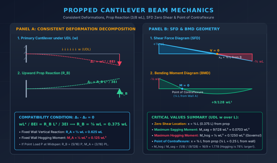
Case 1: Full Uniformly Distributed Load (ww over span LL)

  • Cantilever tip deflection under UDL: ΔB0=wL48EI\Delta_{B0} = \frac{wL^4}{8EI}
  • Prop Reaction: RB=wL4/8EIL3/3EI=38wL=0.375wL↑R_B = \frac{wL^4 / 8EI}{L^3 / 3EI} = \mathbf{\frac{3}{8} wL = 0.375 wL \uparrow}
  • Fixed Wall Reaction: RA=wL−RB=wL−38wL=58wL=0.625wL↑R_A = wL - R_B = wL - \frac{3}{8} wL = \mathbf{\frac{5}{8} wL = 0.625 wL \uparrow}
  • Fixed Wall Hogging Moment: MA=wL22−RBL=wL22−38wL2=18wL2=0.125wL2(Hogging)M_A = \frac{wL^2}{2} - R_B L = \frac{wL^2}{2} - \frac{3}{8} wL^2 = \mathbf{\frac{1}{8} wL^2 = 0.125 wL^2 \quad (\text{Hogging})}
  • Location of Zero Shear (V=0V = 0): Measuring xx from prop BB: V(x)=RB−wx=0  ⟹  x0=RBw=38L=0.375L(from Prop B)V(x) = R_B - wx = 0 \implies x_0 = \frac{R_B}{w} = \mathbf{\frac{3}{8} L = 0.375 L \quad (\text{from Prop } B)} (or 58L=0.625L\frac{5}{8} L = 0.625 L from fixed wall AA).
  • Maximum Sagging Bending Moment (Mmax⁡M_{\max}): Mmax⁡=RBx0−wx022=(38wL)(38L)−w2(38L)2=9128wL2≈0.0703wL2M_{\max} = R_B x_0 - \frac{w x_0^2}{2} = \left(\frac{3}{8} wL\right)\left(\frac{3}{8} L\right) - \frac{w}{2}\left(\frac{3}{8} L\right)^2 = \mathbf{\frac{9}{128} wL^2 \approx 0.0703 wL^2}
  • Moment Ratio: MhoggingMsagging=wL2/89wL2/128=169≈1.778\frac{M_{\text{hogging}}}{M_{\text{sagging}}} = \frac{wL^2 / 8}{9 wL^2 / 128} = \frac{16}{9} \approx \mathbf{1.778} The fixed-end hogging moment is 77.8%77.8\% larger than the maximum span sagging moment. Therefore, the cross-section design at the fixed wall governs!
  • Point of Contraflexure (M=0M = 0): M(x)=RBx−wx22=0  ⟹  x(38wL−wx2)=0  ⟹  xc=34L=0.75L(from Prop B)M(x) = R_B x - \frac{wx^2}{2} = 0 \implies x \left( \frac{3}{8} wL - \frac{wx}{2} \right) = 0 \implies x_c = \mathbf{\frac{3}{4} L = 0.75 L \quad (\text{from Prop } B)} (or 14L=0.25L\frac{1}{4} L = 0.25 L from fixed wall AA).
  • Point of Maximum Deflection: Integrating the elastic curve equation EId2ydx2=M(x)EI \frac{d^2y}{dx^2} = M(x) gives zero slope (dy/dx=0dy/dx = 0) at: xδ,max⁡=5−12L≈0.4215L(from Prop B)x_{\delta,\max} = \frac{\sqrt{5} - 1}{2} L \approx \mathbf{0.4215 L \quad (\text{from Prop } B)} Maximum downward deflection: δmax⁡=wL4185EI\delta_{\max} = \frac{wL^4}{185 EI}.

Case 2: Concentrated Point Load PP at Midspan (L/2L/2)

  • Cantilever tip deflection under midspan load PP: ΔB0=P(L/2)26EI(3L−L2)=PL224EI(5L2)=5PL348EI\Delta_{B0} = \frac{P (L/2)^2}{6EI} \left( 3L - \frac{L}{2} \right) = \frac{P L^2}{24 EI} \left( \frac{5L}{2} \right) = \frac{5 PL^3}{48 EI}
  • Prop Reaction: RB=5PL3/48EIL3/3EI=516P=0.3125P↑R_B = \frac{5 PL^3 / 48 EI}{L^3 / 3EI} = \mathbf{\frac{5}{16} P = 0.3125 P \uparrow}
  • Fixed Wall Reaction: RA=P−RB=1116P=0.6875P↑R_A = P - R_B = \mathbf{\frac{11}{16} P = 0.6875 P \uparrow}
  • Fixed Wall Hogging Moment: MA=P(L2)−RBL=PL2−516PL=316PL=0.1875PL(Hogging)M_A = P \left(\frac{L}{2}\right) - R_B L = \frac{PL}{2} - \frac{5}{16} PL = \mathbf{\frac{3}{16} PL = 0.1875 PL \quad (\text{Hogging})}
  • Sagging Moment under Load (x=L/2x = L/2 from BB): Mmid=RB(L2)=516P(L2)=532PL≈0.15625PLM_{\text{mid}} = R_B \left(\frac{L}{2}\right) = \frac{5}{16} P \left(\frac{L}{2}\right) = \mathbf{\frac{5}{32} PL \approx 0.15625 PL}
  • Point of Contraflexure: Measuring from fixed wall AA: M(x)=RAx−MA=0  ⟹  xc=MARA=3/16PL11/16P=311L≈0.2727L(from Wall A)M(x) = R_A x - M_A = 0 \implies x_c = \frac{M_A}{R_A} = \frac{3/16 PL}{11/16 P} = \mathbf{\frac{3}{11} L \approx 0.2727 L \quad (\text{from Wall } A)}.

2.3 Sinking / Settlement of Prop Support

If the simple prop at BB settles downward by an amount δ\delta under load:

ΔB0−RB⋅L33EI=δ  ⟹  RB=38wL−3EIδL3\Delta_{B0} - R_B \cdot \frac{L^3}{3EI} = \delta \implies \boxed{R_B = \frac{3}{8} wL - \frac{3EI\delta}{L^3}}
  • As settlement δ\delta increases, prop reaction RBR_B decreases, shedding load back to fixed wall AA.
  • Lift-Off Condition: The prop reaction drops to zero (RB=0R_B = 0) when the settlement equals the free cantilever tip deflection: δzero=wL48EI\delta_{\text{zero}} = \frac{wL^4}{8EI}

3. Fixed-Fixed Beams (Encastre Beams) (Ds=2D_s = 2)

A fixed-fixed beam has both ends rigidly clamped, preventing both translation and rotation (θA=θB=0,ΔA=ΔB=0\theta_A = \theta_B = 0, \Delta_A = \Delta_B = 0).

  • Total reactions in 2D flexure: RA,MA,RB,MBR_A, M_A, R_B, M_B (44 unknown reactions).
  • Static equilibrium equations: ∑Fy=0,∑M=0\sum F_y = 0, \sum M = 0 (22 equations).
  • Degree of Static Indeterminacy: Ds=4−2=2D_s = 4 - 2 = 2.
   Fixed A                                             Fixed B
   |=====================================================|
   |----------------------- Span L ----------------------|

3.1 Principle of Superposition & Moment-Area Formulation

The net bending moment M(x)M(x) at any section is the superposition of:

  1. Free Bending Moment Diagram (μ\mu-diagram): The bending moment of an imaginary simply supported beam of the same span carrying the identical external loads. (Always positive/sagging).
  2. Fixed End Moment Diagram (μ′\mu'-diagram): The bending moment diagram produced by the end fixity moments MAM_A and MBM_B. (Always negative/hogging).
M(x)=μ(x)−μ′(x)\boxed{M(x) = \mu(x) - \mu'(x)}

By Mohr's Moment-Area Theorems:

Because change in slope between fixed ends is zero (θB−θA=0\theta_B - \theta_A = 0):

  1. First Moment-Area Theorem (Equal Areas): Area of μ-diagram=Area of μ′-diagram  ⟹  Aμ=Aμ′\text{Area of } \mu\text{-diagram} = \text{Area of } \mu'\text{-diagram} \implies \boxed{A_{\mu} = A_{\mu'}}
  2. Second Moment-Area Theorem (Equal Centroids): The deviation of BB from the tangent at AA is zero (ΔB/A=0\Delta_{B/A} = 0): Aμ⋅xˉ=Aμ′⋅xˉ′\boxed{A_{\mu} \cdot \bar{x} = A_{\mu'} \cdot \bar{x}'}

3.2 Master Table of Fixed-End Moments (FEM)

Loading Condition Fixed End Moment MFABM_{FAB} (Left End) Fixed End Moment MFBAM_{FBA} (Right End) Center / Span Moment MspanM_{\text{span}}
Uniformly Distributed Load (ww over span LL) −wL212-\frac{wL^2}{12} +wL212+\frac{wL^2}{12} +wL224(at center)+\frac{wL^2}{24} \quad (\text{at center})
Central Point Load (PP at L/2L/2) −PL8-\frac{PL}{8} +PL8+\frac{PL}{8} +PL8(at center)+\frac{PL}{8} \quad (\text{at center})
Eccentric Point Load (PP at distances a,ba, b) −Pab2L2-\frac{P a b^2}{L^2} +Pa2bL2+\frac{P a^2 b}{L^2} +2Pa2b2L3(under load)+\frac{2 P a^2 b^2}{L^3} \quad (\text{under load})
UDL on Half Span (ww from AA to L/2L/2) −11wL2192-\frac{11 wL^2}{192} +5wL2192+\frac{5 wL^2}{192} +wL232+\frac{wL^2}{32}
Linearly Increasing Triangular Load (00 at AA to w0w_0 at BB) −w0L230-\frac{w_0 L^2}{30} +w0L220+\frac{w_0 L^2}{20} +w0L2243+\frac{w_0 L^2}{24\sqrt{3}}
Symmetrical Triangular Load (apex w0w_0 at midspan) −5w0L296-\frac{5 w_0 L^2}{96} +5w0L296+\frac{5 w_0 L^2}{96} +w0L232+\frac{w_0 L^2}{32}
Concentrated Couple (M0M_0 at distance aa from AA, bb from BB) +M0b(2a−b)L2+\frac{M_0 b (2a - b)}{L^2} +M0a(2b−a)L2+\frac{M_0 a (2b - a)}{L^2} -

(Note: In slope-deflection convention, clockwise end moments are positive; here, signs reflect standard clockwise/anticlockwise notations).


3.3 Key Structural Properties of Fixed Beams under UDL

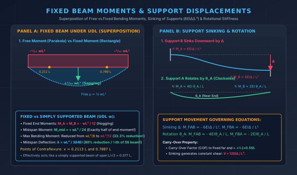
  1. Moments at Ends vs Center: Mends=wL212(Hogging),Mcenter=wL224(Sagging)M_{\text{ends}} = \frac{wL^2}{12} \quad (\text{Hogging}), \quad M_{\text{center}} = \frac{wL^2}{24} \quad (\text{Sagging}) Mends=2⋅McenterM_{\text{ends}} = 2 \cdot M_{\text{center}} The hogging moment at the supports is exactly twice the sagging moment at midspan!
  2. Points of Contraflexure: M(x)=wLx2−wx22−wL212=0  ⟹  x2−Lx+L26=0M(x) = \frac{wLx}{2} - \frac{wx^2}{2} - \frac{wL^2}{12} = 0 \implies x^2 - Lx + \frac{L^2}{6} = 0 xc=L±L2−4(L2/6)2=L2(1±13)x_c = \frac{L \pm \sqrt{L^2 - 4(L^2/6)}}{2} = \frac{L}{2} \left( 1 \pm \frac{1}{\sqrt{3}} \right) xc1=0.2113Landxc2=0.7887L\boxed{x_{c1} = 0.2113 L \quad \text{and} \quad x_{c2} = 0.7887 L} Distance between contraflexure points: Leff=L3≈0.577LL_{\text{eff}} = \frac{L}{\sqrt{3}} \approx 0.577 L. A fixed beam behaves dynamically like a simply supported beam of span 0.577L0.577 L suspended between two cantilevers of length 0.211L0.211 L.
  3. Midspan Deflection: δmid=wL4384EI=15(5wL4384EI)=0.20⋅δSS\boxed{\delta_{\text{mid}} = \frac{wL^4}{384 EI} = \frac{1}{5} \left( \frac{5wL^4}{384 EI} \right) = 0.20 \cdot \delta_{\text{SS}}}

4. Support Displacements in Fixed Beams

4.1 Sinking / Differential Settlement of One Support by Δ\Delta

When support BB settles downward by an amount Δ\Delta relative to support AA:

  • Both ends rotate relative to the chord, inducing counter-clockwise resisting fixed-end moments at both supports:
MFAB=MFBA=−6EIΔL2\boxed{M_{FAB} = M_{FBA} = -\frac{6EI\Delta}{L^2}}
  • Induced Vertical Shear Force: ∑MA=0  ⟹  V⋅L=MFAB+MFBA=12EIΔL2  ⟹  V=12EIΔL3\sum M_A = 0 \implies V \cdot L = M_{FAB} + M_{FBA} = \frac{12EI\Delta}{L^2} \implies \boxed{V = \frac{12EI\Delta}{L^3}} Upward vertical reaction at AA, downward vertical pull at BB.

4.2 Support Rotation by θA\theta_A

When support AA rotates clockwise by angle θA\theta_A while support BB remains rigidly fixed:

  • Near end moment (at AA): MFAB=−4EIθAL\boxed{M_{FAB} = -\frac{4EI\theta_A}{L}}
  • Far end moment (at BB): MFBA=−2EIθAL\boxed{M_{FBA} = -\frac{2EI\theta_A}{L}}
  • Carry-Over Factor (COF): COF=MFBAMFAB=2EIθ/L4EIθ/L=+12=+0.50\text{COF} = \frac{M_{FBA}}{M_{FAB}} = \frac{2EI\theta/L}{4EI\theta/L} = \mathbf{+\frac{1}{2} = +0.50} A moment applied at one fixed end induces half as much moment of the same sense at the opposite fixed end.

5. Engineering Visualizations

5.1 Propped Cantilever Beam Mechanics

Propped Cantilever Beam Mechanics

5.2 Fixed Beam Moments & Support Displacements

Fixed Beam Moments & Support Settlements

6. Solved Numerical Examples with Rigorous Calculations

Example 1: Comprehensive Propped Cantilever under Uniform Load

Problem Statement:

A propped cantilever beam ABAB of span L=6.0 mL = 6.0\text{ m} is rigidly clamped at support AA and supported on an unyielding simple roller prop at BB. The beam carries a uniformly distributed load of w=24.0 kN/mw = 24.0\text{ kN/m} over its entire length. The flexural rigidity is EI=40,000 kNm2EI = 40,000\text{ kNm}^2.

Determine:

  1. The vertical reaction RBR_B at the prop.
  2. The vertical reaction RAR_A and hogging moment MAM_A at fixed support AA.
  3. The location of the point of zero shear and the magnitude of maximum sagging bending moment.
  4. The location of the point of contraflexure.
  5. The net vertical deflection at midspan (x=3.0 mx = 3.0\text{ m}).
   Fixed Wall A                                        Prop B
   |=====================================================▲
   |↓↓↓↓↓↓↓↓↓↓↓↓↓↓↓↓↓↓↓↓↓↓↓↓↓↓↓↓↓↓↓↓↓↓↓↓↓↓↓↓↓↓↓↓↓↓↓↓↓↓↓↓↓| w = 24 kN/m
   |----------------------- L = 6.0 m -------------------|

Solution:

Step 1: Reactions and Fixed End Moment:

  • Upward prop reaction: RB=38wL=38(24.0 kN/m)(6.0 m)=54.000 kN↑R_B = \frac{3}{8} wL = \frac{3}{8}(24.0\text{ kN/m})(6.0\text{ m}) = \mathbf{54.000\text{ kN} \uparrow}
  • Wall vertical reaction: RA=58wL=58(24.0)(6.0)=90.000 kN↑R_A = \frac{5}{8} wL = \frac{5}{8}(24.0)(6.0) = \mathbf{90.000\text{ kN} \uparrow}
  • Check total vertical equilibrium: RA+RB=90+54=144 kN=wL=24×6=144 kN✓R_A + R_B = 90 + 54 = 144\text{ kN} = wL = 24 \times 6 = 144\text{ kN} \checkmark
  • Fixed wall hogging moment: MA=18wL2=18(24.0)(6.02)=108.000 kNm (Hogging)M_A = \frac{1}{8} wL^2 = \frac{1}{8}(24.0)(6.0^2) = \mathbf{108.000\text{ kNm \quad (Hogging)}}

Step 2: Shear Force and Maximum Sagging Moment:

  • Location of zero shear measured from prop BB: x0=RBw=54.0 kN24.0 kN/m=2.250 m (from Prop B)x_0 = \frac{R_B}{w} = \frac{54.0\text{ kN}}{24.0\text{ kN/m}} = \mathbf{2.250\text{ m \quad (from Prop } B)} (or 6.0−2.25=3.750 m6.0 - 2.25 = 3.750\text{ m} from wall AA).
  • Maximum sagging bending moment at x0=2.25 mx_0 = 2.25\text{ m}: Mmax⁡=RBx0−wx022=(54.0)(2.25)−24.0(2.252)2=121.50−60.75=+60.750 kNm (Sagging)M_{\max} = R_B x_0 - \frac{w x_0^2}{2} = (54.0)(2.25) - \frac{24.0(2.25^2)}{2} = 121.50 - 60.75 = \mathbf{+60.750\text{ kNm \quad (Sagging)}} Check analytical formula: Mmax⁡=9128wL2=9128(24.0)(36.0)=7776128=60.750 kNm✓M_{\max} = \frac{9}{128} wL^2 = \frac{9}{128}(24.0)(36.0) = \frac{7776}{128} = 60.750\text{ kNm} \checkmark

Step 3: Point of Contraflexure: Set bending moment to zero:

M(x)=RBx−wx22=0  ⟹  xc=2RBw=2(54.0)24.0=4.500 m (from Prop B)M(x) = R_B x - \frac{wx^2}{2} = 0 \implies x_c = \frac{2 R_B}{w} = \frac{2(54.0)}{24.0} = \mathbf{4.500\text{ m \quad (from Prop } B)}

Measured from fixed wall AA:

xc,A=6.0−4.500=1.500 m (from Wall A)(=14L)x_{c,A} = 6.0 - 4.500 = \mathbf{1.500\text{ m \quad (from Wall } A)} \quad \left( = \frac{1}{4} L \right)

Step 4: Net Midspan Deflection (x=3.0 mx = 3.0\text{ m} from wall AA): Using Macaulay's deflection equation for a cantilever under UDL with upward prop reaction RBR_B:

  • Downward deflection due to UDL on primary cantilever: yudl(x)=w24EI(x4−4Lx3+6L2x2)y_{\text{udl}}(x) = \frac{w}{24 EI} \left( x^4 - 4 L x^3 + 6 L^2 x^2 \right) For x=3.0 m,L=6.0 mx = 3.0\text{ m}, L = 6.0\text{ m}: x4=81,−4(6)(27)=−648,6(36)(9)=1944  ⟹  (81−648+1944)=1377x^4 = 81, \quad -4(6)(27) = -648, \quad 6(36)(9) = 1944 \implies (81 - 648 + 1944) = 1377 yudl(3)=24.0×137724×40,000=137740,000=0.034425 m=34.425 mm↓y_{\text{udl}}(3) = \frac{24.0 \times 1377}{24 \times 40,000} = \frac{1377}{40,000} = 0.034425\text{ m} = 34.425\text{ mm} \downarrow
  • Upward deflection due to prop reaction RB=54 kNR_B = 54\text{ kN}: yprop(x)=RB6EI(3Lx2−x3)y_{\text{prop}}(x) = \frac{R_B}{6 EI} \left( 3 L x^2 - x^3 \right) For x=3.0 mx = 3.0\text{ m}: 3(6)(9)−27=162−27=1353(6)(9) - 27 = 162 - 27 = 135 yprop(3)=54.0×1356×40,000=7290240,000=0.030375 m=30.375 mm↑y_{\text{prop}}(3) = \frac{54.0 \times 135}{6 \times 40,000} = \frac{7290}{240,000} = 0.030375\text{ m} = 30.375\text{ mm} \uparrow
  • Net downward midspan deflection: δmid=yudl−yprop=34.425−30.375=4.050 mm↓\delta_{\text{mid}} = y_{\text{udl}} - y_{\text{prop}} = 34.425 - 30.375 = \mathbf{4.050\text{ mm} \downarrow}

Example 2: Fixed-Fixed Beam with Eccentric Concentrated Load

Problem Statement:

A fixed-fixed beam ABAB of span L=8.0 mL = 8.0\text{ m} carries a single concentrated vertical point load P=60.0 kNP = 60.0\text{ kN} at a distance a=2.0 ma = 2.0\text{ m} from left fixed support AA (b=6.0 mb = 6.0\text{ m} from right fixed support BB).

Calculate:

  1. The fixed-end moments MFABM_{FAB} and MFBAM_{FBA}.
  2. The vertical support reactions RAR_A and RBR_B.
  3. The bending moment directly under the concentrated load.
  4. The locations of both points of contraflexure.
   Fixed A                   Load P = 60 kN                 Fixed B
   |=============|=============================================|
   |--- a = 2 m -|------------------ b = 6 m ------------------|
   |----------------------- Span L = 8.0 m --------------------|

Solution:

Step 1: Fixed-End Moments:

MFAB=Pab2L2=(60.0)(2.0)(6.02)8.02=60×2×3664=432064=67.500 kNm (Hogging)M_{FAB} = \frac{P a b^2}{L^2} = \frac{(60.0)(2.0)(6.0^2)}{8.0^2} = \frac{60 \times 2 \times 36}{64} = \frac{4320}{64} = \mathbf{67.500\text{ kNm \quad (Hogging)}} MFBA=Pa2bL2=(60.0)(2.02)(6.0)8.02=60×4×664=144064=22.500 kNm (Hogging)M_{FBA} = \frac{P a^2 b}{L^2} = \frac{(60.0)(2.0^2)(6.0)}{8.0^2} = \frac{60 \times 4 \times 6}{64} = \frac{1440}{64} = \mathbf{22.500\text{ kNm \quad (Hogging)}}

Step 2: Support Reactions: At support AA, the hogging restraint moment MFAB=67.500 kNmM_{FAB} = 67.500\text{ kNm} acts counterclockwise, whereas at support BB, the hogging restraint moment MFBA=22.500 kNmM_{FBA} = 22.500\text{ kNm} acts clockwise. Taking moments about AA (∑MA=0\sum M_A = 0, counterclockwise positive):

∑MA=0  ⟹  RB⋅L+MFAB−MFBA−P⋅a=0\sum M_A = 0 \implies R_B \cdot L + M_{FAB} - M_{FBA} - P \cdot a = 0 RB(8.0)+67.500−22.500−60.0(2.0)=0R_B(8.0) + 67.500 - 22.500 - 60.0(2.0) = 0 8.0RB+45.0−120.0=0  ⟹  8.0RB=75.0  ⟹  RB=9.375 kN↑8.0 R_B + 45.0 - 120.0 = 0 \implies 8.0 R_B = 75.0 \implies R_B = \mathbf{9.375\text{ kN} \uparrow} RA=P−RB=60.0−9.375=50.625 kN↑R_A = P - R_B = 60.0 - 9.375 = \mathbf{50.625\text{ kN} \uparrow}

(Direct formula check: RA=P(bL)2(1+2aL)=60(68)2(1+48)=60(0.5625)(1.5)=50.625 kNR_A = P\left(\frac{b}{L}\right)^2\left(1 + \frac{2a}{L}\right) = 60\left(\frac{6}{8}\right)^2\left(1 + \frac{4}{8}\right) = 60(0.5625)(1.5) = 50.625\text{ kN}; RB=P(aL)2(1+2bL)=60(0.0625)(2.5)=9.375 kNR_B = P\left(\frac{a}{L}\right)^2\left(1 + \frac{2b}{L}\right) = 60(0.0625)(2.5) = 9.375\text{ kN}).

Step 3: Bending Moment under the Load (x=2.0 mx = 2.0\text{ m}): From left support AA:

Mload=RA⋅a−MFAB=(50.625)(2.0)−67.500=101.250−67.500=+33.750 kNm (Sagging)M_{\text{load}} = R_A \cdot a - M_{FAB} = (50.625)(2.0) - 67.500 = 101.250 - 67.500 = \mathbf{+33.750\text{ kNm \quad (Sagging)}}

Independent check from right support BB (b=6.0 mb = 6.0\text{ m}):

Mload=RB⋅b−MFBA=(9.375)(6.0)−22.500=56.250−22.500=+33.750 kNm (Sagging)M_{\text{load}} = R_B \cdot b - M_{FBA} = (9.375)(6.0) - 22.500 = 56.250 - 22.500 = \mathbf{+33.750\text{ kNm \quad (Sagging)}}

Independent superposition check (μfree−Mfixed\mu_{\text{free}} - M_{\text{fixed}} at x=2.0 mx = 2.0\text{ m}):

μfree=PabL=60×2×68=90.000 kNm,Mfixed(2.0)=67.500−(67.500−22.5008.0)(2.0)=56.250 kNm\mu_{\text{free}} = \frac{P a b}{L} = \frac{60 \times 2 \times 6}{8} = 90.000\text{ kNm}, \quad M_{\text{fixed}}(2.0) = 67.500 - \left(\frac{67.500 - 22.500}{8.0}\right)(2.0) = 56.250\text{ kNm} Mload=90.000−56.250=+33.750 kNmM_{\text{load}} = 90.000 - 56.250 = \mathbf{+33.750\text{ kNm}}

Step 4: Points of Contraflexure:

  • In segment ACAC (0≤x≤2.0 m0 \le x \le 2.0\text{ m} from AA): M(x)=RAx−MFAB=0  ⟹  xc1=MFABRA=67.50050.625=1.333 m (from Support A)M(x) = R_A x - M_{FAB} = 0 \implies x_{c1} = \frac{M_{FAB}}{R_A} = \frac{67.500}{50.625} = \mathbf{1.333\text{ m \quad (from Support } A)}
  • In segment CBCB (0≤s≤6.0 m0 \le s \le 6.0\text{ m} from BB): M(s)=RBs−MFBA=0  ⟹  sc2=MFBARB=22.5009.375=2.400 m (from Support B)M(s) = R_B s - M_{FBA} = 0 \implies s_{c2} = \frac{M_{FBA}}{R_B} = \frac{22.500}{9.375} = \mathbf{2.400\text{ m \quad (from Support } B)} (or 8.000−2.400=5.600 m8.000 - 2.400 = \mathbf{5.600\text{ m}} from support AA).

Example 3: Fixed Beam under Uniform Load with Support Sinking

Problem Statement:

A fixed-fixed beam ABAB of span L=6.0 mL = 6.0\text{ m} and flexural rigidity EI=30,000 kNm2EI = 30,000\text{ kNm}^2 carries a uniformly distributed load of w=20.0 kN/mw = 20.0\text{ kN/m}. During service, support BB sinks vertically downward by Δ=10.0 mm=0.010 m\Delta = 10.0\text{ mm} = 0.010\text{ m}.

Calculate the net final fixed-end moments and reactions at both supports, and determine the percentage change in moment at support AA.

Solution:

Step 1: Gravity Load Fixed-End Moments: Under UDL w=20 kN/mw = 20\text{ kN/m}:

Mudl=wL212=20.0×6.0212=72012=60.000 kNmM_{\text{udl}} = \frac{wL^2}{12} = \frac{20.0 \times 6.0^2}{12} = \frac{720}{12} = 60.000\text{ kNm}
  • At AA: MFAB,udl=−60.000 kNmM_{FAB, \text{udl}} = -60.000\text{ kNm} (Hogging / counter-clockwise)
  • At BB: MFBA,udl=+60.000 kNmM_{FBA, \text{udl}} = +60.000\text{ kNm} (Hogging / clockwise)

Step 2: Settlement Fixed-End Moments: When support BB sinks downward relative to AA, both ends develop counter-clockwise restraining moments:

Msink=6EIΔL2=6(30,000 kNm2)(0.010 m)6.02=180036=50.000 kNmM_{\text{sink}} = \frac{6EI\Delta}{L^2} = \frac{6(30,000\text{ kNm}^2)(0.010\text{ m})}{6.0^2} = \frac{1800}{36} = \mathbf{50.000\text{ kNm}}
  • At AA: MFAB,sink=−50.000 kNmM_{FAB, \text{sink}} = -50.000\text{ kNm} (counter-clockwise)
  • At BB: MFBA,sink=−50.000 kNmM_{FBA, \text{sink}} = -50.000\text{ kNm} (counter-clockwise)

Step 3: Superposition of Net Fixed-End Moments:

  • Net Moment at Support AA: MFAB,net=−60.000−50.000=−110.000 kNm (Hogging)M_{FAB, \text{net}} = -60.000 - 50.000 = \mathbf{-110.000\text{ kNm \quad (Hogging)}}
  • Net Moment at Support BB: MFBA,net=+60.000−50.000=+10.000 kNm (Hogging reduced to near zero)M_{FBA, \text{net}} = +60.000 - 50.000 = \mathbf{+10.000\text{ kNm \quad (Hogging reduced to near zero)}}

Critical Engineering Observation: Settlement of support BB increases the hogging moment at support AA from 60 kNm60\text{ kNm} to 110 kNm110\text{ kNm}—a +83.33%+83.33\% increase! Meanwhile, hogging at settling support BB is almost completely relieved (drops by 83.3%83.3\%).

Step 4: Net Vertical Support Reactions:

  • Gravity load reactions: RA,udl=RB,udl=wL2=20×62=60.000 kNR_{A, \text{udl}} = R_{B, \text{udl}} = \frac{wL}{2} = \frac{20 \times 6}{2} = 60.000\text{ kN}.
  • Couple due to settlement moments: Vsink=MFAB,sink+MFBA,sinkL=50+506.0=1006=16.667 kNV_{\text{sink}} = \frac{M_{FAB, \text{sink}} + M_{FBA, \text{sink}}}{L} = \frac{50 + 50}{6.0} = \frac{100}{6} = 16.667\text{ kN} (Upward at AA, downward at BB).
  • Net Reactions: RA=60.000+16.667=76.667 kN↑R_A = 60.000 + 16.667 = \mathbf{76.667\text{ kN} \uparrow} RB=60.000−16.667=43.333 kN↑R_B = 60.000 - 16.667 = \mathbf{43.333\text{ kN} \uparrow} Check equilibrium: RA+RB=76.667+43.333=120.000 kN=wL✓R_A + R_B = 76.667 + 43.333 = 120.000\text{ kN} = wL \checkmark.

7. Common Pitfalls, Exam Traps & Misconceptions

7.1 Location of Contraflexure: Measured from Prop vs Fixed Wall

  • Trap: Remembering x=34Lx = \frac{3}{4} L and measuring it from the fixed wall.
  • Rule: In a propped cantilever under UDL:
    • xc=34L=0.75Lx_c = \frac{3}{4} L = \mathbf{0.75 L} measured from the simple prop BB.
    • xc=14L=0.25Lx_c = \frac{1}{4} L = \mathbf{0.25 L} measured from the fixed wall AA.

7.2 Point of Maximum Deflection vs Point of Zero Shear

  • Trap: Assuming that maximum deflection occurs at the point of maximum sagging moment (x=0.375Lx = 0.375 L from prop).
  • Rule: Zero shear marks the maximum bending moment, not maximum deflection. In a propped cantilever under UDL, maximum downward deflection occurs where slope θ=0\theta = 0, which is at x≈0.4215Lx \approx \mathbf{0.4215 L} from the prop.

7.3 Support Settlement Signs in Fixed Beams

  • Trap: Giving opposite signs to settlement moments at supports AA and BB.
  • Rule: When the right support sinks downward, the chord rotates clockwise. To resist this clockwise chord rotation, both supports develop counter-clockwise moments: MFAB=MFBA=−6EIΔL2M_{FAB} = M_{FBA} = -\frac{6EI\Delta}{L^2} Both moments have the same algebraic sense and add to the hogging moment at the non-settling support while relieving the settling support.

8. Codal Provisions & Master Formula Sheet

8.1 IS 456:2000 Moment Redistribution Provisions (Clause 37.1)

In reinforced concrete continuous and fixed beams, elastic fixed-end moments calculated by elastic theory may be redistributed by up to 30%30\%, provided that:

  1. Static equilibrium between internal and external forces is maintained.
  2. The neutral axis depth factor satisfies: xud≤(βb−0.4)whereβb=MredistributedMelastic\frac{x_u}{d} \le \left( \beta_b - 0.4 \right) \quad \text{where} \quad \beta_b = \frac{M_{\text{redistributed}}}{M_{\text{elastic}}}

8.2 Master Formula Sheet

Structural System & ParameterExact FormulaPropped Cantilever (UDL): Prop Reaction RBRB=38wL=0.375wLPropped Cantilever (UDL): Wall Reaction RARA=58wL=0.625wLPropped Cantilever (UDL): Wall Moment MAMA=18wL2=0.125wL2Propped Cantilever (UDL): Zero Shear Pointx0=38L from prop BPropped Cantilever (UDL): Max Sagging MomentMmax⁡=9128wL2≈0.0703wL2Propped Cantilever (UDL): Point of Contraflexurexc=34L from prop B(0.25L from wall)Propped Cantilever (Midspan Load P): Prop RBRB=516P,MA=316PLFixed Beam (UDL): Fixed End MomentMFAB=−wL212,MFBA=+wL212Fixed Beam (UDL): Center Sagging MomentMcenter=+wL224=12MendsFixed Beam (UDL): Contraflexure Pointsxc=L2(1±13)=0.2113L,0.7887LFixed Beam (UDL): Center Deflectionδmid=wL4384EI=15δSSFixed Beam (Eccentric Load P): End MomentsMFAB=−Pab2L2,MFBA=+Pa2bL2Fixed Beam Support Sinking ΔMFAB=MFBA=−6EIΔL2,V=12EIΔL3Fixed Beam Support Rotation θAMFAB=−4EIθAL,MFBA=−2EIθAL\begin{array}{|l|l|} \hline \textbf{Structural System \& Parameter} & \textbf{Exact Formula} \\ \hline \text{Propped Cantilever (UDL): Prop Reaction } R_B & R_B = \frac{3}{8} wL = 0.375 wL \\ \hline \text{Propped Cantilever (UDL): Wall Reaction } R_A & R_A = \frac{5}{8} wL = 0.625 wL \\ \hline \text{Propped Cantilever (UDL): Wall Moment } M_A & M_A = \frac{1}{8} wL^2 = 0.125 wL^2 \\ \hline \text{Propped Cantilever (UDL): Zero Shear Point} & x_0 = \frac{3}{8} L\text{ from prop } B \\ \hline \text{Propped Cantilever (UDL): Max Sagging Moment} & M_{\max} = \frac{9}{128} wL^2 \approx 0.0703 wL^2 \\ \hline \text{Propped Cantilever (UDL): Point of Contraflexure} & x_c = \frac{3}{4} L\text{ from prop } B \quad (0.25 L\text{ from wall}) \\ \hline \text{Propped Cantilever (Midspan Load } P\text{): Prop } R_B & R_B = \frac{5}{16} P, \quad M_A = \frac{3}{16} PL \\ \hline \text{Fixed Beam (UDL): Fixed End Moment} & M_{FAB} = - \frac{wL^2}{12}, \quad M_{FBA} = + \frac{wL^2}{12} \\ \hline \text{Fixed Beam (UDL): Center Sagging Moment} & M_{\text{center}} = + \frac{wL^2}{24} = \frac{1}{2} M_{\text{ends}} \\ \hline \text{Fixed Beam (UDL): Contraflexure Points} & x_c = \frac{L}{2} \left(1 \pm \frac{1}{\sqrt{3}}\right) = 0.2113 L, \quad 0.7887 L \\ \hline \text{Fixed Beam (UDL): Center Deflection} & \delta_{\text{mid}} = \frac{wL^4}{384 EI} = \frac{1}{5} \delta_{\text{SS}} \\ \hline \text{Fixed Beam (Eccentric Load } P\text{): End Moments} & M_{FAB} = - \frac{P a b^2}{L^2}, \quad M_{FBA} = + \frac{P a^2 b}{L^2} \\ \hline \text{Fixed Beam Support Sinking } \Delta & M_{FAB} = M_{FBA} = - \frac{6EI\Delta}{L^2}, \quad V = \frac{12EI\Delta}{L^3} \\ \hline \text{Fixed Beam Support Rotation } \theta_A & M_{FAB} = - \frac{4EI\theta_A}{L}, \quad M_{FBA} = - \frac{2EI\theta_A}{L} \\ \hline \end{array}