End Block Design & Transmission Length (IS 1343:2012)
In this chapter (4 topics)
On this page
- 1. Topic Title and Metadata
- 2. Prerequisites and Engineering Context
- 3. Fundamental Physical and Engineering Principles
- 3.1 Pre-Tensioning Transfer: The Transmission Zone & The Hoyer Effect
- 3.2 Transmission Length (Lt) vs Development Length (Ld)
- 3.3 Post-Tensioning: The Anchorage Zone (End Block) Mechanics
- 4. Rigorous Mathematical Derivations & Code Formulations
- 4.1 Transmission Length Formulations (IS 1343:2012 Cl. 19.6.2)
- 4.2 Anchorage Zone Bearing Stress Verification (IS 1343:2012 Cl. 19.6.3.1)
- 4.3 Bursting Tensile Force Formulations
- 4.4 Design of Transverse Bursting Reinforcement
- 5. Detailing Rules and Codal Mandates
- 6. SVG Diagrams and Visual Explanations
- 6.1 Anchorage Zone Stress Trajectories & Bursting Tension
- 6.2 Pre-Tensioning Transmission Mechanics & End Block Detailing
- 7. Solved Numerical Examples
- 7.1 Example 1: Transmission Length & Bond Stress in a Pre-Tensioned Railway Sleeper
- 7.2 Example 2: End Block Design for a Post-Tensioned Beam (IS 1343:2012)
- 7.3 Example 3: Multiple Anchorages by Guyon's Method of Symmetric Prisms
- 8. Common Pitfalls, Misconceptions, and Examination Traps
- 9. Comparative Analysis and Summary Tables
- 9.1 Pre-Tensioning Transfer vs Post-Tensioning Anchorage
- 9.2 Comparison of Anchorage Zone Analysis Methods
- 10. Exam-Specific Focus and Formula Cheat Sheet
- 10.1 Must-Remember Formulas for Quick Calculations
- 10.2 Exam Weightage Summary
- 11. Practice Problems and Self-Assessment with Numerical Answers
- 12. Standard References and Further Reading
1. Topic Title and Metadata
| Attribute | Specification |
|---|---|
| Topic ID | RCC-10-04 |
| Module / Subject | Subject 05: Reinforced Concrete Structures (RCC) & Prestressed Concrete |
| Chapter | Chapter 10: Prestressed Concrete (IS 1343:2012) |
| Topic Title | End Block Design, Anchorage Zone Stresses & Transmission Length |
| Applicable Standards | IS 1343:2012 (Prestressed Concrete — Code of Practice), IS 456:2000, IRC:112-2020, BS EN 1992-1-1 |
| Target Examinations | GATE CE, UPSC ESE (Paper-I), SSC JE, State PSC AE/JE, RRB JE |
| Primary Authorship | Civil Engineering Autonomous Master Repository |
| Verification Gate | Level 1 through Level 7 (Mathematical Recalculation, Codal Compliance, SVG Validation) |
2. Prerequisites and Engineering Context
Prior to mastering anchorage zone mechanics and transmission length, students and structural engineers must be thoroughly conversant with:
- Prestress Losses & Transfer Dynamics (
RCC-10-02): Distinction between immediate losses (elastic shortening, anchorage slip, friction) and time-dependent losses (creep, shrinkage, relaxation). - Beam Stress Analysis (
RCC-10-03): Saint-Venant's principle, stress concept (), and internal couple mechanics. - Bond and Development Length in Concrete (
RCC-03-03): Shear-bond slip, mechanical interlock, adhesive grip, and confinement dilation. - Theory of Elasticity: Two-dimensional stress distributions, concentrated line and patch loads on a semi-infinite elastic prism (Boussinesq and Flamant problem), Airy stress functions, and isochromatic fringe patterns.
In prestressed concrete design, the transfer of immense concentrated prestressing forces (often exceeding several thousands of kilonewtons) into the concrete body represents one of the most structurally critical zones. In pre-tensioned members, transfer occurs gradually along a specific embedment distance termed the transmission length via interfacial bond, shear stress, and radial wedge dilation (the Hoyer effect). In post-tensioned members, the tendon force is introduced suddenly through discrete steel bearing plates, creating intense transverse tensile stresses—known as bursting stresses and spalling stresses—that can split the end block longitudinally if adequate reinforcement is not detailed.
3. Fundamental Physical and Engineering Principles
3.1 Pre-Tensioning Transfer: The Transmission Zone & The Hoyer Effect
In pre-tensioned prestressed concrete (such as railway sleepers, hollow-core slabs, and precast bridge girders), there are no mechanical anchor plates or bearing wedges permanently left at the beam ends. The prestress is transferred to the concrete exclusively through interfacial bond over a finite zone at each end of the member:
[ Free End ] <----------- Transmission Length (Lt) -----------> [ Fully Prestressed Zone ]
Steel Stress = 0                                                Steel Stress = f_pe
Bond Stress peaks                                               Bond Stress decays to 0
The mechanism of bond transfer comprises three distinct physical components:
- Adhesion: Chemical and microscopic physical adherence between the cement paste matrix and the steel wire surface. This is destroyed at very low stress levels upon tendon release.
- Mechanical Interlock / Indentation Grip: For twisted multi-wire strands (7-wire strands) or indented/crimped wires, the concrete forms matching ridges that mechanically prevent longitudinal slipping.
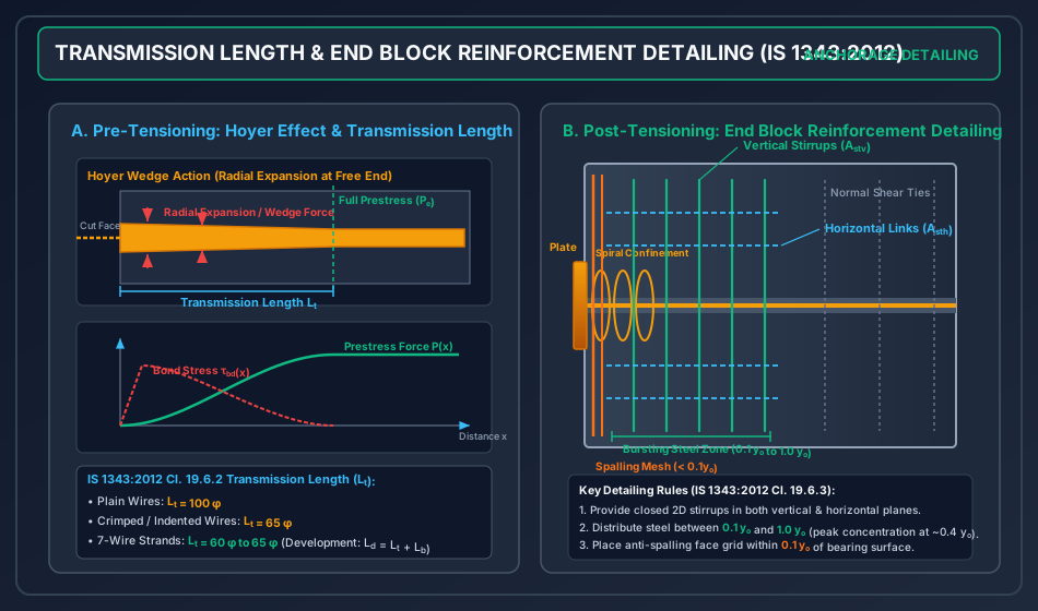
- The Hoyer Effect (Wedge Action):
- When a tendon is tensioned in the pre-tensioning bed prior to casting, its axial tensile strain causes a lateral Poisson contraction (where is Poisson's ratio of steel).
- After the concrete hardens and the tendon is severed at the abutment, the tendon at the extreme free end contracts axially, relaxing its axial tension to zero.
- Consequently, Poisson's contraction is released at the free end, causing the tendon to expand radially ().
- The surrounding hardened concrete matrix strongly resists this radial expansion, generating heavy radial compressive contact pressures across the interface.
- By Coulomb friction, this intense radial pressure mobilizes high frictional shear capacity . The tendon acts like a wedge driven into the concrete, locking the tendon securely and transferring force within a relatively short embedment distance.
       [Surrounding Concrete Matrix]
               ↓↓↓↓ p_r (Radial Pressure)
  ========================================== Tendon (Severed End)
  <-- Wedge Action / Radial Expansion (Hoyer)
  ========================================== Tendon
               ↑↑↑↑ p_r (Radial Pressure)
       [Surrounding Concrete Matrix]
3.2 Transmission Length () vs Development Length ()
A crucial distinction tested in GATE and ESE:
- Transmission Length (): The embedment distance measured from the member's free end required to build up the effective prestress force from zero to its full design effective value under service conditions.
- Flexural Bond Length (): The additional embedment length required beyond to develop the ultimate tensile strength of the tendon when the beam is subjected to its ultimate design bending moment at flexural failure.
- Development Length (): The total embedment length required from the free end to the critical section carrying the ultimate moment capacity:
3.3 Post-Tensioning: The Anchorage Zone (End Block) Mechanics
In post-tensioned beams, tendons are anchored against the end face via heavy steel bearing plates (e.g., Freyssinet cones, VSL wedges, Magnel sandwich plates).
3.3.1 Saint-Venant's Principle & Lead-in Distance
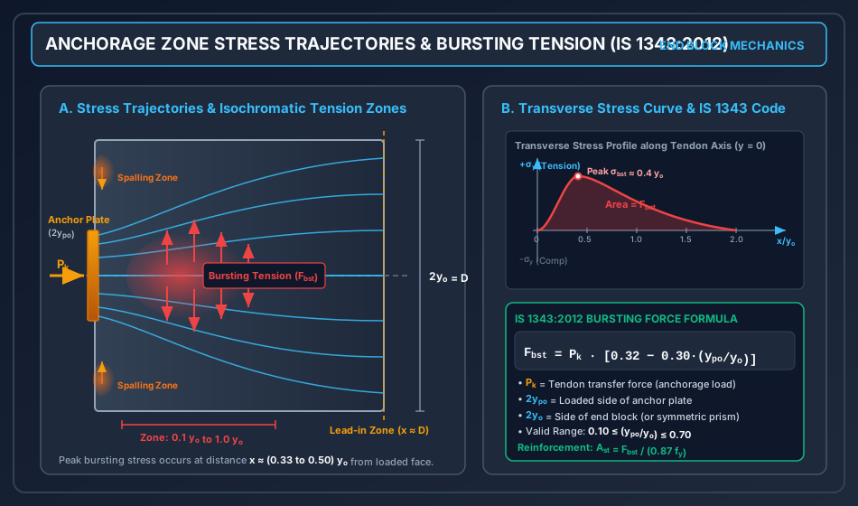
Immediately under the bearing plate, the stress distribution is highly localized and non-linear. According to Saint-Venant's Principle, the localized perturbation in the stress field dissipates and transforms into the classical linear bending stress distribution () at a longitudinal distance from the loaded face approximately equal to the depth of the section (). This transitional zone of length is defined as the End Block or Anchorage Zone.
3.3.2 Principal Stress Trajectories in the End Block
When a concentrated jacking force is applied to an anchor plate of depth on a section of total depth :
- The compressive stress trajectories diverge outward (fan out) from the concentrated plate area toward the full cross-sectional boundaries.
- The divergence (convex curvature) of compressive stress trajectories inevitably induces transverse tensile stresses () perpendicular to the tendon axis to maintain internal equilibrium.
- Bursting Tension Zone: Along the longitudinal centroidal axis of the tendon, the transverse stress changes from zero (or slight compression) right beneath the plate to a maximum transverse tensile stress at a distance of approximately . It then gradually decays to zero at . Integrating these tensile stresses yields the Total Bursting Tensile Force ().
- Spalling Tension Zone: At the end face itself, near the unloaded outer corners and between adjacent anchorages, deformation compatibility creates concave curvature in the face, causing high transverse tensile stresses termed spalling stresses. If unreinforced, spalling produces face cracking along the bearing plate perimeter.
4. Rigorous Mathematical Derivations & Code Formulations
4.1 Transmission Length Formulations (IS 1343:2012 Cl. 19.6.2)
IS 1343:2012 specifies the design transmission length as a direct multiple of the nominal tendon diameter :
| Tendon Type | Codal Factor | Transmission Length |
|---|---|---|
| Plain High-Tensile Wire | ||
| Crimped or Indented Wire | ||
| 7-Wire Strand (Normal / Compacted) |
Factors Affecting Transmission Length:
- Tendon Diameter (): . Smaller diameter wires develop shorter transmission lengths because their surface-area-to-cross-sectional-area ratio () is much higher.
- Surface Deformation: Crimping, indentation, or helical twisting (strands) increases mechanical grip, slashing by compared to smooth plain wires.
- Concrete Transfer Strength (): Higher increases concrete shear modulus and tensile bursting resistance, reducing .
- Method of Release: Gradual release via hydraulic de-jacking jacks produces smooth stress build-up. Sudden flame cutting or sawing causes shock waves, wire slip, and increases by .
4.2 Anchorage Zone Bearing Stress Verification (IS 1343:2012 Cl. 19.6.3.1)
The direct compressive stress in the concrete immediately beneath the anchorage plate must not exceed the permissible bearing stress to prevent localized crushing. The permissible bearing stress under working or ultimate loads is governed by the confinement ratio:
where:
- is the characteristic cube compressive strength of concrete at the time of prestress transfer.
- is the gross net bearing area of the anchor plate ().
- is the largest area of the supporting surface that is geometrically similar to and concentric with the bearing plate.
- The confinement enhancement factor is capped at a maximum value of , meaning that under ideal triaxial confinement, (clamped to codal limits).
4.3 Bursting Tensile Force Formulations
4.3.1 Guyon's Symmetrical Prism Theory
Yves Guyon developed the widely adopted Method of Symmetrical Prisms for solving anchorage problems:
- When an anchorage force acts eccentrically at a distance from the beam centroid, the depth of the symmetrical prism is taken as twice the distance from the center of the anchor plate to the nearest outer concrete boundary:
- Within this fictitious symmetrical prism of depth , the eccentric load acts symmetrically (centrally).
- Guyon derived the maximum transverse tensile stress along the axis:
- The bursting force is the integral of the transverse tensile stress over the tensile zone ().
4.3.2 Magnel's Theoretical Formulation
Gustave Magnel modeled the end block as a semi-infinite beam on an elastic foundation, expressing the transverse stress as a cubic polynomial satisfying boundary equilibrium:
where is the fictitious shearing moment. Magnel showed that peak bursting tension occurs at and spalling occurs directly on the loaded face.
4.3.3 IS 1343:2012 Codal Empirical Formula (Cl. 19.6.3.2)
IS 1343 adopts an empirical formulation derived from extensive photoelastic experiments and finite element analyses for calculating the total bursting tensile force :
where:
- = Tendon jacking force at transfer (characteristic anchorage load in kN or N).
- = Side dimension of the anchorage plate in the direction considered (vertical or horizontal).
- = Side dimension of the symmetrical prism or end block in the direction considered.
- = Plate-to-prism dimension ratio (valid for ).
- = Total transverse tensile bursting force acting across the axis.
      Ratio (y_po / y_o)   |   Bursting Force Ratio (F_bst / P_k)
      -------------------------------------------------------
             0.10          |   0.32 - 0.30(0.10) = 0.290  (29.0% of P_k)
             0.20          |   0.32 - 0.30(0.20) = 0.260  (26.0% of P_k)
             0.30          |   0.32 - 0.30(0.30) = 0.230  (23.0% of P_k)
             0.40          |   0.32 - 0.30(0.40) = 0.200  (20.0% of P_k)
             0.50          |   0.32 - 0.30(0.50) = 0.170  (17.0% of P_k)
             0.60          |   0.32 - 0.30(0.60) = 0.140  (14.0% of P_k)
             0.70          |   0.32 - 0.30(0.70) = 0.110  (11.0% of P_k)
Key Insight: As the bearing plate size increases relative to the end block (), the load becomes more uniformly distributed at the face, and the bursting tension rapidly drops toward zero. Conversely, highly concentrated point anchors () induce massive bursting forces approaching nearly of the prestressing load.
4.4 Design of Transverse Bursting Reinforcement
Because the tensile strength of concrete is neglected in the anchorage zone under limit states, the entire bursting tensile force must be carried by steel reinforcement:
where:
- for Limit State Design (with commonly used to prevent excessive tensile strain and cracking, or if strict crack-width control is enforced).
- Spatial Distribution: This reinforcement must be provided in the form of a closed orthogonal 2D cage (closed stirrups in both vertical and horizontal planes) distributed over a longitudinal length extending from to measured from the loaded end face.
- To match the stress curve, the highest intensity of stirrups should be concentrated between and .
5. Detailing Rules and Codal Mandates
- Orthogonal Reinforcement: Concrete in the end block undergoes bursting tension in both orthogonal planes (vertical and horizontal). Therefore, reinforcement must be provided in both directions:
- Vertical closed stirrups of area to resist vertical bursting.
- Horizontal closed links of area to resist lateral/horizontal bursting.
- Anti-Spalling Reinforcement: Near the loaded end face (within distance ), heavy localized tensile stresses exist. A welded wire mesh or fine link cage must be placed within of the end face to prevent corner spalling and surface flaking.
- Confinement Behind Bearing Plates: To develop high permissible bearing stress , a cylindrical spiral or multiple layers of orthogonal grid mats must be wrapped tightly around the tendon duct immediately behind the bearing plate.
- Multiple Anchorage Detailing: When multiple anchors are placed on the end block:
- Check Local Bursting using Guyon's symmetrical prism for each individual anchor.
- Check Global Bursting considering the entire group of anchors as a single equivalent concentrated resultant load acting on the overall beam section.
- Detail the larger of the two reinforcement requirements.
6. SVG Diagrams and Visual Explanations
6.1 Anchorage Zone Stress Trajectories & Bursting Tension
The following original diagram illustrates the flow of compressive stress trajectories, the formation of the transverse bursting isochromatics along the axis, the corner spalling zones, and the corresponding mathematical curve of transverse stress .
6.2 Pre-Tensioning Transmission Mechanics & End Block Detailing
The following diagram contrasts pre-tensioned transmission length () and the Hoyer wedge effect with post-tensioned 3D end block reinforcement detailing (stirrup cages, spalling mesh, and confinement spirals).
7. Solved Numerical Examples
7.1 Example 1: Transmission Length & Bond Stress in a Pre-Tensioned Railway Sleeper
Problem Statement:
A pre-tensioned concrete railway sleeper is manufactured using 7-wire high-tensile steel strands of nominal diameter . At transfer, the effective prestressing force per strand after immediate elastic shortening is . Concrete grade at transfer is M35 ().
- Determine the design transmission length as per IS 1343:2012 provisions. Compare this with plain wire and crimped wire of the same diameter.
- Calculate the average interfacial bond stress mobilized over the transmission length based on nominal strand perimeter .
- Calculate the average bond stress considering the outer perimeter of a 7-wire strand .
Step-by-Step Solution:
-
Step 1: Codal Transmission Lengths (IS 1343:2012 Cl. 19.6.2)
- For plain wires:
- For crimped / indented wires:
- For 7-wire strands (IS 1343 standard):
-
Step 2: Average Bond Stress with Nominal Perimeter
- Nominal circumference:
- From force equilibrium over embedment length :
-
Step 3: Average Bond Stress with Actual 7-Wire Strand Outer Perimeter
- For a 7-wire strand consisting of 6 outer wires wrapped helically around a central king wire, the exposed outer perimeter is approximately :
- Actual mobilized average bond stress:
7.2 Example 2: End Block Design for a Post-Tensioned Beam (IS 1343:2012)
Problem Statement:
The end block of a post-tensioned prestressed concrete beam has a width and overall depth . A single central anchorage plate of depth and width transmits a tendon transfer jacking force . The yield strength of transverse reinforcement is . Concrete transfer strength is .
- Verify the bearing stress under the anchorage plate.
- Calculate the bursting tensile force in both the vertical and horizontal planes as per IS 1343:2012.
- Design the required vertical and horizontal transverse reinforcement ( and ) and specify their distribution zone.
Step-by-Step Solution:
-
Step 1: Anchorage Plate Bearing Stress Check
- Bearing area .
- Applied bearing stress:
- Maximum concentric geometrically similar area : The section is (aspect ratio , matching the plate ratio ). Let available width = , matching height = .
- Permissible bearing stress (IS 1343 Cl. 19.6.3.1):
Clamped to .
Observation: Applied slightly exceeds ; provide heavy confinement spirals behind the plate to safely permit the load.
-
Step 2: Bursting Tensile Force Calculation
-
Vertical Direction:
Using IS 1343:2012 Cl. 19.6.3.2:
-
Horizontal Direction:
-
-
Step 3: Transverse Steel Design & Distribution
- Permissible design tensile stress in steel:
- Vertical steel area: Provide 2-legged closed stirrups ():
- Horizontal steel area: Provide 2-legged horizontal links ():
- Distribution Zone: Between and from the loaded end face: Distribute the 5 vertical stirrups and 4 horizontal links uniformly over the zone (spacing ).
7.3 Example 3: Multiple Anchorages by Guyon's Method of Symmetric Prisms
Problem Statement:
A post-tensioned concrete girder has an overall depth and width . Prestress is applied through two identical anchorage plates symmetrically located at from the top and bottom faces, respectively (each transmitting ). Each anchor plate measures (). Use .
- Calculate the overall global bursting tensile force for the combined system.
- Formulate Guyon's symmetric prisms for the individual anchorages and calculate the local bursting tensile force for each anchor.
- Compare local vs global reinforcement requirements and specify the governing design.
Step-by-Step Solution:
-
Step 1: Global Bursting Analysis
- Total prestressing force: .
- Overall depth: .
- Overall loaded depth covering both anchors: Distance between centers = . Total out-to-out plate depth: .
- Global bursting force (IS 1343 formula):
-
Step 2: Local Bursting Analysis via Guyon's Symmetrical Prisms
- For the upper anchor (): Center is located at distance from top boundary. The height of Guyon's symmetrical prism is twice the distance to the nearest boundary: Plate depth: .
- Local bursting force per prism:
- Total local bursting force for both prisms:
-
Step 3: Comparison and Governing Design
- Notice that .
- As per Guyon's principle and IS 1343:2012, local bursting governs the design within each individual prism zone.
- Steel area required per prism zone:
- Detail of vertical stirrups within the upper prism zone () and another within the lower prism zone.
- In addition, provide nominal anti-spalling mesh across the unloaded middle zone between the two plates to arrest tensile splitting.
8. Common Pitfalls, Misconceptions, and Examination Traps
- Confusing Transmission Length with Development Length:
- Trap: Believing that prestress transfer and ultimate flexural resistance happen over the same length.
- Reality: is for developing service prestress under elastic bond. is much longer, ensuring tendon yield without bond slip at ultimate flexural failure.
- Assuming Zero Bursting Tension for Uniform Compression:
- Trap: Thinking that because is purely compressive, no tension exists in the end block.
- Reality: Spreading of compressive force vectors inherently produces transverse tensile stresses () perpendicular to the load path.
- Applying Full Beam Depth for Eccentric Tendons:
- Trap: Taking when the tendon has an eccentricity .
- Reality: Under Guyon's method, . Taking full overestimates , underestimates , and results in an incorrect, unconservative bursting force.
- Neglecting Horizontal Bursting Tension:
- Trap: Designing reinforcement only in the vertical direction.
- Reality: The concentrated jacking force expands in three dimensions. Horizontal bursting tension is equally dangerous and can split the beam webs laterally.
- Placing Stirrups Too Far from the Jacking Face:
- Trap: Distributing bursting stirrups uniformly over the entire span.
- Reality: Bursting tension vanishes beyond . Placing stirrups beyond renders them completely ineffective against end block splitting.
9. Comparative Analysis and Summary Tables
9.1 Pre-Tensioning Transfer vs Post-Tensioning Anchorage
| Feature | Pre-Tensioned Transfer Zone | Post-Tensioned Anchorage Zone (End Block) |
|---|---|---|
| Transfer Mechanism | Bond, friction, and Hoyer wedge effect | Direct bearing plates and mechanical wedge grips |
| Zone Length | Transmission length | Lead-in distance (depth of beam) |
| Tendon Stress at End Face | Zero (builds up to at ) | Full jacking stress |
| Primary Risk | Bond slip, strand pull-in | Longitudinal splitting, concrete bearing crushing |
| Reinforcement Required | Nominal end ties, confinement loops | Heavy 2D orthogonal closed stirrup cage & face mesh |
9.2 Comparison of Anchorage Zone Analysis Methods
| Method | Approach / Basis | Strengths | Limitations |
|---|---|---|---|
| Guyon's Method | Symmetrical prism & photoelasticity | Excellent for eccentric & multiple tendons | Slightly conservative for deep beams |
| Magnel's Method | Higher-order polynomial stress functions | Detailed stress distribution along beam | Complex algebra, less intuitive |
| IS 1343:2012 Empirical | Linearized fit | Fast, reliable, codified for competitive exams | Valid only for |
| Strut-and-Tie Model (STM) | Truss analogy (Eurocode 2 / ACI 318) | Mechanistically transparent in 3D | Requires iterative node sizing |
10. Exam-Specific Focus and Formula Cheat Sheet
10.1 Must-Remember Formulas for Quick Calculations
10.2 Exam Weightage Summary
- GATE CE: High weightage on numerical questions involving the IS 1343 bursting force equation (), Guyon's symmetric prism , and transmission length multiples ( vs ).
- UPSC ESE: Heavy focus on descriptive theory (Hoyer effect, stress trajectories, spalling vs bursting) and 15-mark conventional design problems sizing transverse reinforcement.
- SSC JE & State AE/JE: Direct objective questions on IS 1343 transmission length factors (, ), bearing stress limits (), and the bursting formula coefficients ( and ).
11. Practice Problems and Self-Assessment with Numerical Answers
-
Practice Problem 1: A pre-tensioned member is prestressed with plain high-tensile wires. Determine the transmission length as per IS 1343. If crimped wires of the same diameter are substituted, by what percentage is the transmission length reduced?
Answer: , , reduction = . -
Practice Problem 2: An anchorage plate of size transfers an axial jacking load of to the end of a column of section . Calculate the total bursting tensile force and the required cross-sectional area of Fe 415 steel.
Answer: , , . -
Practice Problem 3: A post-tensioned beam of depth has an eccentric tendon placed at an eccentricity of below the centroid. The anchor plate depth is . Jacking force is . Determine the depth of Guyon's symmetrical prism and compute the bursting tensile force.
Answer: Nearest edge = . Depth of prism . . .
12. Standard References and Further Reading
- IS 1343:2012: Prestressed Concrete — Code of Practice (Fifth Revision), Bureau of Indian Standards, New Delhi.
- Krishna Raju, N.: Prestressed Concrete, 6th Edition, Tata McGraw-Hill Education, New Delhi. (Chapter 10: Anchorage Zone Stresses).
- Lin, T.Y. & Burns, N.H.: Design of Prestressed Concrete Structures, 3rd Edition, John Wiley & Sons.
- Guyon, Y.: Prestressed Concrete, Vol. 1 & 2, Contractors Record Ltd, London.
- IRC:112-2020: Code of Practice for Concrete Road Bridges, Indian Roads Congress.