Design for Torsion in Reinforced Concrete Beams
In this chapter (3 topics)
On this page
- 1. Introduction & Executive Summary
- 2. Fundamental Mechanics of Torsion in Concrete
- 2.1 Equilibrium Torsion vs Compatibility Torsion
- 2.2 Stress Distribution in Plain Concrete under Torsion (Saint-Venant's Warping)
- 2.3 Cracking Pattern & The Space Truss Analogy
- 3. IS 456:2000 Design Provisions (Clause 41)
- 3.1 Equivalent Shear Force (Ve)
- 3.2 Equivalent Nominal Shear Stress (τve)
- 4. Equivalent Bending Moments (Me1 and Me2)
- 4.1 Design of Bottom Tension Reinforcement (Me1)
- 4.2 Moment Reversal and Design of Top Reinforcement (Me2)
- 5. Transverse Torsion Reinforcement (Closed Stirrups)
- 6. High-Precision Engineering Diagrams
- 6.1 Torsion Failure Mechanics, Stress Distributions & Equivalent Actions
- 6.2 Torsional Detailing: Closed Cage, Reversal Steel & Side Face Steel
- 7. Detailing and Spacing Rules for Torsion (IS 456 Clause 26.5.1.7)
- 7.1 Maximum Permissible Stirrup Spacing (sv)
- 7.2 Closed Stirrup Detailing & Corner Bars
- 7.3 Side Face Reinforcement in Torsion (Clause 26.5.1.7.d)
- 8. Pre-Calculated Solved Numerical Examples
- Problem 1: Full Design of RC Beam for Combined Torsion, Bending, and Shear (GATE CE / UPSC ESE)
- Problem 2: High Torsion with Moment Reversal on Top Face (Mt > Mu) (UPSC ESE / State AE)
- Problem 3: Section Sizing to Prevent Concrete Diagonal Crushing (GATE CE)
- 9. Comparative Analysis: Pure Flexure vs Torsion Detailing
- 10. Practical Construction & Site Detailing Guidelines
- 11. Common Misconceptions & Exam Traps
- 12. Practice Questions for Self-Assessment
1. Introduction & Executive Summary
Torsion (twisting) in reinforced concrete beams arises whenever transverse loads act eccentrically with respect to the shear center of the member, or when structural members undergo angular rotations at monolithic spatial joints. In civil engineering structures, pure torsion is extremely rare; torsion almost invariably coexists with bending moments and transverse shear forces.
The design of reinforced concrete members for torsion under IS 456:2000 is based on a semi-empirical Equivalent Actions Approach, replacing complex multi-axial interaction equations with two equivalent design actions:
- Equivalent Shear Force (): Incorporates the combined destructive effects of transverse shear force and torsional twisting shear stresses.
- Equivalent Bending Moments (): Incorporates the longitudinal tensile and compressive forces induced by bending moments combined with the warping and diagonal tension effects of torsion.
Transverse reinforcement resisting torsion must always take the form of continuous closed stirrups with seismic hooks, accompanied by longitudinal bars in all four corners of the stirrup cage.
2. Fundamental Mechanics of Torsion in Concrete
2.1 Equilibrium Torsion vs Compatibility Torsion
In structural analysis, torsion is classified into two fundamentally distinct categories based on structural indeterminacy and equilibrium requirements:
                           CLASSIFICATION OF TORSIONAL ACTIONS
                                           │
            ┌──────────────────────────────┴──────────────────────────────┐
            ▼                                                             ▼
   EQUILIBRIUM TORSION (PRIMARY)                               COMPATIBILITY TORSION (SECONDARY)
  ┌─────────────────────────────────┐                         ┌─────────────────────────────────┐
  │ • Required for static           │                         │ • Induced by joint rotation     │
  │   equilibrium (determinate)     │                         │   compatibility (indeterminate) │
  │ • Cannot be redistributed       │                         │ • Torsional stiffness drops     │
  │ • Full design for T_u mandatory │                         │   85-90% after cracking         │
  │ • Failure causes sudden         │                         │ • Moment sheds into slabs/beams │
  │   brittle collapse              │                         │ • IS 456 Cl. 41.1: T_u can be   │
  │ • Examples: Cantilever canopy,  │                         │   ignored; nominal detailing    │
  │   curved beams, ring girders    │                         │ • Examples: Spandrel edge beams │
  └─────────────────────────────────┘                         └─────────────────────────────────┘
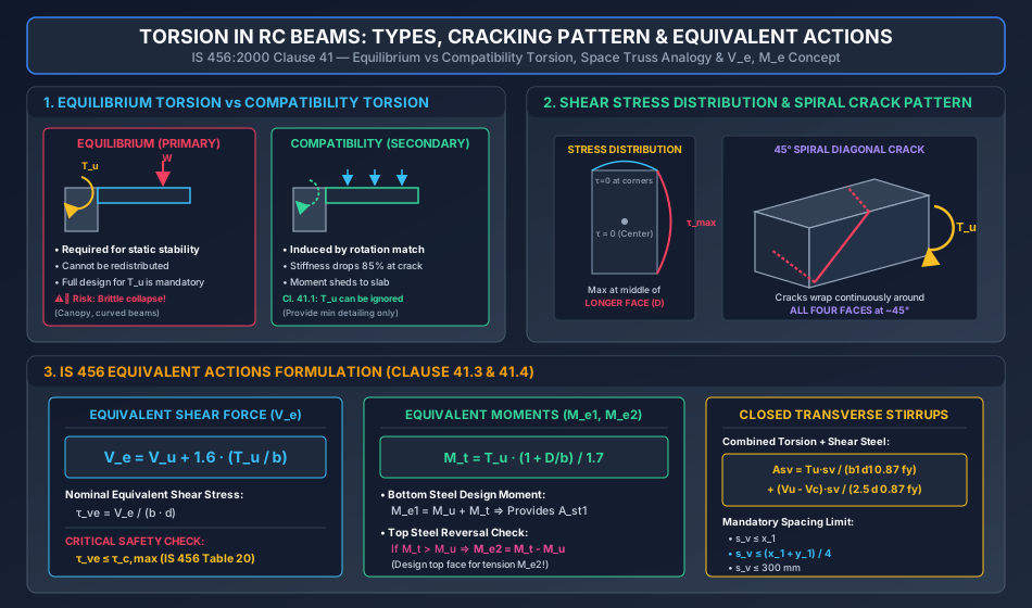
- Equilibrium Torsion (Primary Torsion):
Torsion that is required to maintain static equilibrium in a determinate or indeterminate structure. The torsional moment cannot be reduced or redistributed by structural deformations or cracked hinge formation.
Examples: Cantilever canopies projecting from edge beams, curved beams in plan, ring girders supporting dome shells, inverted L-beams carrying precast slab units.
Design Rule: The member must be fully designed for the calculated factored torsional moment . Omission of torsion design leads to instantaneous collapse. - Compatibility Torsion (Secondary Torsion):
Torsion that arises solely to satisfy the compatibility of angular rotations between adjacent monolithic members in statically indeterminate floor systems. When torsional cracking occurs in an RC beam, its torsional stiffness drops precipitously (by to ), while its flexural stiffness remains largely intact. Consequently, the torsional moment sheds into the adjacent flexural slabs.
Examples: Spandrel edge beams monolithically cast with continuous two-way or one-way floor slabs.
IS 456 Clause 41.1 Provision: When torsional resistance is not relied upon in static equilibrium calculations, the torsional moment may be completely neglected in design, provided nominal minimum shear stirrups and detailing per Clause 26.5.1.7 are provided to control cracking.
2.2 Stress Distribution in Plain Concrete under Torsion (Saint-Venant's Warping)
For non-circular cross-sections (such as rectangles), plane cross-sections do not remain plane under torsion; they warp out of plane.
- Contrary to circular shafts where shear stress is zero at the center and maximum at the outer radius, in a rectangular section of width and depth ():
- The shear stress at the four sharp corners is identically zero ().
- The shear stress at the geometric centroid of the section is zero ().
- The maximum shear stress occurs at the midpoint of the wider vertical faces (): Where is Saint-Venant's torsional coefficient (for ; for ).
- The maximum shear stress at the midpoint of the shorter horizontal faces () is:
2.3 Cracking Pattern & The Space Truss Analogy
Under torsional shear stresses, principal tensile stresses develop along all four faces at an inclination of roughly . When these principal tensile stresses reach the tensile cracking strength of concrete (), spiral diagonal tension cracks form, wrapping continuously around all four faces.
After cracking, the solid concrete core contributes negligibly to torsional resistance. The beam transitions into a thin-walled hollow tube (Space Truss Model):
- Diagonals: The concrete between spiral cracks forms inclined compression struts (typically oriented at ).
- Transverse Ties: Closed transverse stirrups act as tension ties resisting the outward burst and circular shear flow.
- Longitudinal Chords: Longitudinal bars located at the corners act as tension chords resisting the longitudinal component of the inclined diagonal strut forces.
3. IS 456:2000 Design Provisions (Clause 41)
3.1 Equivalent Shear Force ()
Under combined transverse shear and torsion , the shear stress from transverse shear and the shear stress from torsion add directly on one vertical face of the beam. IS 456 Clause 41.3.1 defines an equivalent shear force :
Where:
- = Factored transverse shear force ().
- = Factored torsional moment ().
- = Breadth of the beam web ().
- = Non-dimensional semi-empirical interaction factor derived from space-truss kinematics ().
3.2 Equivalent Nominal Shear Stress ()
The equivalent nominal shear stress is computed as:
Section Adequacy & Crushing Safety Check:
To prevent brittle diagonal compressive crushing of the concrete web struts before reinforcement yields, must satisfy:
Where is obtained from IS 456 Table 20.
Absolute Rule: If , the cross-section must be enlarged (increase and/or ) or concrete grade increased. Adding more stirrup steel will not prevent strut crushing.
4. Equivalent Bending Moments ( and )
Torsional shear stresses circulating around the perimeter produce an equivalent longitudinal bending effect. Per IS 456 Clause 41.4.2, the equivalent torsional moment is:
Where:
- = Overall depth of the beam ().
- = Breadth of the beam web ().
                       LONGITUDINAL STEEL DESIGN MOMENTS
                                       │
            ┌──────────────────────────┴──────────────────────────┐
            ▼                                                     ▼
     CASE 1: M_t ≤ M_u                                     CASE 2: M_t > M_u
  (Normal Flexural Dominated)                          (High Torsion: Moment Reversal)
 ┌─────────────────────────────────┐                 ┌─────────────────────────────────┐
 │ Bottom Steel:                   │                 │ Bottom Steel:                   │
 │   M_e1 = M_u + M_t              │                 │   M_e1 = M_u + M_t              │
 │ Top Steel:                      │                 │ Top Steel (Net Tension!):       │
 │   Provide nominal hanger bars   │                 │   M_e2 = M_t - M_u              │
 │   (no net tension on top)       │                 │   (Must design top bars for     │
 └─────────────────────────────────┘                 │    tensile moment M_e2!)        │
                                                     └─────────────────────────────────┘
4.1 Design of Bottom Tension Reinforcement ()
The longitudinal reinforcement on the flexural tension face (bottom face for simply supported sagging beams) is designed to resist the combined moment:
The area of tensile steel is calculated treating the beam as a standard flexural member subjected to bending moment .
4.2 Moment Reversal and Design of Top Reinforcement ()
On the flexural compression face (top face), the bending compressive stress is countered by the longitudinal tension induced by torsion.
- When : Bending compression dominates. The top face remains in compression. Longitudinal steel on the top face does not require tension design, but at least two corner bars must be provided to anchor the stirrup legs.
- When : The longitudinal tension induced by torsion exceeds the flexural compression. The top face undergoes net tensile stress (moment reversal)!
Per IS 456 Clause 41.4.2.1, the top longitudinal reinforcement must be explicitly designed to resist a reverse bending moment:
The area of top steel is calculated treating the section as a flexural section subjected to moment with tension at the top.
5. Transverse Torsion Reinforcement (Closed Stirrups)
Per IS 456 Clause 41.4.3, transverse reinforcement for combined shear and torsion must be provided in the form of closed stirrups. The required area of stirrups across a spacing is given by:
Where:
- = Cross-sectional area of both legs of a 2-legged closed stirrup ().
- = Longitudinal center-to-center spacing of stirrups ().
- = Center-to-center distance between corner bars along the beam width = ().
- = Center-to-center distance between corner bars along the beam depth = ().
- = Shear capacity of concrete (from IS 456 Table 19).
Note: If , the second term becomes zero (or negative, and is taken as zero). - Rearranging for required stirrup spacing :
6. High-Precision Engineering Diagrams
6.1 Torsion Failure Mechanics, Stress Distributions & Equivalent Actions
The diagram below details equilibrium vs compatibility torsion, Saint-Venant shear stress contours on a rectangular cross-section, 45° spiral cracking wrapping all 4 faces, and IS 456 equivalent shear and moment formulas.
6.2 Torsional Detailing: Closed Cage, Reversal Steel & Side Face Steel
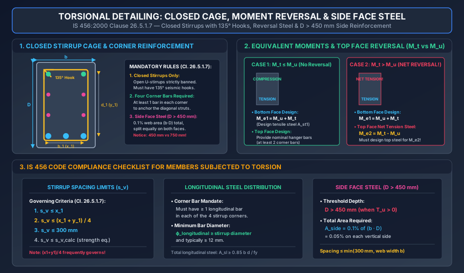
The diagram below details the closed stirrup cage geometry (), 135° seismic hook anchorage, corner bar placement, top face moment reversal (), side face steel trigger (), and governing spacing rules.
7. Detailing and Spacing Rules for Torsion (IS 456 Clause 26.5.1.7)
7.1 Maximum Permissible Stirrup Spacing ()
Transverse stirrups provided for torsion must be spaced closely to ensure that every potential 45° spiral crack intersects at least one stirrup leg on each face. The spacing shall not exceed the least of:
Where:
- = Shorter center-to-center dimension of the closed stirrup ().
- = Longer center-to-center dimension of the closed stirrup ().
- = One-quarter of the stirrup perimeter (this criterion very frequently governs in design!).
7.2 Closed Stirrup Detailing & Corner Bars
- Closed Stirrups Only: Open U-stirrups or stirrups with standard 90° hooks are strictly prohibited. The stirrup must be closed with 135° hooks having an extension of at least (or ) into the concrete core.
- Corner Longitudinal Bars: There must be at least one longitudinal bar in each corner of the closed stirrup. These corner bars serve as the essential tension chords for the space truss.
- Bar Diameter Limit: The diameter of corner longitudinal bars shall not be less than the diameter of the stirrups, and practically not less than .
- Minimum Longitudinal Reinforcement:
7.3 Side Face Reinforcement in Torsion (Clause 26.5.1.7.d)
Because torsional shear stresses are maximum at the mid-depth of the vertical web faces, deep beams subject to torsion are highly prone to lateral web splitting.
- Trigger Depth: When the overall depth of a beam subjected to torsion exceeds (unlike pure flexure where the threshold is !).
- Quantity: Total area of side-face reinforcement of the gross web area ().
- Distribution: Divided equally on the two lateral faces ( per face).
- Maximum Spacing: Spacing of side-face bars along the vertical depth shall not exceed .
8. Pre-Calculated Solved Numerical Examples
Problem 1: Full Design of RC Beam for Combined Torsion, Bending, and Shear (GATE CE / UPSC ESE)
Statement:
A reinforced concrete beam of rectangular section has breadth and overall depth . Effective cover to the center of stirrups is (giving core dimensions and , and effective depth ).
The beam is subjected to:
- Factored bending moment (sagging).
- Factored shear force .
- Factored torsional moment .
The materials are concrete M25 (, ) and steel Fe 415 ().
Perform the design checks for equivalent shear, longitudinal steel, and closed stirrups.
Step 1: Equivalent Shear Force () and Diagonal Crushing Check
Compute equivalent nominal shear stress:
From Table 20, for M25 concrete: .
The section is completely safe against diagonal compression crushing of concrete struts.
Step 2: Equivalent Bending Moments ( and )
Compute torsional moment equivalent :
- Bottom Tension Moment ():
- Top Face Moment Reversal Check (): Since , no moment reversal occurs on the top face. The top face remains in compression under combined loading. Top steel requires only nominal hanger bars (at least 2 corner bars).
Step 3: Design of Bottom Longitudinal Tension Steel ()
Check limiting flexural moment for singly reinforced balanced section:
Since , the section is designed as singly reinforced.
Provide 3 bars of diameter:
Step 4: Concrete Shear Capacity ()
Percentage tensile steel provided:
From Table 19 for M25 concrete:
- At
- At
Since , the term is negative taken as .
Step 5: Design of Closed Transverse Stirrups
Using 2-legged closed stirrups:
Core dimensions: , . From IS 456 Clause 41.4.3:
Check IS 456 Clause 26.5.1.7 Spacing Limits:
- (Governs!)
Therefore, the maximum permissible spacing is .
Final Detailing Specification:
- Bottom Reinforcement: 3 bars of dia ().
- Top Reinforcement: 2 bars of dia (one in each top corner to anchor stirrup legs).
- Side Face Reinforcement: Since , side face steel is required!
per face. Provide 1 bar of dia () on each vertical face at mid-depth. - Transverse Stirrups: 2-legged closed stirrups with 135° hooks @ c/c.
Problem 2: High Torsion with Moment Reversal on Top Face () (UPSC ESE / State AE)
Statement:
A rectangular beam of size and overall depth has effective depth and core dimensions , . It is subjected to factored loads:
- (sagging flexure)
- (large equilibrium torsion)
Concrete is M25 and steel is Fe 415. Design the longitudinal steel on both faces and specify the side-face reinforcement.
Step 1: Equivalent Moments
- Bottom Face Design Moment ():
- Top Face Moment Reversal Check (): Crucial Result: Because , the top face undergoes net tensile stress! The top reinforcement cannot be nominal; it must be designed as tensile reinforcement for moment !
Step 2: Steel Areas Required
- Bottom Tension Steel ( for ): Provide 4 bars of dia ().
- Top Tension Steel ( for ): Using effective depth to top steel : To fulfill the corner bar mandate, provide 2 bars of dia at top corners ().
Step 3: Side Face Reinforcement
Since in a member subjected to torsion:
Area per vertical face .
Provide 2 bars of dia on each vertical face () spaced at c/c ().
Problem 3: Section Sizing to Prevent Concrete Diagonal Crushing (GATE CE)
Statement:
A reinforced concrete edge beam is subjected to a factored shear force and a factored equilibrium torsional moment . The concrete is grade M25 (). For architectural reasons, the aspect ratio of the beam is fixed at , and effective depth .
Determine the minimum web width required to prevent diagonal compressive crushing of the concrete web struts.
Solution:
To prevent diagonal crushing, the equivalent nominal shear stress must not exceed :
Substitute :
Multiply numerator and denominator by :
Solving the cubic equation numerically:
- At
- At
Thus, the minimum required web width is .
In practice, adopt standard beam dimensions: and (or ).
9. Comparative Analysis: Pure Flexure vs Torsion Detailing
| Feature / Detailing Parameter | Pure Flexure & Shear () | Combined Bending, Shear & Torsion () |
|---|---|---|
| Stirrup Shape | Open U-stirrups permitted (with hanger bar ties) | Closed stirrups strictly mandatory with 135° hooks |
| Hook Detail | 90° or 135° standard hooks | 135° seismic hooks with (or ) extension |
| Corner Bar Mandate | Not strictly mandatory in all corners | At least 1 longitudinal bar in all 4 corners |
| Side Face Reinforcement Trigger | Overall depth | Overall depth |
| Side Face Quantity | web area () split equally | web area () split equally |
| Maximum Stirrup Spacing | ||
| Top Face Steel Requirement | Nominal hanger bars ( or ) | Must design for tension if |
| Strut Crushing Criterion |
10. Practical Construction & Site Detailing Guidelines
- Closed Stirrup Tying:
On construction sites, closed stirrups must alternate the positions of their 135° hook laps along the length of the beam (e.g. top-left, top-right, bottom-left, bottom-right). Staggering hook positions prevents creating a continuous longitudinal line of weakness. - Cage Rigidity & Corner Lapping:
Longitudinal bars must be firmly tied to the inside bends of the closed stirrup corners. If corner bars slip out of position, the space-truss node geometry collapses, precipitating premature failure. - Flanged Beams under Torsion:
For T-beams and L-beams monolithic with slabs, IS 456 Clause 41.1 note allows dividing the flanged section into individual rectangular sub-components (web and flange overhangs). Torsion is distributed among the components in proportion to their torsional stiffnesses (). However, conservative site design frequently designs the web alone () to resist 100% of the torsional moment.
11. Common Misconceptions & Exam Traps
[!WARNING]
Ignoring Top Steel Reversal ():
In competitive exams, students often calculate for bottom steel and assume top steel is merely nominal. Whenever , the top face undergoes net tension. Failing to provide steel for will cause immediate cracking and failure under test loads.Confusing Side Face Depth Thresholds:
- For pure flexure/shear: .
- For torsion: .
Examiners frequently specify a beam depth of or with torsion to test if students remember the lower threshold.The Spacing Trap ():
Do not assume applies to torsion. Torsion spacing is limited by . In almost all practical cross-sections, governs.Open U-Stirrup Trap:
Open stirrups have zero torsional capacity because the circular shear flow cannot cross the open top gap. Providing open U-stirrups in an equilibrium torsion beam is a critical design violation.
12. Practice Questions for Self-Assessment
- GATE CE: A rectangular beam of width and overall depth is subjected to a factored shear force and factored torsional moment . What is the equivalent factored shear force ?
(Answer: ) - UPSC ESE: A rectangular beam is subjected to and . Calculate the equivalent torsional moment and determine whether moment reversal occurs on the top face.
(Answer: . Since , no reversal occurs). - SSC JE / State AE: What is the minimum overall depth beyond which side face reinforcement must be provided in an RC beam subjected to torsion?
(Answer: ) - RRB JE: State why closed stirrups with 135° hooks are strictly mandatory for beams subjected to torsion.
(Answer: Torsion creates a continuous circular shear flow around all four faces and diagonal bursting forces that open standard 90° hooks).